Note: Descriptions are shown in the official language in which they were submitted.
CA 02507590 2005-05-27
WO 2004/053269 PCT/US2003/035707
SYSTEM AND RELATED METHODS
FOR SIGNALING THE POSITION OF
A MOVABLE BARRIER AND SECURING ITS POSITION
TECHNICAL FIELD
Generally, the present invention relates to detecting the position of a
movable barrier,
such as a garage door, as it travels between open and closed positions. More
particularly,
the present invention relates to a system which obtains and continually
represents the
positional status of the movable barrier. More specifically, the present
invention relates to
a system which employs a device to detect a position of the movable barrierand
uses either
a visual or audio representation to indicate the position of the barrier. And
the system
includes a feature that blocks wireless signals when it is desired to disable
movement of the
barrier.
BACKGROUND ART
As is well known, motorized garage door operators automatically open and close
a
garage door through a path that is defined by an upper limit and a lower limit
wherein the
limits can be identified electrically or mechanically. The lower limit is
established by the
floor upon which the garage door closes. The upper limit can be defined by the
highest
point the door will travel which can be limited by the operator, a
counterbalance system, or
the door track system's physical limits. The upper and lower limits are
employed to prevent
door damage resulting from the operator's attempt to move a door past its
physical limits.
Under normal operating conditions, the operator's limits may be set to match
the door's
upper and lower physical limits. However, operator limits are normally set to
a point less
than the door's physical upper and lower limits.
Systems used to set operator limits are composed of switches used to terminate
travel
in the up and down directions. These mechanical switches are adjustable and
can be used
by the consumer or an installer to "fit" the door travel to a garage opening.
But these
switches have a liniited life span. Metal fatigue and corrosion are the most
likely causes of
switch failure. Another drawback of inechanical switches is that they can be
wired in series
with the motor which creates high current draw across the contacts of the
switch causing the
contacts to fail. A further liniitation of limit switches is that the up and
down limits, which
must be set manually, can be inlproperly set or misadjusted.
CA 02507590 2005-05-27
WO 2004/053269 PCT/US2003/035707
-2-
Other limit systems employ pulse counters that set the upper and lower travel
of the
door by counting the revolutions of an operator's rotating component. These
pulse counters
are normally coupled to the shaft of the motor and provide a count to a
microprocessor. The
upper and lower limits are programmed into the microprocessor by the consumer
or
installer. As the door cycles, the pulse counter updates the count to the
microprocessor.
Once the proper count is reached, which corresponds to the count of the upper
and lower
limits programmed by the consumer or installer, the door stops. Unfortunately,
pulse
counters cannot accurately keep count. External factors such as power
transients, electrical
motor noise, and radio interference often disrupt the count allowing the door
to over-travel
or under-travel. The microprocessor may also lose count if power to the
operator is lost or
if the consumer manually moves the door while the power is off and the door is
placed in
a new position which does not match the original count.
As described above, there are a number of methods of determining the travel
limits
of a garage door. The main concern, consistently addressed, is to determine
whether the
door is open or is completely closed. One method addresses this with limit
switches placed
at the upper and lower travel limits of the door. These limit switches can be
installed in the
doors path or operated off of a reduced travel jackshaft internal to the
operator housing.
These limit switches can only indicate whether the door is open or not open,
or closed or not
closed. Such a system cannot indicate where the door is, if the door is
neither fully open nor
fully closed. There are also magnetic sensors that can send a signal when in
close proximity
to each other or when the door attracts the magnet due to the door's proximity
to the
magnet. These devices also are limited to the indication of either the door
being closed or
not closed. These types of travel limit devices are sometimes connected to
indicator lights
to give a remote signal as to whether the door is opened or closed and whether
the door is
not opened or not closed, but no indication is provided as to the door's exact
position
between the travel limits.
It is foreseeable to use an encoder or pulse counter that is already
incorporated into
many of these devices to count the rotation of the motor or other rotating
components to
determine the travel distance of the door and therefore the door's position.
But, as noted,
these pulse-counting devices can lose count or need to be reset any time power
is lost. For
example, if a door is closed and power is lost, when the power comes on the
operator does
CA 02507590 2005-05-27
WO 2004/053269 PCT/US2003/035707
-3-
not know if the door is open or closed until the motor is started and the door
either stalls or
begins to move.
T he'systems and methods generally discussed above are disclosed in the
following
patents.
U.S. Patent No. 6,166,634 discloses an improved garage door signaling device
comprising a switch actuable upon opening of the garage door, a transmitter
actuable by said
switch to transmit a signal indicating that the door is open, a receiver
located at a desired
location remote from the garage door providing an audiovisual warning when the
garage
door is not in the closed position, and means for energizing the garage door
signaling
device. However, the audiovisual device provides no specific indication of
door position
as the door moves.
U.S. Patent No. 6,161,438 discloses an internal entrapment system for a door
movable
by a repeatable force that includes a force generating device for transferring
the door
between a first and a second position. A trolley arm connected between the
force generating
device and the door is continually strained during movement of the door. A
sensor mounted
on the trolley arm generates a signal representative of the strain applied to
the trolley arm.
A processor receives the strain signal for comparison to a predetermined
threshold, when
the strain signal exceeds the predetermined threshold, the processor at least
stops the force-
generating device. A potentiometer is coupled to the door for determining a
plurality of
positional locations of the door between the first and the second positions,
wherein the
processor correlates the position of the door with the strain signal for use
in comparison to
the predetermined threshold. A power supply provides electrical power to the
force
generating device, the sensor, the processor, and the potentiometer, and a
decoder/amplifier
circuit, which also receives electrical power from the power supply and
receives the strain
signal for conversion into a format acceptable for use by the processor.
However, no
external output for indicating door position, via the potentiometer, is made.
U.S. Patent No. 6,064,316 teaches an access control system that has at least
one door
associated with a secured area, each door having a strike plate, a host
computer, at least one
door control module coupled to the host computer, one door control module for
every door,
and at least one door reader coupled to the door control module to activate
the strike plate
to release the door. The access control system further has at least one
electro-mechanical
CA 02507590 2005-05-27
WO 2004/053269 PCT/US2003/035707
-4-
key to independently actuate a lock that corresponds to the door(s) and a
master-keying
device to rekey the lock that corresponds to door(s). The host system records
information
selected from the group consisting of time of entry, place of entry,
identification of entered
party, and/or any combination thereof. In addition, a door knob and mechanical
locking
mechanism selectively latches and unlatches the locking mechanism and can be
actuated
with a mechanical key. The system also includes circuitry to actuate the
locking mechanism
to selectively latch so that the door can open, wherein the circuitry is
actuated by an
electrical 'signal transmitted by an electrical key, and wherein the
electrical signal is
communicated by an electrical contact extending through the mechanical locking
mechanism. The circuitry is powered by a battery, which can be removed without
disturbing
or actuating the unlocking mechanism. The contact is an insulated electrical
wire that
extends through the locking mechanism to the circuitry. All of the circuitry
discussed can
be integrated onto a single, monolithic piece of silicon in a multi-chip or
single-chip format.
A master-rekeying device has input/output circuitry to receive and transmit
electrical
signals, and circuitry coupled to the input/output circuitry to record a list
of security
passwords in order to check passwords against the list and a memory to store
data; and the
input/output circuitry also receives and transmits electrical signals to a
host computer.
However, no discussion is provided of a device that blocks an actuation signal
to prevent
door movement.
U.S. Patent No. 5,929,580 discloses an internal entrapment system for a garage
door
operator and includes a motor for transferring a garage door between first and
second
positions. Also included is a pulse counter for detecting a speed of the
garage door during
transfer between first and second positions; a potentiometer for determining a
plurality of
positional locations of the garage door during transfer between first and
second positions
separate from the pulse counter; and a control circuit for calculating a motor
torque value
from the speed for each of the plurality of positional locations to compare
with a plurality
of door profile data points. The control circuit takes corrective action if
the difference
between the motor torque value for each of the plurality of positional
locations and the
plurality of door profile data points exceeds a predetermined threshold. The
control circuit
also updates the plurality of door profile data points to the motor torque
values for each
respective positional location if the predetermined threshold is not exceeded.
In another
CA 02507590 2005-05-27
WO 2004/053269 PCT/US2003/035707
-5-
embodiment both speed and position are detected by a slider element, which is
connected
to the control circuit. In yet another embodiment a sensor detects non-
movement of the door
during an open/close cycle and stops operation of the motor. As with the `438
patent, the
potentiometer provides no external output for indicating door travel position.
U.S. Patent No. 5,689,236 teaches a remote garage doorposition
indicatorcomprising
a magnetic sensor device; a transmitter device being operatively coupled to
the magnetic
sensor device, the transmitter device being capable of transmitting electronic
signals; a
signal interruption device including a plate extending therefrom, in close
orientation to an
outer plate of a receiver device engaging the magnetic sensors of the sensor
device thereby
closing the electrical circuit and causing the transmitter device to cease
sending electronic
signals; and a garage door position indicator including a power source and a
light. The
position indicator includes the receiver means capable of receiving electronic
signals from
the transmitter device. When receiving electronic signals from the
transmitter, the receiver
device causes the light to illuminate. In the closed orientation the
transmitter device does
not emit electronic signals thereby preventing the receiver device from
illuminating the
light. Users can then view the light of the position indicator to determine
whether their
garage door is opened or closed. However, no intermediate positions of the
door are
provided by the indicator.
U.S. PatentNo. 5,402,105 discloses a garage doorposition indicating system
includes
a tilt switch attached to a garage door, an RF transmitter coupled to the tilt
switches, an RF
receiver, and an indicator controlled by the RF receiver. The tilt switch
supplies an enable
signal to the RF transmitter at selected first tilt positions and blocks the
enable signal at
selected second tilt positions. The RF transmitter generates an RF signal in
response to the
enable signal. The RF receiver is responsive to the RF signal and controls an
indicator to
indicate the position of the garage door in either an opened or closed
position, but no
indication is provided for an indication of an in between position.
U.S. Patent No. 4,954,8 10 teaches a signaling system for an automated garage
door
including a transmitter rendered operative upon the opening of the door and a
receiver stage
which may be adhesively mounted on the remote sending unit by which door
operation is
signaled. The receiver stage includes a clock and an audio signal generator
both of which
are disabled by a reset switch. A bar is adhesively affixed to this reset
switch and to the
CA 02507590 2005-05-27
WO 2004/053269 PCT/US2003/035707
-6-
sending unit for common manual articulation of a door closing signal and a
reset signal.
Nothing in this patent discloses that the receiver may receive a blocking
signal to disable
operation of the door.
U.S. Patent No. 4,583,081 teaches a door operator system which includes up and
down limit switches actuated to the closed position when the door reaches the
up and down
travel limits. A processor circuit within the operator is connected to the
limit switches for
ascertaining the position of the door. Bias circuits apply a bias to the
processor when the
limit switches are open. An indicator system comprising a pair of light
emitting diodes
connected across respective limit switches indicates the door position. A
series impedance
element common to both LED circuits prevents actuation of the control circuit
by the light
emitting devices. But, like the other references, no teaching is provided of
an audio or
visual indication of an in between door position.
Based upon the foregoing it is evident that there is a need in the art for a
device that
can indicate the position of a movable barrier anywhere between an open
position and a
closed position. Moreover, there is a need for an indication of the movable
barrier position
by either lights, audible tones or a display to indicate the movable barrier's
position. There
is also a need in the art for the ability to block out signals from
transmitters other than a
main indicator device.
DISCLOSURE OF INVENTION
It is thus an object of the present invention to provide a system for
signaling the
position of a movable barrier comprising a movable barrier; a motor coupled to
the movable
barrier for moving the movable barrier between limit positions; a position
detection device
monitoring the movable barrier to generate a barrier position signal; and an
indication
device to receive the barrier position signal and indicate a position of the
movable barrier
relative to the limit positions.
It is yet another object of the present invention to provide a module for
coupling to
an operator mechanism which controls operation of a motor that moves a movable
barrier
between limit positions, wherein the operator mechanism includes a position
detection
device that generates a barrier position signal and wherein the module
indicates the
CA 02507590 2005-05-27
WO 2004/053269 - PCT/US2003/035707
-7-
positional status of the movable barrier, the module comprising a
communication circuit
capable of exchanging data between the module and the operator mechanism; and
an
indication device that receives the barrier position signal via the
communication circuit and
indicates a position of the movable barrier.
Yet still a further object of the present invention is to provide a method of
remotely
monitoring and controlling the position of a movable barrier comprising
detecting a position
of the movable barrier between travel limit positions and generating a barrier
position
signal; and indicating a representation of the movable barrier's position
based upon the
barrier position signal.
BRIEF DESCRIPTION OF THE DRAWINGS
Fig. 1 is a fragmentary perspective view depicting a frame for a sectional
garage door
and showing an operator mechanism with an intemal entrapment system embodying
the
concepts of the present invention.
Fig. 2 is an enlarged fragmentary schematic view of the operator mechanism of
Fig.
1 as viewed from the inside of the sectional garage door.
Fig. 3 is a schematic view of a control circuit of the operator mechanism used
for
controlling operation of the movable barrier and an indicator module which
communicates
with the operator mechanism.
Fig. 4 is a schematic view of an interface device that is linked with the
indicator
module.
BEST MODE FOR CARRYING OUT THE INVENTION
A system and related methods for signaling the position of a movable barrier
and
securing its position is generally indicated by the numeral 10 in Fig. I of
the drawings. The
system 10 is employed in conjunction with a movable barrier such as a
conventional
sectional garage door generally indicated by the numeral 12. But, the movable
barrier may
also be in the form of a gate, curtain, awning, rollable shutter or the like.
The opening in
which the door is positioned for opening and closing movements relative
thereto is
CA 02507590 2008-10-22
-8-
surrounded by a frame, generally indicated by the numeral 14, which consists
of a pair of
vertically spaced jamb members 16 that, as seen in Fig. 1, are generally
parallel and extend
vertically upwardly from the ground (not shown). The jambs 16 are spaced and
joined at
their vertically upper extremity by a header 18 to thereby form a generally u-
shaped frame
14 around the opening for the door 12. The frame 14 is normally constructed of
lumber or
other structural building materials for the purpose of reinforcement and to
facilitate the
attachment of elements supporting and controlling the door 12.
Secured to the jambs 16 are L-shaped vertical members 20 which have a leg 22
attached to the jambs 16 and a projecting leg 24 which perpendicularly extends
from
respective legs 22. The L-shaped vertical members 20 may also be provided in
other shapes
depending upon the particular frame and garage.door with which it is
associated. Secured
to each projecting leg 24 is a track 26 which extends perpendicularly from
each projecting
leg 24. Each track 26 receives a roller 28 which extends from the top edge of
the garage
door 12. Additional rollers 28 may also be provided on each top vertical edge
of each
section of the garage door to facilitate transfer between opening and closing
positions.
A counterbalancing system generally indicated by the numeral 30 may be
employed
to move the garage door 12 back and forth between opening and closing
positions. One
example of a counterbalancing system is disclosed in U.S. Patent No.
5,419,010.
Generally, the counter-balancing system 30 includes a
housing 32, which is affixed to the header 18 at about a midpoint thereof and
which contains
an operator mechanism generally indicated by the numera134 as seen in Fig. 2.
Extending
from each end of the operator mechanism 34 is a drive shaft 36, the opposite
ends of which
are received by tensioning assemblies 38 that are affixed to respective
projecting legs 24.
The drive shaft 36 provides the necessary mechanical power to transfer the
garage
door 12 between closing and opening positions. The drive shaft 36 provides a
drive gear
42 at about a midpoint thereof wherein the drive gear 42 is coupled to a motor
gear 44.
Driving motion of the motor gear 44 is controlled through a gear box 46 by a
motor 48 in
a manner well known in the art.
A control circuit 50, which is contained within the housing 32, monitors
operation of
the motor 48 and various other elements contained within the operator
mechanism 34 as will
be described hereinbelow. Batteries 52 may be connected to the drive motor 48
for the
CA 02507590 2005-05-27
WO 2004/053269 PCT/US2003/035707
-9-
purpose of energizing the motor 48 and the control circuit 50 to provide any
power required
for the operation thereof. It will be appreciated that the door 12 could be
moved by other
motorized operators such as a trolley type system.
A potentiometer generally indicated by the numera156 is connected to the drive
gear
42 for the purpose of generating a barrier position signal which is used to
determine
positional locations of the door 12. The potentiometer 56 may also be employed
to provide
a speed value for the garage door as it travels between opening and closing
positions. To
this end, a slider 58 extends from the potentiometer 56 and is coupled to the
drive gear 42
to monitor the positional rotation of the drive gear.
A pulse counter 62 is employed to monitor rotation and speed of the motor 48.
The
pulse counter 62 may also generate a barrier position signal and is connected
to the
controller 50 for the purpose of supplying input thereto and allowing the
controller 50 to
take corrective action when required.
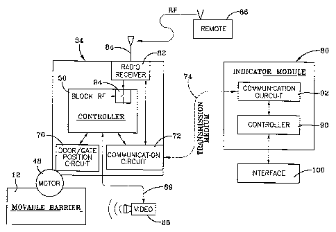
Referring now to Figs. 2 and 3, it can be seen that the control circuit 50
employs a
controller 50 which receives power from the batteries 52 or from an
appropriate power
supply. The controller 50 includes the necessary hardware, software --
including video
processing software -- and memory to implement operation of the controller 50.
The
potentiometer 56 is also connected to the controller 50 wherein it can be seen
that the
potentiometer includes a first end point and a second end point with the
slider 58 disposed
therebetween. In essence, the potentiometer 56 is a variable resistor, wherein
the two end
points have an electrical potential applied across them. If the slider 58 is
moved toward the
end point with the positive potential, then the slider voltage becomes more
positive. If the
slider 58 is moved towards the end point with the negative potential, then the
slider voltage
becomes more negative. By connecting the slider 58 to the door 12 through the
drive gear
42, the potentiometer 56 always outputs a voltage relative to the position of
the door 12.
As noted previously, the potentiometer output voltage can also be used as a
barrier position
signal. If the power supply, for whatever reason, is removed from the control
circuit 50,
the slider 58 still points to a position relative to the door 12. If a user
moves the door while
the operator niechanism 34 is off, the slider 58 maintains a relative position
with respect to_
the door and is reacquired once power is returned to the operator mechanism 34
and the
barrier position signal is re-generated.
CA 02507590 2005-05-27
WO 2004/053269 PCT/US2003/035707
-10-
The operator 34 also includes a position circuit 70 that is connected to the
controller
50. The position circuit 70 receives input from the potentiometer 56 and in
particular, the
voltage output -- the barrier position signal -- which provides an indication
of the door
position with respect to the open and close position limits and a direction of
door travel
between those limits. The position circuit 70 may also receive a barrier
position signal from
the pulse counter 62, although it is believed that the position information
provided by the
potentiometer is more accurate. In any event, the controller 50 includes a
communications
circuit 72 which is connected to the controller 50. The communications circuit
72 receives
signals located away from the operator mechanism and the movable barrier and
allows for
communication with other components that are associated with the overall
system. In
particular; a link 74 is connected between the communications circuit 72 and
an indicator
module 80 to allow for the transfer of data and/or. signals therebetween. It
will be
appreciated that the indicator module 80 is preferably positioned out away
from the operator
mechanism and the movable barrier. In other words, the indicator module 80 is
located in
a position where a user has access to the module 80 but is not in a position
to directly see
the operational status of the movable barrier 12. The advantages of such a
configuration
will be discussed in detail later.
A radio receiver 82 is contained within the controller 50 and has an antenna
84
extending therefrom. The receiver 82 and the antenna 84 allow for receipt of
signals from
a transmitter 86 which may be either a radio frequency device that is portable
or fixed. In
other words, the transmitter may be a device that is contained within an
individual's
automobile or the transmitter may be a device that is associated with a keypad
entry device
or may be a wall station contained within the room or garage associated with
the movable
barrier. Alternatively, the transmitter 86 may be an infrared device as long
as the
communications circuit 72 is configured to receive such a signal. The
transmitter may also
be directly wired to the communications circuit.
As seen in Figs. 1 and 3, a video camera 88 has a view of the movable barrier
and its
various positions. The video camera 88 is mounted in a position to fully view
the movable
barrier and is in such a position as to not be fully obstructed by movement of
automobiles
or the like. The video camera 88 generates a video signal 89 which may also
function as a
barricr position signal. Accordingly, the video cantera 88 functions as a
position detection
CA 02507590 2005-05-27
WO 2004/053269 PCT/US2003/035707
-11-
device similar to the potentiometer and the pulse counter, and may be
considered as a part
of the operator mechanism 34. The video signal 89 is sent to the controller 50
which
contains the necessary video processing software for formatting the video
signal into an
appropriate format for transmission by the communications circuit 72.
The indicator module 80 also functions as a transmitter device that
communicates with
the operator mechanism via the link 74. As will be appreciated, the link 74
may be either
a wired or wireless communication link depending upon the particular placement
of the
indicator module. For example, if the indicator module is contained within a
residential
house it is conceivable that it could be placed in an upstairs bedroom out of
view of the
garage or other enclosure. As such, the module could be a wired device, but it
is quite
conceivable that it could be wireless. In warehouse locations, it is believed
that a wireless
device would be more convenient to set up so as to avoid the need for running
long lengths
of wire. In any event, the indicator module 80 includes an indicator
controller 90 which
includes the necessary hardware, software and memory for communicating with
the operator
mechanism 34. Moreover, the controller 50 includes the necessary video
processing
software for relaying the video signal 89 as will be discussed. A
communications circuit
92 is connected to the indicator controller 90 and is directly connected to
the link 74 for the
purpose of transferring data to the operator controller 50.
The operator mechanism 34 also includes a blocking circuit 94 which is
contained
within controller 50. As will be discussed, the blocking circuit 94 allows for
a user of the
indicator module 80 to block receipt of any other normally appropriate signals
from a
transmitter 86 or similar device. Accordingly, the indicator module 80 in
conjunction with
the circuit 94 may function as a lock to prevent unwanted entry by individuals
at times that
they are not permitted to enter a warehouse, residence or other establishment.
A user interface 100 is coupled to the controller 90 and is best seen in Fig.
4. The
interface device 100 includes an up/down button 102. Actuation of the button
102 generates
a signal that is received by the controller 50 to move the door from an open
position to a
closed position or from a closed position to an open position. Of course, the
operator
mechanisni 34 is associated with the necessary entrapment features to ensure
the safe
operation of the movable barrier. A light button 104 is provided on the user
interface 100
and may be used to control operation of a light 105 extending from the housing
30. The
CA 02507590 2005-05-27
WO 2004/053269 PCT/US2003/035707
=12-
user interface 100 also provides a light on/off indicator light 106 to inform
the user as to
whether the light in the garage is on or off.
The user interface 100 also provides a block button 108 and an associated
on/off
indicator 110. As previously mentioned, the indicator module 100 is preferably
located
remotely from the movable barrier and as such actuation of the block button
108 allows that
user to prevent other users from entering or exiting the garage door without
first re-actuating
the blocking button 108. In other words, actuation of the block button 108
generates a
blocking signal that is transmitted via the controller 90 and the
communications circuit 92
to the blocking circuit 94 carried by the operator mechanism 34. When the
blocking feature
is enabled, any signals received from the transmitter 86 is blocked and the
movable barrier
is prevented from moving.
The user interface 100 also provides a plurality of position indicators or
indication
devices 112. The position indicators 112 are used in conjunction with the
barrier position
signals generated either by the pulse counter 62, the potentiometer 56 or the
video camera
88. Based upon the values generated from the barrier position signals a user
at the user
interface can determine the position of the movable barrier and in what
direction it is
traveling. In particular, one of the position indicators 112 is a "door open"
light 114 that is
illuminated whenever the door is at the fully open limit position. A plurality
of light
emitting or reflecting elements 116 are also provided and these are positioned
between the
"door open" indicator 114 and a "door closed" indicator 118. The indicator 118
is
illuminated whenever the movable barrier is in the fully closed door limit
position. The
elements 116 interposed between the door open and door closed indicators are
provided in
such a configuration that they can be illuminated to represent the door
position.
Accordingly, when a door is fully closed all of the lighting elements 116 are
illuminated.
When the up/down button 102 is actuated the door travels upwardly and the
barrier position
signals change accordingly and the lower most lighting element turns off. As
the door
moves up, the next light would then turn off, and so on. And this change in
light element
status will proceed as the door moves from the closed to the open position.
Conversely, if
the door is in the fully open position the lights will illuminate as the door
travels down
closer to the door closed position. Of course, each of the elements could be
configured to
turn on as the door travels up, and turn off as the door travels down. It is
believed that the
CA 02507590 2005-05-27
WO 2004/053269 PCT/US2003/035707
- 13 -
number of lighting elements could represent the height of the opening that is
closed by the
movable barrier. In other words, each light may represent one foot of door
travel. It is also
believed that more or less lighting elements could be used to convey the same
type of
information. The light elements may be light emitting diodes, a liquid crystal
display or
other similar lighting indicia.
Another type of position indicator 112 is an audible or audio speaker 120. The
audio
speaker 120 could verbally announce the door position on a periodic basis or
whenever the
up/down button is actuated. For example, a user may press the button 102 and
the system
would announce "the door is closing." As the door moves through various
positions the
speaker 120 could announce "ten feet, nine feet, eight feet. :. two feet, one
feet, door
closed." In this way, the user at the user interface 100 would be able to
easily to determine
the door position relative to the open or closed limits. The reverse order
could be
announced as the door moves from the closed position to the open position.
Memory
associated with the controller 90 would store all the needed verbal
announcements.
Yet another position indicator device 112 may be a video display 122 which
allows
for display of the video signal 89. Accordingly, the user could directly
determine the door
position by viewing the video display 122. As part of the video display 122 an
inset
indicator 123 may be provided. This indicator may provide a numerical distance
from the
open position or to the closed position to allow for the user to accurately
determine how far
the movable barrier is from its extreme limits. Moreover, it will be
appreciated that the
controller 50 includes video processing software that may allow for
determination on a
frame-by-frame basis as to the door position relative to its normal fully open
or fully closed
positions. This information could then be used to provide a precise door
position that could
be displayed in the inset 123.
The user interface 100 may also be provided with a stop button 124. Actuation
of the
stop button 124 generates a stop signal that is transmitted to the operator
controller 50 via
the controller 90. Accordingly, as the user receives input from the various
position indicator
devices they can actuate the stop button 124 to place the movable barrier in a
position other
than the fully open or fully closed positions. This allows for a user to vent
the garage or
allow the door to be open a certain amount for pet ingress and egress.
Actuation of the
up/down button 102 would reverse the direction of the door from the stopped
position. It
CA 02507590 2005-05-27
WO 2004/053269 PCT/US2003/035707
-14-
will also be appreciated that actuation of the up/down button 102 during door
travel may
stop movement of the door which will only recommence upon reactuation of the
button 102.
The video display 122 may also include touch screen capabilities. Accordingly,
all
the switcli functions and indicator lights may be part of the touch screen.
For example, the
up/down button 102, the block button 108, the light button 104, and the stop
button 124 may
be positioned on the video display 122. And the indicator or status lights
106, 110, 114, 116
and 118 may be positioned on the display in an ergonomic manner. As such, the
entire
functionality of the user interface 100, except for the speaker 120, may be
provided by the
display 122.
Based upon the foregoing the advantages of the present invention are readily
apparent.
The system allows for an indication of the movable barrier's position at any
point in the
range of the barrier's travel. Accordingly, a user can change the height of
the opening for
pet access and garage venting without visually seeing the door. Initially, the
user interface
allows for the user to immediately know whether the door is in a partially
closed position
as well as the fully opened or fully closed position. The system also allows
for an indication
of the door position if an obstruction is encountered. Moreover, one can
easily determine
which direction the door was traveling when contact was made with the
obstruction. Use
of the blocking device also allows for centralized control of movable barrier
to prevent
unwanted access by individuals who are no longer permitted to enter through
the movable
barrier or to prevent access to individual at inappropriate times.
Thus, it can be seen that the objects of the invention have been satisfied by
the
structure and its method for use presented above. While in accordance with the
Patent
Statutes, only the best mode and preferred embodiment has been presented and
described
in detail, it is to be understood that the invention is not limited thereto or
thereby.
Accordingly, for an appreciation of the true scope and breadth of the
invention, reference
should be made to the following claims.