Note: Descriptions are shown in the official language in which they were submitted.
CA 02508380 2005-05-26
-1 -
RE-ORIENTED OVER FIRE AIR PORTS FOR REDUCTION
OF NOx PRODUCTION FROM PULVERIZED COAL-FIRED BURNERS
Field and Background of the Invention
[001] The present invention relates generally to the field of industrial and
utility
furnaces and boilers and in particular to new and useful over fire air (OFA)
port
configurations for a pulverized coal-fired furnace or boiler which effectively
reduce
NOX production.
[002] NOx is an unintended byproduct from the combustion of fossil fuels, such
as coal. Many industrial furnaces and boilers burn pulverized coal as a
primary fuel.
NOx emissions have been discovered to have a negative effect on the
environment,
and so they are now regulated substantially throughout the world.
[003] Most NOX in furnaces and boilers burning pulverized coal is formed
during
combustion from the fossil fuel. This portion of NOx formation is called fuel
NOx.
Fuel NOx is formed by oxidation of fuel-bound nitrogen during devolatilization
and
char burnout.
[004] An effective method of reducing NOx production which has been known
for many years is to reduce oxygen availability during the critical step of
devolatilization. Oxygen availability can be reduced during devolatilization
by
CA 02508380 2009-01-20
-2-
removing a portion of the combustion air from the burners and introducing the
air
elsewhere in the furnace. This method is commonly referred to as air staging.
[005] Over fire air (OFA) ports are typically used as part of such air staging
systems in furnaces and boilers. The use of such OFA ports is disclosed, for
example, in U.S. Patent Nos. 3,048,131, 5,205,226 and 5,809,913. For a better
understanding of such OFA systems, the reader is referred to Steam/its
generation
and use, 40th Ed., Stultz & Kitto, Eds., Copyright 1992 The Babcock & Wilcox
Company:
[006] The effectiveness of over fire air in NOx suppression depends on the
quantity of over fire air, the point in the burner flame where the over fire
air is
reintroduced, and the rate of reintroduction. Increasing the over fire air
quantity
tends to lower NOx levels from ttie burners, but continual increase of over
fire air
quantity will eventually cause NOx to increase as well. This results from
combustion
being displaced to a region of the furnace or boiler beyond the OFA ports.
[007] The point at which over fire air is introduced into the furnace is
critical as
well, since the purpose of OFA systems is to enable the chemistry to proceed
through a region of lower oxygen concentration in order to suppress NOx
formation
as hydrocarbons preferentially scavenge oxygen. Prematurely adding over fire
air
will negate the benefit as the desired chemistry is disrupted. And, the rate
at which
OFA is added is also important, so as to avoid creating oxygen-rich regions
within
the furnace. It is usual to gradually introduce over fire air to the
combustion process
to complete combustion without locally flooding the flames with oxygen. At the
same
time the OFA ports must be designed with sufficient jet momentum to penetrate
and
supply over fire air throughout the furnace enclosure.
[008] Figs. 1 and 2 illustrate a common prior art arrangement of burners and
OFA ports and the resulting flame paths. The furnace enclosure 10 has three
levels
of burners 12, 14, 16. The enclosure 10 illustrated is typical of opposed-
fired boilers;
that is, burners 12, 14, 16 are oriented through both the front and rear walls
30, 32 of
CA 02508380 2005-05-26
-3-
the enclosure 10, opposite each other. The uppermost level of openings through
each of the front and rear walls 30, 32 of the enclosure 10 is comprised of
OFA ports
20.
[009] In Fig. 2, the approximate flame paths 13, 15, 17 generated by each row
of burners 12, 14, 16 on the front and rear walls 30, 32 are displayed. Bottom
burners 12 fire horizontally, and so flame paths 13 from the opposed burners
12
collide in about the center of the enclosure 10. Unburned combustibles and hot
gases flow upwardly in a path 13a concentrated in the middle of the enclosure
10.
Second level burners 14 are affected by the upward flow 13a of gases and
combustibles, so that second level flame paths 15 from the opposed burners 14
bend upwardly near the middle of the enclosure 10. Third level burners 16 are
even
more affected by the upflow of gases 13a, and so the third level flame paths
17 from
these burners bend upwardly even more quickly than second level flame paths
15.
[0010] As shown, the OFA air path 22 intersects the second and third level
burner flame paths 15, 17 and approaches the upwardly flowing gases and
combustibles 13a. This conventional OFA port configuration of Figs. 1 and 2,
while
useful, provides greatly varying effects when OFA is injected into the
enclosure 10.
The effect on reduction of NOX is not consistent due to differences in
residence time
between the burners and the OFA ports, and differences in gas flow through the
furnace resulting in different interactions of the OFA and flame paths, among
other
factors.
[0011] The OFA configuration illustrated in Figs. 1 and 2, when used in a 600
MW utility boiler or furnace unit for example, will have a calculated bulk
flow
residence time from burners to OFA ports of 2.7 seconds for the bottom burners
12,
1.3 seconds for the second level burners 14 and only 0.6 seconds for the third
level
burners 16. Thus, the level 3 burners 16 suffer from insufficient residence
time
relative to the region of introduction of OFA, which tends to raise the level
of NOx
produced. Often, the most efficient method of reducing NOx emissions in this
type
of furnace is to disable the third level burners 16.
CA 02508380 2005-05-26
-4-
[0012] An alternative for increasing residence time for the second and third
level
burners 14, 16 is to increase the distance between the OFA ports 20 and the
third
level burners 16. However, this also requires additional space in the upper
furnace
region of the enclosure 10. Thus, increasing the OFA port 20 spacing requires
a
taller furnace enclosure 10, thereby increasing the costs and making a bigger
building.
[0013] An OFA configuration which provides consistent minimum residence time
between burner and OFA port but does not require a larger furnace or disabling
existing burners is desirable. Further, an OFA port air flow which is better
managed
for each burner level is also desirable for reducing NOx emissions.
Summary of the Invention
[0014] It is an object of the present invention to provide a novel arrangement
of
OFA ports for further reducing NOx in pulverized coal-fired furnaces and
boilers.
[0015] Another object of the invention is to provide an OFA port configuration
for
improved residence time between the burners and OFA ports.
[0016] Accordingly, a furnace or boiler including the OFA system of the
invention
is provided in which over fire air ports are provided on the furnace enclosure
sidewalls for introducing OFA transverse to the burner flame paths. An OFA
port is
optimally positioned to inject over fire air at each burner level flame path
and provide
good residence time. The air flow rate, air jet velocity and momentum are
adjusted
to produce maximum effectiveness and over fire air penetration into the
furnace
enclosure at the desired burner level flame path while avoiding increasing NOx
production due to excess oxygen being present in higher burner levels.
[0017] A first OFA port arrangement is provided for an opposed-wall fired
furnace
or boiler having three burner levels. One OFA port is positioned to inject air
at
approximately the center of the enclosure where flames from the bottom burners
meet. A pair of OFA ports are provided spaced vertically above and
horizontally
CA 02508380 2005-05-26
-5-
toward the front and rear wall to intersect approximately with the flame path
of the
second level burners. A second pair of OFA ports are provided a further
distance
above the first pair and closer to the front and rear walls for injecting OFA
to
intersect the flame paths of the third level burners.
[0018] An alternate configuration is provided for wide furnace enclosures in
which
some OFA ports are provided in the sidewall and others are located in the
front
and/or rear walls. The OFA ports are positioned through the sidewalls and
spaced
to direct the over fire air to intersect the flame paths from bottom level
burners. OFA
ports for injecting air into the flame path of the upper level burners, such
as the
second and third level burners in a three-high burner level arrangement, are
located
in the front and/or rear walls of the enclosure. Alternately, lower level OFA
ports are
positioned through the sidewalls and spaced to direct over fire air to
intersect the
bottom level burner flame path and upper level OFA ports are also positioned
through the sidewalls to direct over fire air to intersect the second level
burner flame
path. OFA ports for injecting over fire air into the burner flame path of the
third level
burners are located on the front and/or rear walls of the furnace enclosure.
[0019] Another configuration is provided for single-wall fired furnaces and
boilers
in which burners are only positioned through the front wall. OFA ports are
arranged
in the furnace sidewalls in a generally diagonal line extending from the lower
end of
the furnace enclosure adjacent the rear wall toward the upper end of the
enclosure
adjacent the front wall. A number of OFA ports corresponding to or in excess
of the
number of burner levels are provided forming the diagonal line arrangement.
The
OFA ports are positioned to at least inject over fire air across the enclosure
and
generally into the flame path of each burner level.
[0020] The various features of novelty which characterize the invention are
pointed out with particularity in the claims annexed to and forming a part of
this
disclosure. For a better understanding of the invention, its operating
advantages
and specific objects attained by its uses, reference is made to the
accompanying
CA 02508380 2005-05-26
-6-
drawings and descriptive matter in which a preferred embodiment of the
invention is
illustrated.
Brief Description of the Drawings
[0021] In the drawings:
[0022] Fig. 1 is a partial front elevation diagram of burner and OFA ports on
a
prior art furnace enclosure;
[0023] Fig. 2 is a side elevation diagram of the prior art furnace enclosure
of
Fig. 1 illustrating flame paths in the furnace enclosure;
[0024] Fig. 3 is a side elevation diagram of a furnace enclosure having an
over fire air port configuration of the invention;
[0025] Fig. 4 is a side elevation diagram of an alternate embodiment of the
over fire air port configuration of the invention;
[0026] Fig. 5 is a partial perspective view of yet another embodiment of the
over fire air port configuration of the invention;
[0027] Fig. 6 is a partial perspective view of yet another embodiment of the
over fire air port configuration of the invention; and
[0028] Fig. 7 is a side elevation diagram of an embodiment of the over fire
air
port configuration of the invention for a single-wall fired furnace or boiler.
Description of the Preferred Embodiments
[0029] Referring now to the drawings, wherein which like reference numerals
are
used to refer to the same or functionally similar elements throughout the
several
drawings, Figs. 3 - 6 each display a furnace enclosure 10 of an opposed-wall
fired
furnace including an OFA configuration of the invention. Like the enclosure 10
of
Figs. 1 and 2, in each of Figs. 3 - 6, three burner levels 12, 14, 16 are
located in the
front and rear walls 30, 32, respectively. However, as will be appreciated by
those
CA 02508380 2005-05-26
-7-
skilled in the art, the present invention is applicable to single wall fired
and opposed
fired furnace enclosures 10 having fewer or a greater number of burner levels.
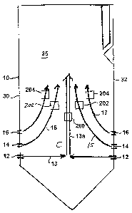
[0030] In Fig. 3, over fire air ports 200, 202, 204 are located in sidewalls
35,
rather than the front or rear walls 30, 32. The OFA ports 200, 202, 204 are
positioned so that the injected air will generally transversely intersect the
burner
flame paths 13a, 15, 17, respectively. That is, bottom OFA port 200 will
inject over
fire air for the flames of the bottom burners 12, middle OFA ports 202 supply
OFA
for second level burners 14, and upper OFA ports 204 inject air for the burner
flame
of third level burners 16.
[0031] The OFA ports 200, 202, 204 are spaced vertically and horizontally, so
that the bottom OFA port 200 is nearest the furnace lower end and center,
while
upper OFA ports 204 are closest to front and rear walls 30, 32 and nearest the
furnace 10 upper end. The OFA ports 200, 202, 204 are arranged to best supply
OFA to the cross-section of the furnace enclosure 10 and burn out combustibles
in
the burner zone. The quantity of over fire air, the air jet velocity and
momentum are
selected to ensure that the over fire air is thrust out into the furnace to
ensure good
mixing of the over fire air supplied via these ports 200, 202 and 204 with the
burner
flame paths 13a, 15 and 17.
[0032] The spacing is designed to deliver OFA to the burner flame paths at a
time
which minimizes NOx production. The vertical and horizontal spacing of the OFA
ports 200, 202, 204 prevents undesirable interaction between the over fire air
and
the flame paths 15, 17 of the second and third level burners 14, 16. The
staggered
arrangement of OFA ports 200, 202, 204 avoids the problem of known OFA systems
in which over fire air is supplied too soon to the flame paths 15, 17 of the
upper level
burners 14, 16. Thus, the transverse OFA supply configuration of the invention
provides more efficient fuel NOx reduction.
[0033] While bottom OFA port 200 is shown elevated above the intersection of
the bottom burner flame paths 13, it may be positioned lower to inject OFA
more
nearly at the intersection. The flames from the bottom burners 12 are expected
to
CA 02508380 2005-05-26
-8-
have proceeded through char reactions shortly after the flame paths 13
intersect.
Thus, introduction of OFA near that point will not adversely cause more fuel
NOx
production.
[0034] The positions of OFA ports 200, 202, 204 may be adjusted to more
accurately direct over fire air into the expected flame paths 13, 13a, 15 or
17. At the
same time, the OFA port positions are set to provide sufficient residence time
between the burners and the over fire air.
[0035] For example, Fig. 4 illustrates an alternate OFA port configuration
with
only two levels of OFA ports 200, 202. The OFA ports 200, 202 are again
staggered
horizontally and vertically. However, the bottom OFA ports 200 are arranged
substantially symmetrically about a vertical centerline (between the front and
rear
walls 30, 32) of the enclosure 10, and therefore, also about the flow of
rising gases
and combustibles represented by the burner flame path 13a. Middle OFA ports
202
are provided above and closer to the front and rear furnace walls 30, 32 than
are the
bottom OFA ports 200.
[0036] The OFA port arrangement of Fig. 5 is best suited for use in furnaces
10
where the cross-sectional ratio of width (W) to depth (D) is approaching or
exceeding 2, however it may be desirable to apply it to furnaces 10 where the
furnace is physically wide (e.g., over 40 feet) regardless of width to depth
ratios.
OFA ports 200, 202 are located through both furnace sidewalls 35 for injecting
over
fire air transversely at the lower level burners 12, 14. In certain
circumstances, only
one OFA port 200 may be employed, substantially at the center of each of the
sidewalls 35. If additional OFA ports 202 are employed, they would be arranged
symmetrically about the OFA port 200, and at a somewhat higher elevation as
shown and described. Additional OFA ports 208 are positioned near the
centerline
of the furnace front and rear walls 30, 32, at an elevation above the
elevation of the
uppermost row of bumers 16. The particular number and placement of these OFA
ports 208 can be determined by computational fluid dynamic (CFD) modeling
techniques known to those skilled in the art. Generally, as the furnace width
W
CA 02508380 2005-05-26
-9-
begins to increase, since penetration of the over fire air into the centermost
portion is
desired, the first OFA ports 208 would be applied at approximately the
centerline of
the front and rear walls, 30, 32, and as furnace width W increased further
(greater
W/D ratios) additional OFA ports 208 would be employed, preferably
substantially
symmetrically on both sides of the centerline of the front and rear walls 30,
32. The
front wall OFA ports 208 better direct OFA air into the center of the furnace
enclosure 10 when the width begins to increase, than transversely oriented OFA
ports alone can. The size of the OFA ports 200, or 208 are selected to ensure
that
an adequate quantity of over fire air, the air jet velocity and momentum are
provided
to ensure that the over fire air is thrust out into the furnace 10 to ensure
good mixing
of the over fire air supplied via these ports with the burner flame paths 13a,
15 and
17.
[0037] In certain circumstances, it may be desirable to place OFA ports 208 so
as
to cover a more substantial portion of the width W of the front and rear walls
30, 32
even where the furnace 10 W/D ratios are at or close to 1, or even less than
1. Fig.
6 illustrates such an application to a furnace configuration where the W/D
ratio is not
much greater than 1, at least one OFA port 200 is employed on each sidewall
35,
and a plurality of OFA ports 208 are employed so as to cover more than just a
central portion of the furnace 10 and along furnace width W. The at least one
OFA
port 200 located on each of the sidewalls 35 is positioned at approximately
the same
elevation as those OFA ports 208 located on the front and rear walls 30, 32.
These
side wall OFA ports 200, in this embodiment, would typically provide
approximately
30% of the over fire air, the balance being provided by the plurality of OFA
ports 208
located in the front and rear walls 30, 32. Under certain circumstances, the
at least
one OFA port 200 on each sidewall 35 may be positioned at approximately the
same
elevation as the elevation of the top row of burners 16, as schematically and
alternately shown in Fig. 6 by 200A, or even at a lower elevation
approximately
corresponding to a center C of the burner zone; i.e. at the elevation of the
middle
row of burners 14 in a three-level burner arrangement, as schematically and
alternately shown in Fig. 6 by 200B.
CA 02508380 2005-05-26
-10-
[0038] Fig. 7 displays an alternate configuration of the OFA ports for use
with a
single-wall fired furnace in which burners 12, 14, 16 are provided only on the
front
wall 30 of the furnace enclosure 10. In this type of furnace, the flame paths
are
initially affected primarily by the presence of the rear wall 32. The flame
paths 13,
15, 17 of the bottom, second and third level burners 12, 14, 16, respectively
are
indicated by the lines as shown.
[0039] OFA ports 200, 202, 204 and 206 are provided through enclosure
sidewalls 35 to inject OFA. OFA ports 200, 202, and 204 are arranged to inject
over
fire air at the flame path of burners 12, 14, 16, respectively. OFA port 206
provides
additional air nearest to the front wall 30 to ensure complete combustion of
the fuel.
[0040] The particular number of OFA ports 200, 202, 204, 206, 208 provided at
any given level can be changed to best deliver OFA to the selected region. For
example, while Fig. 3 illustrates one bottom OFA port 200 and Fig. 4
illustrates two,
three or more could be used if desired to ensure good combustion and coverage.
As noted above, the primary consideration when arranging the OFA ports is to
provide OFA to the correct flame path for a given level, thereby ensuring
suitable
residency time for each burner level.
[0041] The OFA configurations of the invention solve the problem of too rapid
air
introduction to the second and third level burners without requiring a taller
furnace
enclosure. The OFA configurations herein provide a more effective system for
controlling NOx without disabling burner levels. These OFA configurations are
an
inexpensive design which allows tailoring the point of OFA introduction to the
flame
paths to best control NOx for a given type of furnace.
[0042] The OFA configurations of the invention also provide better control of
air
mixing so that flames from the upper level burners are not flooded with air
too soon.
The transverse orientation of the OFA ports in at least the lower levels
permits good
injection of the OFA to the bottom level burner flames without interfering
with the
second and third (or higher) level burner flames. The OFA can be injected in
sufficient quantity from the sidewalls to produce good penetration and
distribution
CA 02508380 2005-05-26
-11 -
into the desired flame path, without detriment to the other burner level flame
paths.
Accordingly, fuel NOx production remains reduced as the second and third level
flames have sufficient time to burn before the introduction of OFA. Thus, air
staging
is made more effective by the transverse orientation of the OFA ports with
respect to
the burner levels. It is believed that the present invention will permit the
percent of
over fire air provided through the sidewalls to be within a range of about 20
to 100%
of the total over fire air. The upper end of this represents a situation where
all the
over fire air is provided via the side wall OFA ports, while the lower end of
the range
represents a situation where over fire air is introduced by both side wall OFA
ports
according to the invention, and front and/or rear wall OFA ports.
[0043] While specific embodiments of the invention have been shown and
described in detail to illustrate the application of the principles of the
invention, those
skilled in the art will appreciate that changes may be made in the form of the
invention covered by the following claims without departing from such
principles.
For example, the present invention may be applied to new construction
involving
industrial or utility steam generators, boilers or furnaces, or to the
replacement,
repair or modification of existing industrial or utility steam generators,
boilers or
furnaces. In some embodiments of the invention, certain features of the
invention
may sometimes be used to advantage without a corresponding use of the other
features. For example, the OFA ports may be employed on the sidewalls alone,
or
in combination with OFA ports on the front, or both of the front and rear
furnace
walls, depending upon the firing arrangement as described herein. Accordingly,
all
such changes and embodiments properly fall within the scope and equivalents of
the
following claims.