Language selection

Search

Patent 2508396 Summary

Third-party information liability

Some of the information on this Web page has been provided by external sources. The Government of Canada is not responsible for the accuracy, reliability or currency of the information supplied by external sources. Users wishing to rely upon this information should consult directly with the source of the information. Content provided by external sources is not subject to official languages, privacy and accessibility requirements.

Claims and Abstract availability

Any discrepancies in the text and image of the Claims and Abstract are due to differing posting times. Text of the Claims and Abstract are posted:

  • At the time the application is open to public inspection;
  • At the time of issue of the patent (grant).
(12) Patent: (11) CA 2508396
(54) English Title: JUICER AND GRATER ASSEMBLY
(54) French Title: PRESSE-FRUITS ET RAPE COMBINES
Status: Granted and Issued
Bibliographic Data
(51) International Patent Classification (IPC):
  • A47J 19/02 (2006.01)
(72) Inventors :
  • DE GROOTE, JAN-HENDRIK (Belgium)
(73) Owners :
  • DART INDUSTRIES INC.
(71) Applicants :
  • DART INDUSTRIES INC. (United States of America)
(74) Agent: GOWLING WLG (CANADA) LLP
(74) Associate agent:
(45) Issued: 2012-04-03
(22) Filed Date: 2005-05-26
(41) Open to Public Inspection: 2005-12-25
Examination requested: 2010-02-18
Availability of licence: N/A
Dedicated to the Public: N/A
(25) Language of filing: English

Patent Cooperation Treaty (PCT): No

(30) Application Priority Data:
Application No. Country/Territory Date
10/875,495 (United States of America) 2004-06-25

Abstracts

English Abstract

The invention provides a juicer and grater assembly comprising an extractor having a plurality of radially extending tabs integral with a lower portion thereof, a combination grater and strainer having at least a plurality of first apertures and a plurality of second apertures, wherein the extractor is removably secured on the combination grater and strainer in either a first position wherein the plurality of radially extending tabs cover the plurality of first apertures for allowing extracted juice to flow through the plurality of second apertures, or in a second position wherein the plurality of radially extending tabs cover the plurality of second apertures allowing juice and pulp to flow through the plurality of first apertures.


French Abstract

Cette invention porte sur un presse-fruits et râpe combinés qui comprend les éléments qui suivent. Un extracteur pourvu de multiples pattes s'étendant radialement et intégrées à la partie inférieure; une râpe et passoire combinées présentant au moins de multiples premières ouvertures et de multiples secondes ouvertures. L'extracteur est fixé de manière amovible sur la râpe et passoire combinées dans une première position où les multiples pattes qui s'étendent radialement recouvrent les multiples premières ouvertures pour que le jus extrait coule à travers les multiples secondes ouvertures. Dans la seconde position, les multiples pattes qui s'étendent radialement recouvrent les multiples secondes ouvertures, ce qui permet au jus et à la pulpe de couler à travers les multiples premières ouvertures.

Claims

Note: Claims are shown in the official language in which they were submitted.

What is claimed is:
1. A juicer and grater assembly, comprising:
an extractor having at least one radially extending tab,
a strainer having at least a first aperture and at least a second aperture,
wherein said extractor is removably secured on said strainer in either a first
position wherein said at least one radially extending tab covers said at least
a first
aperture for allowing extracted juice to flow through said at least a second
aperture, or in a second position wherein said at least radially extending tab
covers said at least a second aperture allowing juice and pulp to flow through
said at least a first aperture.
2. The juicer and grater assembly of claim 1 wherein said at least a first
aperture is a plurality of first apertures.
3. The juicer and grater assembly of claim 1 wherein said at least a
second aperture is a plurality of second apertures.
4. The juicer and grater assembly of claim 1 wherein said extractor
comprises a two-tiered upstanding cone having an upper cone portion and a
lower portion integral with the upper cone portion.
5. The juicer and grater assembly of claim 1 wherein said at least one
8

radially extending tab is a plurality of radially extending tabs in an
alternating
configuration integral with a lower periphery of said second portion.
6. The juicer and grater assembly of claim 4 wherein said extractor
comprises a plurality of longitudinal ridges extending from an apex of the
said
upper cone portion to a lower periphery of said lower portion.
7. The juicer and grater assembly of claim 1 wherein said a least one
radially extending tab includes an indentation at a distal end thereof.
8. The juicer and grater assembly of claim 7 wherein said strainer further
comprises a base having an upper surface and a lower surface, and at least two
protrusions disposed on said upper surface and dimensioned and configured to
engage said indentation on said radially extending tab.
9. The juicer and grater assembly of claim 8 wherein said extractor is
removable snap fit secured to said strainer.
10. The juicer and grater assembly of claim 8 wherein said strainer
comprises a plurality of substantially circular apertures on said flat base
extending from said upper surface to said lower surface.
9

11. The juicer and grater assembly of claim 10 wherein said strainer
comprises a plurality of sharp cutters disposed on said upper surface of said
flat
base and encircling each of said plurality of circular apertures, thereby said
strainer may function as a grater.
12. The juicer and grater assembly of claim 1 wherein said at least a first
aperture is peanut-shaped.
13. The juicer and grater assembly of claim 1 wherein said at least second
aperture is Y-shaped.
14. The juicer and grater assembly of claim 11 wherein said plurality of
first apertures are disposed in an alternating configuration relative to said
plurality
of said second apertures on said upper surface of said flat base.
10

Description

Note: Descriptions are shown in the official language in which they were submitted.


CA 02508396 2005-05-26
JUICER AND GRATER ASSEMBLY
TECHNICAL FIELD
The present invention is directed toward a manually operated juicer, and
more particularly, toward a juicer and grater assembly.
BACKGROUND OF THE INVENTION
Prior art manual juicers are commonly used to extract juice from cut citrus
fruit. One problem associated with the prior art manual juicers is that they
collect
pulp and seed on a strainer around the juicer and allow only the juice to pass
through to the reservoir below. Therefore, if juice with pulp is desired, a
separate
step or apparatus is required to collect juice with pulp.
Moreover, since graters are not commonly used everyday, if a user
desires to grate or zest the outer layer or skin of the citrus fruit, he must
use a
separate grater, which requires purchase and storing an additional kitchen
appliance.
It is therefore a primary object of the present invention to provide a manual
juicer and grater assembly that will provide for both juice and juice with
pulp when
desired, and a grater for grating the outer layer or skin of citrus fruit.
SUMMARY OF THE INVENTION
These problems and others are addressed by the present invention
1

CA 02508396 2005-05-26
which comprises a juicer and grater assembly having an extractor having a
plurality of radially extending tabs integral with a lower portion thereof, a
combination grater and strainer having at least a plurality of first apertures
and a
plurality of second apertures, wherein the extractor is removably secured on
the
combination grater and strainer in either a first position wherein the
plurality of
radially extending tabs cover the plurality of first apertures for allowing
extracted
juice to flow through the plurality of second apertures, or in a second
position
wherein the plurality of radially extending tabs cover the plurality of second
apertures allowing juice and pulp to flow through the plurality of first
apertures.
BRIEF DESCRIPTION OF DRAWINGS
These and other objects of the present invention will be appreciated and
understood by those skilled in the art from the detailed description of the
preferred embodiments of the invention and the following drawings of which:
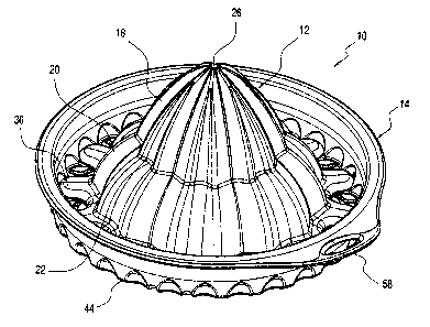
Figure 1 is a top perspective view of the juicer and grater assembly
according the present invention;
Figure 2 is a bottom perspective view of the juicer and grater assembly
according to Figure 1;
Figure 3 is an exploded perspective view of the juicer and grater
assembly;
Figure 4 is a top plan view of the juicer and grater assembly of Figure 1 in
a juice only position;
2

CA 02508396 2005-05-26
Figure 5 is a top plan view of the juicer and grater assembly of Figure 1 in
a juice and pulp position; and,
Figure 6 is a side sectional view of the juicer and grater assembly and
taken along line 6-6 of Figure 4.
DETAILED DESCRIPTION OF THE INVENTION
Referring now to the drawings, and more specifically Figure 1, wherein the
showings are for the purpose of illustrating the preferred embodiment of the
invention only and not for the purpose of limiting the same, a juicer and
grater
assembly 10 is shown in an assembled configuration that includes an extractor
12 and a combination grater and strainer 14, wherein the extractor 12 is
removably secured on the combination grater and strainer 14 in a locked
position
which prevents the rotation of the extractor 12 relative to the combination
grater
and strainer 14. Preferably, the extractor 12 and the combination grater and
strainer 14 are molded of plastic material. It should be appreciated that the
juicer
and grater assembly 10 may be used with any juice reservoir or container (not
shown) by placing the assembly on top of the juice reservoir opening.
Referring now to Figure 3, the extractor 12 and the combination grater and
strainer 14 are shown separated from each other. The extractor 12 includes a
two-tiered upstanding cone 16 comprising an upper cone portion 18 integral
with
a lower portion 20 along a circumferential line 22. As will be explained in
greater
detail herein, the upper cone portion 18 can be used to extract juice from
smaller
3

CA 02508396 2005-05-26
citrus fruit such as lemon, and the lower portion 20 can be used to extract
juice
from larger citrus fruit such as orange. The two-tiered upstanding cone 16
further
includes a plurality of longitudinal ridges 24 extending from an apex 26 to a
lower
periphery 28 of the lower portion 20.
A plurality of radially extending tabs 30 are preferably integrally formed
and extend outwardly from the lower periphery 28 of the lower portion 20. As
best seen in Figure 6, each radially extending tab 30 includes a proximal end
34
attached to the lower periphery 28 and a distal end 36 having a step or an
indentation 38, which, as will be explained in greater detail, provides for a
snap fit
securing of the extractor 12 to the combination grater and juicer 14.
Referring now to Figures 2 and 3, the combination grater and strainer 14
includes a substantially circular and flat base 40 bounded by an annular wall
42
integrally formed and extending upwardly from a peripheral edge 44 of the flat
base 40. The flat base 40 further includes an upper surface 46 and a lower
surface 48 wherein a plurality of substantially circular openings 50 are
disposed
thereon and extend from the upper surface 46 to the lower surface 48. The
plurality of substantially circular openings 50 are preferably arrange in a
concentric circular configuration of increasing diameter from the center of
the flat
base 40. A plurality of sharp cutters or perforations 52 are disposed on the
upper
surface 46 of the flat base 40 and around the perimeter of the each of the
substantially circular openings 50, wherein the sharp cutters 52 allow for
grating
of the outer layer or skin of citrus fruit. The combination grater and
strainer 14
4

CA 02508396 2005-05-26
may function as a grater or zester when it is not assembled with the extractor
12.
An annular flange 54 extends outwardly from the upper periphery 32 of the
annular wall 42, and a grip portion tab 58 is integral with and extends beyond
the
annular flange 54. The combination grater and strainer further comprises a
first
protrusion 56 and a second protrusion 57 disposed on the upper surtace 46 of
the flat base 40 and adjacent the lower peripheral edge 44 of the annular wall
42.
The first and second protrusions are dimensioned and configured to removable
engage the indentation 38 of the extractor 12 thereby, as will be explained in
greater detail, snap fit secure the extractor 12 with the combination grater
and
strainer 14.
Moreover, the combination grater and strainer 14 includes a first plurality
of substantially peanut-shaped apertures 60 disposed on and around the
perimeter of the flat base 40 and adjacent the peripheral edge 44, in
alternating
configuration relative to a second plurality of substantially Y-shaped
apertures 64
also disposed on the flat base 40 and adjacent the peripheral edge 44. It
should
be appreciated that the plurality of peanut-shaped apertures 60 and the
plurality
of Y-shaped apertures 64 may have other shapes and configurations without
departing form the spirit of the invention, which is to provide two sets of
varying
sized apertures. As will be explained herein, each peanut-shaped aperture 60
has a larger dimension than that of the Y-shaped aperture, therefore allowing
for
the passage of pulp and juice therethrough, wherein each Y-shaped aperture is
dimensioned to prevent the passage of pulp therethrough.

CA 02508396 2005-05-26
The extractor 12 and the combination juicer and grater 14 are assembled
in two positions: a first juice position, as best seen in Figure 4, and a
second juice
and pulp position, as best seen in Figure 5. To assemble the juicer and grater
assembly 10 in the first juice position, the extractor 12 is placed on the
upper
surface 46 of the circular flat base 40 and slightly pressed down so that the
indentation 38 of one of the plurality of radial tabs 30 engages the first
protrusion
56, which is disposed at the periphery of one of the peanut-shaped apertures
60.
The remaining radial tabs 30 also cover a corresponding peanut-shaped aperture
60, and because the plurality of radial tabs 30 are formed along the lower
periphery 28 of the lower portion 20 in an alternating configuration, the Y-
shaped
apertures 64 become exposed and allow the extracted juice to flow to the
reservoir below and holding the pulp on the upper surface 46 of the base 40.
Similarly, to assemble the juicer and grater assembly 10 in the second juice
and
pulp position, the extractor 12 is placed on the upper surface 46 of the flat
base
40 and slightly pressed down so that the indentation 38 of one of the
plurality of
radial tabs 30 engages the second protrusion 57, which is disposed at the
periphery of one of the Y-shaped apertures 64. The remaining radial tabs 30
cover a corresponding Y-shaped aperture 60, and because the plurality of
radial
tabs 30 are integrally formed with the lower periphery 28 of the lower portion
in
an alternating configuration, the peanut-shaped apertures 60 become exposed
and allow the extracted juice together with pulp to flow to the reservoir
below.
While preferred embodiments of the invention have been shown and
6

CA 02508396 2005-05-26
described, various modifications and substitutions may be made thereto without
departing from the spirit and scope of the invention. Accordingly, it is to be
understood that the present invention has been described by way of
illustration
only, and this description should not be construed as limiting to the several
claims
appended hereto.
7

Representative Drawing
A single figure which represents the drawing illustrating the invention.
Administrative Status

2024-08-01:As part of the Next Generation Patents (NGP) transition, the Canadian Patents Database (CPD) now contains a more detailed Event History, which replicates the Event Log of our new back-office solution.

Please note that "Inactive:" events refers to events no longer in use in our new back-office solution.

For a clearer understanding of the status of the application/patent presented on this page, the site Disclaimer , as well as the definitions for Patent , Event History , Maintenance Fee  and Payment History  should be consulted.

Event History

Description Date
Inactive: COVID 19 - Deadline extended 2020-05-14
Common Representative Appointed 2019-10-30
Change of Address or Method of Correspondence Request Received 2018-01-10
Grant by Issuance 2012-04-03
Inactive: Cover page published 2012-04-02
Pre-grant 2012-01-23
Inactive: Final fee received 2012-01-23
Notice of Allowance is Issued 2011-12-06
Letter Sent 2011-12-06
Notice of Allowance is Issued 2011-12-06
Inactive: Approved for allowance (AFA) 2011-12-02
Letter Sent 2010-03-12
Request for Examination Requirements Determined Compliant 2010-02-18
All Requirements for Examination Determined Compliant 2010-02-18
Request for Examination Received 2010-02-18
Application Published (Open to Public Inspection) 2005-12-25
Inactive: Cover page published 2005-12-25
Inactive: First IPC assigned 2005-08-04
Inactive: Filing certificate - No RFE (English) 2005-07-07
Filing Requirements Determined Compliant 2005-07-07
Letter Sent 2005-07-07
Application Received - Regular National 2005-07-06

Abandonment History

There is no abandonment history.

Maintenance Fee

The last payment was received on 2011-05-06

Note : If the full payment has not been received on or before the date indicated, a further fee may be required which may be one of the following

  • the reinstatement fee;
  • the late payment fee; or
  • additional fee to reverse deemed expiry.

Patent fees are adjusted on the 1st of January every year. The amounts above are the current amounts if received by December 31 of the current year.
Please refer to the CIPO Patent Fees web page to see all current fee amounts.

Owners on Record

Note: Records showing the ownership history in alphabetical order.

Current Owners on Record
DART INDUSTRIES INC.
Past Owners on Record
JAN-HENDRIK DE GROOTE
Past Owners that do not appear in the "Owners on Record" listing will appear in other documentation within the application.
Documents

To view selected files, please enter reCAPTCHA code :


To view images, click a link in the Document Description column. To download the documents, select one or more checkboxes in the first column and then click the "Download Selected in PDF format (Zip Archive)" or the "Download Selected as Single PDF" button.

List of published and non-published patent-specific documents on the CPD .

If you have any difficulty accessing content, you can call the Client Service Centre at 1-866-997-1936 or send them an e-mail at CIPO Client Service Centre.


Document
Description 
Date
(yyyy-mm-dd) 
Number of pages   Size of Image (KB) 
Drawings 2005-05-25 4 238
Abstract 2005-05-25 1 20
Description 2005-05-25 7 233
Claims 2005-05-25 3 75
Representative drawing 2005-11-29 1 26
Courtesy - Certificate of registration (related document(s)) 2005-07-06 1 114
Filing Certificate (English) 2005-07-06 1 158
Reminder of maintenance fee due 2007-01-28 1 111
Reminder - Request for Examination 2010-01-26 1 118
Acknowledgement of Request for Examination 2010-03-11 1 177
Commissioner's Notice - Application Found Allowable 2011-12-05 1 163
Correspondence 2012-01-22 2 49