Note: Descriptions are shown in the official language in which they were submitted.
CA 02508869 2005-06-08
WO 2004/054311 PCT/US2003/039497
1
DISCONTINUOUS TRANSMISSION (DTX) DETECTION IN WIRELESS
COMMUNICATION SYSTEMS
BACKGROUND
Field
[1001] The present invention relates generally to communication, and more
specifically to
techniques for detecting discontinuous transmission (DTX) frames in wireless
communication
systems.
Background
[1002] Wireless communication systems are widely deployed to provide various
types of
communication. These systems may be multiple-access systems capable of
supporting
communication with multiple users by sharing the available system resources.
Examples of
such multiple-access systems include code division multiple access (CDMA)
systems, time
division multiple access (TDMA) systems, and frequency division multiple
access (FDMA)
systems. A CDMA system may be designed to implement one or more standards such
as IS-
2000, W-CDMA, IS-856, IS-95, and so on.
[1003] Many newer generation wireless communication systems, such as IS-2000
and W-
CDMA systems, support flexible operation. For example, data may be transmitted
at any one
of a number of supported rates on the forward and reverse channels. Moreover,
a forward
channel may be operated in a non-continuous manner whereby data frames may not
be
transmitted some or most of the time. This non-continuous transmission is also
referred to as
discontinuous transmission (DTX). For IS-2000 and W-CDMA systems, no data
frames are
actually transmitted on the forward channel during periods of no transmission,
and these non-
transmitted frames are often referred to as DTX frames.
[1004] For certain functions, it is necessary to accurately detect what type
of frame was
received in each frame interval. For example, in an IS-2000 system, a base
station is allowed
to discontinue its transmission on a Forward Dedicated Control Channel (F-
DCCH) when it
has no data to send to a terminal (e.g., a cellular phone). The F-DCCH may be
configured to
carry a Forward Power Control Subchannel, which includes power control (PC)
bits for the
terminal. The PC bits are transmitted on the F-DCCH even during periods of no
data
transmission. If the Forward Power Control Subchannel is carried on the F-
DCCH, then the
terminal would need to determine whether a good, bad (erased), or DTX frame
was received
CA 02508869 2005-06-08
WO 2004/054311 PCT/US2003/039497
2
in each frame interval. This information is needed to properly control the
transmit power of
the F-DCCH, so that the PC bits for the Forward Power Control Subchannel can
be correctly
detected by the terminal even during periods of no data transmission.
[1005] The determination of whether or not a received frame is a good frame is
typically
trivial, and may be made based on a cyclic redundancy check (CRC) value
included in each
transmitted data frame. However, the determination of whether the received
frame is erased
or DTX (if the CRC fails) is more challenging. This is because a failed CRC
can result from a
data frame being transmitted but received in error (i.e., an erased frame), or
no data frame
being transmitted (i.e., a DTX frame). Some other metrics besides the CRC
would then be
needed to detect for DTX frames.
[1006] There is therefore a need in the art for techniques to accurately
detect DTX frames
on a forward channel in wireless (e.g., IS-2000 and W-CDMA) communication
systems.
SUMMARY
[1007] Techniques are provided herein to detect for DTX frames in a "primary"
transmission that may be sent in a non-continuous manner. A "secondary"
transmission that
is sent even during periods of no transmission for the primary transmission is
used to detect
for DTX frames in the primary transmission. For an IS-2000 system, the primary
transmission may be the data transmission on the Forward Fundamental Channel
(F-FCH) or
the F-DCCH, and the secondary transmission may be the PC bit transmission on
the Forward
Power Control Subchannel that is carried on the F-FCH or F-DCCH.
[1008] In an embodiment, a method is provided for detecting DTX frames in a
wireless
(e.g., IS-2000 or W-CDMA) communication system. In accordance with the method,
a
determination is first made whether or not a frame received for the primary
transmission in a
particular frame interval is a good frame (e.g., based on a CRC value included
in each
transmitted frame). If the received frame is not a good frame, then a
determination is next
made whether the received frame is a DTX frame or an erased frame based on a
number of
metrics determined for the primary and secondary transmissions received during
the particular
frame interval.
[1009] The metrics may include (1) the symbol error rate (SER) of re-encoded
symbols
for the received frame, (2) the energy of the secondary transmission received
during the
particular frame interval (e.g., PC bit energy), and (3) the energy of the
received frame for the
primary transmission. For simplicity, a combined metric may be computed based
on all three
CA 02508869 2005-06-08
WO 2004/054311 PCT/US2003/039497
3
metrics (i.e., the SER, PC bit energy, and frame energy) and used to determine
the received
frame type (i.e., erased or DTX).
[1010] Various aspects and embodiments of the invention are described in
further detail
below.
BRIEF DESCRIPTION OF THE DRAWINGS
[1011] The features, nature, and advantages of the present invention will
become more
apparent from the detailed description set forth below when taken in
conjunction with the
drawings in which like reference characters identify correspondingly
throughout and wherein:
[1012] FIG. 1 illustrates a wireless communication system;
[1013] FIG. 2 illustrates the F-FCH, F-DCCH, and Forward Power Control
Subchannel
defined by IS-2000;
[1014] FIG. 3 illustrates the detection of received frames at a terminal;
[1015] FIG. 4 shows probability density functions (PDFs) of SERB for erased
and DTX
frames;
[1016] FIG. 5 shows distributions of erased and DTX frames when plotted by SER
versus
normalized PC bit energy;
[1017] FIG. 6 is a flow diagram of a process for detecting DTX frames for a
non-
continuous transmission on a forward channel; and
[1018] FIG. 7 is a block diagram of a base station and a terminal in the
wireless
communication system.
DETAILED DESCRIPTION
[1019] FIG. 1 is a diagram of a wireless communication system 100. System 100
includes a number of base stations 104 that communicate with a number of
terminals 106. A
base station is a fixed station used for communicating with the terminals and
may also be
referred to as a base transceiver system (BTS), a Node B, an access point, or
some other
terminology. A terminal may also be referred to as a mobile station, a remote
station, an
access terminal, a user equipment (UE), or some other terminology. Each
terminal may
communicate with one or multiple base stations on the forward link and/or
reverse link at any
given moment. This depends on whether or not the terminal is active, whether
or not soft
handoff is supported for data transmission, and whether or not the terminal is
in soft handoff.
CA 02508869 2005-06-08
WO 2004/054311 PCT/US2003/039497
4
[1020] A system controller 102 couples to base stations 104 and may further
couple to a
public switched telephone network (PSTN) and/or a packet data network (PDN).
System
controller 102 may also be referred to as a base station controller (BSC), a
mobile switching
center (MSC), a radio network controller (RNC), or some other terminology.
System
controller 102 provides coordination and control for the base stations coupled
to it. Via the
base stations, system controller 102 further controls the routing of calls (1)
among the
terminals, and (2) between the terminals and other users and entities coupled
to the PSTN
(e.g., conventional telephones) and PDN.
[1021] The techniques described herein for detecting DTX frames may be
implemented in
various wireless communication systems. Thus, system 100 may be a CDMA system,
a
TDMA system, or some other type of system. A CDMA system may be designed to
implement one or more standards such as IS-2000, IS-X56, W-CDMA, IS-95, and so
on. A
TDMA system may be designed to implement one or more standards such as Global
System
for Mobile Communications (GSM). These standards are well known in the art and
incorporated herein by reference. For clarity, the DTX frame detection
techniques are
described specifically for a cdma2000 system that implements IS-2000.
[1022] On the forward link, the capacity of each base station is limited by
its total transmit
power, subject to the availability of physical channel resources. Each base
station may
transmit data to a number of terminals concurrently on the same frequency
band. A portion of
the base station's total transmit power is then allocated to each active
terminal such that the
aggregate power allocated to all terminals is less than or equal to the total
transmit power. To
maximize forward link capacity while providing the desired level of
performance for each
active terminal, the transmit power for each user-specific transmission from
the base station
may be controlled to be as low as possible.
[1023] On the reverse link, a base station may receive signals transmitted
from a number
of terminals. The received signal from each terminal acts as interference to
the received
signals from all other terminals. To maximize reverse link capacity, the
transmit power of
each active terminal may also be controlled to be as low as possible.
[1024] A forward link power control loop is typically used to adjust the
transmit power
for the user-specific transmission sent to each terminal such that the
received signal quality at
the terminal is maintained at a particular target signal-to-noise-and-
interference ratio (SNR),
which is often referred to as the setpoint. A reverse link power control loop
is also typically
used to adjust the transmit power of each terminal such that the received
signal quality at the
CA 02508869 2005-06-08
WO 2004/054311 PCT/US2003/039497
base station is maintained at another setpoint, which may or may not be the
same as the
setpoint used for the forward link. The forward and reverse link power control
loops are
operated independently. Each power control loop requires a feedback stream
from the
receiver (typically in the form of power control (PC) bits or PC comm nds),
which is used by
the transmitter to adjust its transmit power for the transmission sent to the
receiver.
[1025] In an IS-2000 system, a terminal may be assigned an F-FCH and/or an F-
DCCH
for data transmission on the forward link. The F-FCH is used to send data to
the terminal.
The F-DCCH is typically used to send control data for the F-FCH. The F-FCH or
F-DCCH
may also be configured to carry the Forward Power Control Subchannel.
[1026] FIG. 2 is a diagram illustrating the F-FCH, F-DCCH, and Forward Power
Control
Subchannel defined by IS-2000. The transmission timeline for the F-FCH and F-
DCCH is
partitioned into (20 msec) frame intervals. Each frame interval is further
partitioned into 16
(1.25 msec) power control groups (PCGs), which are numbered from 0 through 15.
Data may
be transmitted in 5 msec or 20 msec frames on the F-FCH and F-DCCH.
[1027] The Forward Power Control Subchannel may be transmitted on either the F-
FCH
or F-DCCH, which is dictated by the base station. The Forward Power Control
Subchannel
includes one PC bit for the reverse link power control loop (i.e., one FL PC
bit) for each
power control group. Each FL PC bit occupies 1112-th of a power control group
and is
pseudo-randomly located within the power control group. The remaining portion
of each
power control group is used to transmit data for the F-FCH or F-DCCH. The FL
PC bits are
used to adjust the transmit power of the terminal.
[1028] If the F-FCH is configured to carry the Forward Power Control
Subchannel, then
each data frame transmitted on the F-FCH is detected and used to adjust the
setpoint that
controls the transmit power of the F-FCH and F-DCCH. Each data frame
transmitted on the
F-FCH includes a CRC value, and this CRC value can be used by the terminal to
determine
the status of the received frame. If the CRC passes, then the received frame
is classified as a
good frame (i.e., transmitted by the base station and received by the terminal
without errors).
Alternatively, if the CRC fails, then the received frame is classified as bad
or erased (i.e.,
transmitted by the base station and received by the terminal with errors). The
received frame
status (e.g., good or erased) may be used by the forward link power control
loop to control the
transmit power of the F-FCH and F-DCCH.
[1029] The F-DCCH may be operated in a non-continuous manner. If the F-DCCH is
configured to carry the Forward Power Control Subchannel, then FL PC bits are
transmitted
CA 02508869 2005-06-08
WO 2004/054311 PCT/US2003/039497
6
on the forward link even during periods of no data transmission on the F-DCCH.
The
transmit ,power for the forward link would still need to be properly
controlled during periods
of no data transmission so that the FL PC bits can be correctly detected by
the terminal. This
requires accurate determination of whether a good, erased, or DTX frame was
received by the
terminal for each frame interval.
[1030] Techniques are described herein to accurately detect for DTX frames
when the
forward channels) being monitored (e.g., the F-DCCH) is operated in a non-
continuous
manner. The CRC value included in each transmitted data frame may be used to
determine
whether or not a received frame is good. However, the CRC cannot be used to
determine
whether a received frame is an erased frame or a DTX frame. Other metrics
(described
below) are used instead to make this determination. The techniques described
herein can
provide accurate detection of DTX frames (i.e., with low probability of false
detection), which
is highly desirable. False detection results from declaring a received frame
as being an erased
frame when it is actually a DTX frame, or declaring the received frame as
being a DTX frame
when it is actually an erased frame.
[1031] FIG. 3 is a diagram illustrating the detection of received frames at a
terminal.
FIG. 3 also shows the generation of reverse link (RL) PC commands based on the
detected
frames. The RL PC commands are used to adjust the transmit power of the
forward link
transmission to the terminal.
[1032] The base station generates and transmits a forward link signal to the
terminal. This
forward link signal includes user-specific traffic and control data (if
available) and FL PC bits,
overhead data and signaling, and so on, all of which are carried on their
designated forward
channels/subchannels. For a cdma2000 system, the user-specific traffic and
control data may
be transmitted in (5 or 20 msec) data frames on the F-FCH andlor F-DCCH, a
pilot is
transmitted on a Forward Pilot Channel (F-PICH), and the FL PC bits are
transmitted on the
Forward Power Control Subchannel. Since the pilot is intended to be received
by all
terminals in the coverage area of the base station, the transmit power for the
F-PICH is
typically fixed at a particular power level. However, the traffic and control
data on the F-FCH
and F-DCCH are user-specific, and the transmit power for these forward
channels can be
individually adjusted for each terminal (block 312).
[1033] The forward link signal is transmitted over a wireless channel (cloud
314) to the
terminal. Due to path loss in the wireless channel, which typically varies
over time and
CA 02508869 2005-06-08
WO 2004/054311 PCT/US2003/039497
7
especially for a mobile terminal, the quality of the signal received by the
terminal continually
fluctuates.
[1034] At the terminal, the received signal is processed by a signal quality
measurement
unit 322 to determine the energy of each received frame and the energy of the
FL PC bits for
each frame interval. The frame energy may be computed in various manners and
may take
into account symbol errors in the received frame, as described below. Unit 322
provides the
PC bit energy and frame energy to a DTX frame detector 324.
[1035] A receive processor 332 also processes the received signal to detect
and recover
each frame received on the F-FCH and F-DCCH. Receive processor 332 demodulates
data
samples (which are derived by digitizing the received signal) to obtain
recovered symbols,
decodes the recovered symbols for each received frame to obtain decoded bits,
and further
checks each decoded frame based on its CRC value to determine the status of
the frame (i.e.,
good or not good). For DTX frame detection, receive processor 332 also re-
encodes the
decoded bits for each received frame to obtain re-encoded code symbols,
compares the re-
encoded symbols against the recovered symbols, and determines symbol errors
and a symbol
error rate (SER) for the received frame. Receive processor 332 provides the
frame status (i.e.,
good or not good) and the SER for each received frame to DTX frame detector
324. Receive
processor 332 may also provide indications of symbol errors to signal quality
measurement
unit 322, which may use this information in determining the frame energy.
[1036] DTX frame detector 324 receives various metrics including the PC bit
energy and
frame energy from unit 322 and the frame status and SER from receive processor
332. DTX
frame detector 324 then determines whether each received frame is good,
erased, or DTX
based on these metrics. The detection for DTX frames is described in detail
below. DTX
frame detector 324 then provides a frame indicator (i.e., good, erased, or
DTX) for each
received frame to a setpoint adjustment unit 326, which updates the setpoint
based on the
frame indicator and provides the current setpoint to a PC command generator
328.
[1037] PC command generator 328 receives the setpoint from setpoint adjustment
unit
326 and possibly other metrics (e.g., the received signal quality from unit
322). Generator
328 then derives PC commands for the reverse link power control loop. These RL
PC
commands are sent back to the base station on a Reverse Power Control
Subchannel and used
to adjust the transmit power for the F-FCH and F-DCCH. This ensures that the
FL PC bits
can be correctly detected by the terminal even when there is no data
transmission on the F-
DCCH.
CA 02508869 2005-06-08
WO 2004/054311 PCT/US2003/039497
8
[1038] The detection of DTX frames may be performed based on various metrics.
One
such metric is the SER. An example conventional DTX detection algorithm that
uses only the
CRC and SER may be expressed in pseudo-code, as follows:
if CRC =- 'pass'
Frame indicator = 'Good"
else if SER > SER threshold
Frame indicator = 'DTX'
else
Frame indicator = 'Erasure'
[1039] FIG. 4 shows probability density functions (PDFs) of the SERs for
erased frames
and DTX frames. The left vertical axis represents probability of occurrence,
and the
horizontal axis represents SERB. The probability of obtaining any given SER
for erased
frames is given by a plot 410, which is the PDF of the SERs for erased frames.
Similarly, the
probability of obtaining any given SER for DTX frames is given by a plot 412,
which is the
PDF of the SERs for DTX frames.
[1040] The SER threshold used to detect DTX frames may be represented by a
vertical
line 414 at a particular SER value. For the above algorithm, a received frame
would be
detected as a DTX frame if the SER for the frame is greater than the SER
threshold, and
detected as an erased frame otherwise (assuming that the CRC fails).
[1041] As shown in FIG. 4, the PDFs for the erased and DTX frames overlap.
Thus,
regardless of which SER value is used for the SER threshold, there will be
detection error.
The probability of detection error (or false detection) from erasure-to-DTX is
given by shaded
area 420, which is to the right of line 414 and under plot 410. The
probability of detection
error from DTX-to-erasure is given by area 422, which is to the left of line
414 and under plot
412. A tradeoff can be made between the erasure-to-DTX probability and the DTX-
to-erasure
probability by adjusting the SER threshold. However, as may be visualized from
the plots in
FIG. 4, if the erasure-to-DTX probability is to be kept under 10 percent, then
the DTX-to-
erasure probability may be quite high (e.g., up to 50 percent under certain
operating
scenarios).
[1042] In an embodiment, the detection of DTX frames is performed based on
three
metrics - SER, PC bit energy, and frame energy. As described above for FIG. 4,
SER alone is
insufficient to provide accurate detection of DTX frames. However, if a
secondary
transmission is available for the DTX frames, such as the FL PC bits on the F-
FCH or F-
CA 02508869 2005-06-08
WO 2004/054311 PCT/US2003/039497
9
DCCH, then the energy of this secondary transmission may be used along with
the SER to
more accurately detect for DTX frames. The PC bit energy is normalized by
dividing it by the
frame energy.
[1043] FIG. 5 shows the distributions of erased and DTX frames when plotted by
SER
versus "normalized" PC bit energy. The normalized PC bit energy is equal to
the PC bit
energy divided by the frame energy. The horizontal axis represents SERs, and
the vertical
axis represents normalized PC bit energies.
[1044] The SERs and normalized PC bit energies are determined for a number of
erased
frames and, when plotted, result in a distribution 510. Similarly, the SERs
and normalized PC
bit energies are determined for a number of DTX frames and, when plotted,
result in a
distribution 512.
[1045] As shown in FIG. 5, the distribution of erased frames, when plotted
using these
metrics, overlaps very little with the distribution of DTX frames. The energy
of a DTX frame
tends to be smaller for a given transmit power level for the F-FCH and F-DCCH,
which then
results in larger normalized PC bit energy for the DTX frame. Conversely, the
energy of an
erased frame tends to be larger for the same transmit power level for the F-
FCH and F-DCCH,
which then results in smaller normalized PC bit energy for the erased frame.
Thus, the
distributions for the erased and DTX frames are separated from each other when
plotted using
these metrics.
[1046] A threshold line 514 may be defined for use to determine whether a
given received
frame is an erased or DTX frame. An erased frame is declared if the SER and
normalized PC
bit energy for the received frame map to a point that is below threshold line
514, and a DTX
frame is declared otherwise.
[1047] The erased and DTX frame distributions shown in FIG. 5 are for a
specific
operating scenario, which is defined by the following parameters : Radio
Configuration (RC)
3 in IS-2000, additive white Gaussian noise (AWGN) channel, 2-path (i.e., two
propagation
paths for the transmitted signal), power control ON, 1 percent frame error
rate (FER), and
geometry (G) = 3 dB . Different operating scenarios may be associated with
different sets of
erased and DTX frame distributions.
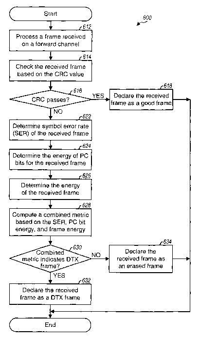
[1048] FIG. 6 is a flow diagram of an embodiment of a process 600 for
detecting DTX
frames for a non-continuous transmission on a forward channel. For this flow
diagram, it is
assumed that the forward channel is the F-DCCH, which is configured to carry
the Forward
CA 02508869 2005-06-08
WO 2004/054311 PCT/US2003/039497
Power Control Subchannel. Process 600 is performed for each received frame to
determine its
type (i.e., good, erased, or DTX).
[1049] For each frame interval, the F-DCCH is processed to attempt to recover
a data
frame that may have been transmitted in the frame interval (step 612). The F-
DCCH
processing typically includes demodulation and decoding, and may be performed
in a manner
known in the art. The result of step 612 is a sequence of decoded bits for the
received frame.
The received frame is then checked based on a CRC value for the frame (step
614).
[1050] A determination is then made whether or not the CRC passes (step 616).
If the
answer is yes, then the received frame is declared as a good frame (step 618),
and the process
terminates.
[1051] Otherwise, if the CRC fails in step 616, then the SER of the received
frame is
determined (step 622). This may be achieved by re-encoding the decoded bits
and comparing
the re-encoded symbols against the recovered symbols. Since the re-encoded
symbols are
binary values and the recovered symbols are typically soft decisions (i.e.,
multi-bit values),
the symbol error detection may be performed by comparing each re-encoded
symbol with the
polarity of the corresponding recovered symbol to determine whether or not
there is a symbol
error. The SER is then equal to the number of symbol errors divided by the
total number of
recovered symbols for the received frame. Since a division is normally
difficult to perform,
the SER may be given by the total number of symbol errors in the received
frame for a given
frame size.
[1052] The FL PC bits received for the frame interval are also processed, and
the energy
of these PC bits is determined (step 624). The PC bit energy may be computed
by (1)
summing the squares of the inphase (I) and quadrature (Q) components for each
PC bit, and
(2) accumulating the summed values for the 16 PC bits in the frame interval.
[1053] The energy of the received frame is also determined (step 626). The
frame energy
may be computed in various manners. In one embodiment, the frame energy is
computed by
(1) determining the energy of each recovered symbol in the received frame as
the sum of the
squares of the I and Q components for the recovered symbol, and (2)
accumulating the
energies of all recovered symbols (i.e., except for the PC bits). In a second
embodiment, the
frame energy is computed by (1) determining the energy of each recovered
symbol in the
received frame, (2) accumulating the energies of all good recovered symbols
(i.e., those with
the same polarity as their corresponding re-encoded symbols), (3) accumulating
the energies
of all bad recovered symbols (i.e., those with opposite polarity as their
corresponding re-
CA 02508869 2005-06-08
WO 2004/054311 PCT/US2003/039497
11
encoded symbols, which are symbol errors), and (4) subtracting the bad
recovered symbol
energy from the good recovered symbol energy to obtain the frame energy. The
frame energy
determined in this manner is also referred to as the "decoded frame energy".
(The frame
energy used for FIG. 5 is determined using the second embodiment.) In general,
the PC bit
energy and frame energy may be computed using various techniques, including
those
described in the U.S. Patent Nos. 5,056,109 and 5,265,119. Steps 622, 624, and
626 may be
performed (e.g., by units 322 and 332 in FIG. 3) for a received frame only if
the CRC fails.
[1054] The determination of whether the received frame is erased or DTX is
then made
based on the SER, PC bit energy, and frame energy. This may be achieved
visually by
plotting the SER and normalized PC bit energy (i.e., PC bit energy/frame
energy) for the
received frame (e.g., as shown in FIG. 5) and determining whether or not the
plotted point
falls above or below the threshold line (e.g., line 514 in FIG. 5).
[1055] However, for simplicity, a combined metric is computed based on the
SER, PC bit
energy, and frame energy (step 628), as follows:
Combined metric = SER - Slope ~ PC Bit Energy + ~tercept , Eq (1)
Frame Energy
where Slope is the slope of the threshold line used to demarcate (or separate)
the erased
frames from the DTX frames, and Intercept is the SER value for the threshold
line with the
normalized PC bit energy set equal to zero (0.0). The slope is equal to
USER / Normalized PC Bit Energy .
[1056] For threshold line 514 in FIG. 5, equation (1) may be expressed as:
Combined metric = SER - 520 ~ PC Bit Energy
+ 380 , Eq (2)
Frame Energy
where the Slope is equal to 520 and the Intercept is equal to -380 (e.g., SER
is equal to 140
when the normalized PC bit energy is equal to 1.0).
[1057] The values for Slope and Intercept are dependent on the specific
threshold line
used to demarcate the erased frames from the DTX frames, which may in turn be
dependent
on the distributions of erased and DTX frames using the defined metrics. As
noted above,
different distributions may be obtained for different operating scenarios, in
which case
different threshold lines with different sets of Slope and Intercept values
may be used for
different operating scenarios. The Slope and Intercept values may be
determined statically at
CA 02508869 2005-06-08
WO 2004/054311 PCT/US2003/039497
12
the start of operation or they may be dynamically determined and assigned
(e.g., at a specified
update rate). The Slope and Intercept values may be dynamically determined
based on
various factors such as current estimates of the SER, frame energy, PC bit
energy, CRC, and
so on. The dynamic assignment of the Slope and Intercept values may provide
improved
performance under dynamically changing channel conditions.
[1058] The threshold line may also be defined based on a higher-order function
or a non-
linear function instead of a linear function as shown in equations (1) and
(2). For example,
the threshold line may be defined based on a quadratic function.
[1059] A determination is then made whether or not the combined metric
indicates a DTX
frame (step 630). This would be the case if the combined metric computed based
on equation
(1) or (2) is less than 0. As an example, if the SER is equal to 220 and the
normalized PC bit
energy is equal to 2.0, then the combined metric computed by equation (2)
would be -440 and
would indicate a DTX frame. As another example, if the SER is equal to 180 and
the
normalized PC bit energy is equal to 0.8, then the combined metric from
equation (2) would
be 144 and would indicate an erased frame. If the answer for step 630 is yes,
then the
received frame is declared as a DTX frame (step 632). Otherwise, the received
frame is
declared as an erased frame (step 634). In either case, the process then
terminates.
[1060] The detection of DTX frames based on SER, PC bit energy, and frame
energy may
be expressed in pseudo-code, as follows:
if CRC =- 'pass'
Frame indicator = 'Good"
else if SER c 520*PC Bit Energy/Frame Energy - 380
Frame indicator = 'DTX'
else
Frame indicator = 'Erasure'
Again, other values may be used for the slope and intercept for other
operating scenarios.
[1061] The innovative DTX detection algorithm, which uses SER, PC bit energy,
and
frame energy, was simulated for various operating scenarios. The simulation
shows that this
DTX detection algorithm can provide superior performance over the conventional
algorithm
that uses only SER. In particular, the innovative DTX detection algorithm can
provide DTX-
to-erasure false detection probability on the order of 1 percent for most
cases, and erasure-to-
DTX false detection probability also on the order of 1 percent.
CA 02508869 2005-06-08
WO 2004/054311 PCT/US2003/039497
13
[1062] FIG. 7 is a block diagram of an embodiment of a base station 104x and a
terminal
106x. On the forward link, a transmit (TX) data processor 710 receives data of
various types
and processes (e.g., formats, encodes, and interleaves) the received data. The
processed data
is provided to a modulator (MOD) 712 and further processed (e.g., channelized
with one or
more channelization codes, spectrally spread with a pseudo-random noise (PN)
sequence, and
so on). The modulated data is then provided to a transmitter unit (TMTR) 714
and
conditioned (e.g., converted to one or more analog signals, amplified,
filtered, frequency
upconverted, and so on) to generate a forward link signal. The forward link
signal is routed
through a duplexer (D) 716 and transmitted via an antenna 718 to the
terminals.
[1063] Although not shown in FIG. 7 for simplicity, base station 104x is
capable of
processing and transmitting data and signaling on one or more forward
channels/subchannels
(e.g., the F-FCH, F-DCCH, Forward Power Control Subchannel, and so on) to a
particular
terminal. The processing (e.g., encoding and modulation) for each forward
channel/subchannel may be different from that of other forward
channels/subchannels.
[1064] At terminal 106x, the forward link signal is received by an antenna
752, routed
through a duplexer 754, and provided to a receiver unit (RCVR) 756. Receiver
unit 756
conditions (e.g., filters, amplifies, and frequency downconverts) the received
signal and
further digitizes the conditioned signal to provide data samples. A
demodulator (Demod) 758
further processes (e.g., despreads, channelizes, and data demodulates) the
data samples to
provide recovered symbols (i.e., demodulated data). Demodulator 758 may
implement a rake
receiver that can process multiple signal instances in the received signal.
[1065] A decoder 760 then deinterleaves and decodes the recovered symbols to
provide
decoded bits, and further checks each received frame to determine the status
of the frame.
The frame status indicates whether or not a good frame was received for each
frame interval
and is provided to a DTX frame detector 774. An encoder/comparator 762 re-
encodes the
decoded bits for each received frame to obtain re-encoded symbols, and
compares the re-
encoded symbols against the recovered symbols to determine symbol errors (SE)
and the SER
of each frame. The SER is provided to DTX frame detector 774, and the
indication of symbol
errors may be provided to unit 772 and used to determine the frame energy.
[1066] For the detection of DTX frames, the data samples from receiver unit
756 are also
provided to a signal quality measurement unit 772, which determines the energy
of the PC bits
received on the Forward Power Control Subchannel and the energy of each
received frame.
The frame energy may be computed in a manner that takes into account good and
bad
CA 02508869 2005-06-08
WO 2004/054311 PCT/US2003/039497
14
recovered symbols (i.e., symbol errors), as described above. The PC bit and
frame energies
are provided to DTX frame detector 774.
[1067] For each received frame that is not a good frame, DTX frame detector
774
determines whether the frame is an erased frame or a DTX frame based on the
SER, PC bit
energy, and frame energy, as described above. DTX frame detector 774 can
implement the
process shown in FIG. 6 to detect for DTX frames. DTX frame detector 774
provides the
frame indicator (good, erased, or DTX) for each received frame to controller
780, which may
then generate RL PC commands used to adjust the transmit power of the forward
channel.
[1068] On the reverse link, a TX data processor 790 receives and processes
(e.g., formats,
encodes) various types of data. A modulator 792 receives and further processes
(e.g.,
channelizes and spectrally spreads) the data from TX data processor 790. For
IS-2000, the RL
PC commands may be multiplexed with pilot data and transmitted on the Reverse
Pilot
Channel. The modulated data is then conditioned by a transmitter unit 794 to
generate a
reverse link signal, which is then routed through duplexer 754 and transmitted
via antenna 752
to one or more base stations.
[1069] At base station 104x, the reverse link signal is received by antenna
718, routed
through duplexer 716, and provided to a receiver unit 738. Receiver unit 738
conditions the
received signal, digitizes the conditioned signal, and provides a sample
stream to each channel
processor 740. Each channel processor 740 includes a demodulator 742 and an RX
signaling
processor 744 that receive and process the sample stream for one terminal to
recover the
transmitted data and RL PC commands. A power control processor 720 receives
the RL PC
commands and adjusts the transmit power of the forward channel for the
terminal (including
the Forward Power Control Subchannel used to send FL PC bits) based on these
RL PC
commands. Power control processor 720 is also provided with the received
signal quality for
the reverse link signal from the terminal, and determines FL PC bits to be
sent on the Forward
Power Control Subchannel to the terminal.
[1070] Controllers 730 and 780 direct the operation of various processing
units within the
base station and terminal, respectively. Controller 780 may also be designed
to perform
various functions for DTX frame detection such as, for example, determining
the PC bit
energy and frame energy, computing the combined metric, determining whether
the received
frame is erased or DTX, and so on. Thus, controller 780 may be designed to
implement unit
772 and/or detector 774. Memory units 732 and 782 may store data and program
codes used
by various processing units within the base station and terminal,
respectively.
CA 02508869 2005-06-08
WO 2004/054311 PCT/US2003/039497
[1071] For clarity, various aspects and embodiments of the DTX frame detection
have
been specifically described for a cdma2000 system that implements IS-2000. In
general, these
techniques may be used to detect for DTX frames in a primary transmission that
may be
transmitted in a non-continuous manner. A secondary transmission that is
transmitted during
periods of no transmission for the primary transmission is then used to detect
for DTX frames
in the primary transmission. For a cdma2000 system, the primary transmission
may be the
one sent on the F-FCH or F-DCCH, and the secondary transmission may be the one
sent on
the Forward Power Control Subchannel. The secondary transmission rnay be any
transmission having transmit power that is related to that of the primary
transmission.
[1072] The detection of DTX frames may also be performed based on other
combinations
of metrics beside the specific combination described above which includes the
SER, PC bit
energy, and frame energy. For example, the DTX detection may be performed
based on a
combination of just SER and frame energy, a combination of SER and PC bit
energy, and so
on.
[1073] The techniques described herein may be used to detect for DTX frames on
the
reverse link as well as the forward link. These techniques may also be used
for various
wireless communication systems, such as IS-2000 and W-CDMA systems.
[1074] The DTX frame detection techniques described herein may be implemented
by
various means. For example, these techniques may be implemented in hardware,
software, or
a combination thereof. For a hardware implementation, the DTX frame detection
may be
implemented within one or more application specific integrated circuits
(ASICs), digital
signal processors (DSPs), digital signal processing devices (DSPDs),
programmable logic
devices (PLDs), field programmable gate arrays (FPGAs), processors,
controllers, micro-
controllers, microprocessors, other electronic units designed to perform the
functions
described herein, or a combination thereof.
[1075] For a software implementation, the DTX frame detection may be
implemented
with modules (e.g., procedures, functions, and so on) that perform the
functions described
herein. The software codes may be stored in a memory unit (e.g., memory unit
782 in FIG. 7)
and executed by a processor (e.g., controller 780). The memory unit may be
implemented
within the processor or external to the processor, in which case it can be
communicatively
coupled to the processor via various means as is known in the art.
[1076] The previous description of the disclosed embodiments is provided to
enable any
person skilled in the art to make or use the present invention. Various
modifications to these
CA 02508869 2005-06-08
WO 2004/054311 PCT/US2003/039497
16
embodiments will be readily apparent to those skilled in the art, and the
generic principles
defined herein may be applied to other embodiments without departing from the
spirit or
scope of the invention. Thus, the present invention is not intended to be
limited to the
embodiments shown herein but is to be accorded the widest scope consistent
with the
principles and novel features disclosed herein.
[1077] WHAT IS CLAIMED IS: