Note: Descriptions are shown in the official language in which they were submitted.
CA 02508971 2005-06-O1
SHIFT CONTROL APPARATUS FOR CONTINUOUSLY VARIABLE
TRANSMISSION
FIELD OF THE INVENTION
The present invention relates to a shift control apparatus for a
continuously variable transmission. More specifically, the present
invention relates to a shift control apparatus for a continuously variable
transmission including a shift actuator that changes a gear ratio regardless
of an engine speed.
BACKGROUND OF THE INVENTION
An electric vehicle powered by a motor offers advantages of no air
pollution, smaller noise pollution, and better response to acceleration and
deceleration needs as compared with conventional vehicles powered by
engines. A hybrid vehicle mounted with a motor and an engine has been
put into practical use as an embodiment taking these benefits.
Three types of such a hybrid vehicle are generally known: a "series hybrid
system," a "parallel hybrid system," and a "series-parallel combined
system." Specifically, the series hybrid system is powered only by the
motor, with the engine being used for generating electricity for recharging
a battery. The parallel hybrid system uses both the motor and the engine
for driving the vehicle, each being used according to a running condition
and the like. The series-parallel combined system uses the foregoing two
systems, one being selected for use appropriately according to the running
condition.
In many of such a hybrid vehicle, a belt-type continuously variable
transmission is adopted as an automatic transmission. The belt-type
continuously variable transmission includes a driving side pulley, a
driven side pulley, and an endless belt. The driving side pulley is
connected to an output shaft of a power source. The driven side pulley is
connected to a driving shaft. The endless belt is wound around the
driving side pulley and the driven side pulley. The gear ratio is changed
by displacing a radius of the driving side pulley using a centrifugal force
generated by rotation of the output shaft.
WH-12664/cs
CA 02508971 2005-06-O1
-2-
Japanese Patent Laid-open No. 2004-116672 discloses an electronic
controlled belt-type continuously variable transmission as against the
conventional belt-type continuously variable transmission. What is called
an electronic belt converter, the electronic controlled belt-type
continuously variable transmission includes a separate shift actuator that
displaces the radius of the driving side pulley. The electronic belt
converter is capable of arbitrarily controlling its gear ratio regardless of
the
speed of the output shaft.
FIG. 9 is a diagram showing a typical shift pattern of a conventional
electronic belt converter. A relation among an engine speed Ne, a vehicle
speed V, and a gear ratio R of the continuously variable transmission has
been previously registered. The shift pattern includes a low ratio control
range, a top ratio control range, and a shift control range. In the low ratio
control range, the engine speed Ne is variably controlled at a low speed
range with the gear ratio R set at a predetermined low ratio Rlow. In the
top ratio control range, the engine speed Ne is variably controlled at a high
speed range with the gear ratio R set at a predetermined top ratio Rtop. In
the shift control range, the gear ratio is variably controlled with the engine
speed Ne fixed at a boundary between the low speed range and the high
speed range.
There is known a system, in which power of an engine is used to drive a
generator for generating electricity which, in turn, is used to charge a
battery. In such a system, the more a charging current as a result of an
amount of charge still available for use in the battery, or a remaining
charge of the battery, the greater a driving torque for the generator. This
results in an engine mechanical load increasing. To obtain, when the
remaining charge of the battery is low, running performance equivalent to
that with a sufficient remaining charge of the battery, therefore, a rider
needs to open even more largely a throttle grip. This gives the rider an
impression different from that during ordinary operation.
The present invention has been made in view of the problems in the prior
art described above. It is therefore an object of the present invention to
provide a shift control apparatus for a continuously variable transmission
WH 12664/cs
CA 02508971 2005-06-O1
-3-
ensuring an operating feel similar to that during ordinary running
regardless of the remaining charge of the battery.
SUMMARY OF THE INVENTION
To achieve the foregoing object, the present invention is characterized in
that the following measures are taken in a shift control apparatus for a
continuously variable transmission including: a continuously variable
transmission for transmitting power of an engine to a driving wheel; a
shift actuator for changing a gear ratio of the continuously variable
transmission; and gear ratio control means for controlling the shift
actuator such that the gear ratio of the continuously variable transmission
exhibits a predetermined shift pattern.
The present invention is characterized in that the shift control apparatus
for the continuously variable transmission further includes battery
monitoring means for detecting remaining charge of a battery charged by a
generator connected to the engine, and the shift pattern is changed
according to the remaining charge of the battery.
In a second aspect of the invention the shift control apparatus for the
continuously variable transmission is characterized in that the shift
pattern changes such that the more the battery lacks in the remaining
charge, the lower the gear ratio.
In a third aspect of the invention the shift control apparatus for the
continuously variable transmission is characterized in that the shift
pattern includes: a low ratio control range, in which an engine speed is
variably controlled at a low speed range with the gear ratio set at a
predetermined low ratio; a top ratio control range, in which the engine
speed is variably controlled at a high speed range with the gear ratio set at
a predetermined top ratio; and a shift control range, in which the gear
ratio is variably controlled with the engine speed fixed at a boundary
between the low speed range and the high speed range; and that the lower
the remaining charge of the battery, the more the low ratio control range is
expanded to the high speed range of the engine.
WH 12664/cs
CA 02508971 2005-06-O1
-4-
In a fourth aspect of the invention the shift control apparatus for the
continuously variable transmission is characterized in that the shift
pattern includes: a low ratio control range, in which an engine speed is
variably controlled at a low speed range with the gear ratio set at a
predetermined low ratio; a top ratio control range, in which the engine
speed is variably controlled at a high speed range with the gear ratio set at
a predetermined top ratio; and a shift control range, in which the gear
ratio is variably controlled with the engine speed fixed at a boundary
between the low speed range and the high speed range; and that the lower
the remaining charge of the battery, the more the gear ratio of the low
ratio control range is shifted to a low ratio side.
In a fifth aspect of the invention the shift control apparatus ' for the
continuously variable transmission is characterized in that the shift
pattern includes: a low ratio control range, in which an engine speed is
variably controlled at a low speed range with the gear ratio set at a
predetermined low ratio; a top ratio control range, in which the engine
speed is variably controlled at a high speed range with the gear ratio set at
a predetermined top ratio; and a shift control range, in which the gear
ratio is variably controlled with the engine speed fixed at a boundary
between the low speed range and the high speed range; and that the lower
the remaining charge of the battery, the more the gear ratio of the low
ratio control range is shifted to a low ratio side, and the more the low ratio
control range is expanded to the high speed range of the engine.
In a sixth aspect of the invention the shift control apparatus for the
continuously variable transmission is characterized in that the
continuously variable transmission is a belt type continuously variable
transmission having an endless belt wound around a driving side pulley
and a driven side pulley; and that the shift actuator changes a belt winding
diameter of at least either the driving side pulley or the driven side pulley.
In a seventh aspect of the invention the shift control apparatus for the
continuously variable transmission is characterized in that the shift
pattern does not change during running.
According to the present invention, the following effects are achieved.
WH 12664/cs
CA 02508971 2005-06-O1
-5-
According to the first aspect of the present invention, the shift pattern of
the automatic transmission is changed according to the remaining charge
of the battery. If the gear ratio is shifted, when the remaining charge of the
battery is insufficient, to a lower ratio side than when the remaining
charge of the battery is sufficient, insufficient torque of the engine is
supplemented with the gear ratio even if a driving torque of the generator
increases as a result of an insufficient remaining charge of the battery and
a mechanical load on the engine becomes greater. This gives the rider the
same operating feel as that during ordinary running.
According to the second aspect of the present invention, the lower the
remaining charge of the battery, the lower the gear ratio is selected.
Insufficient torque of the engine is supplemented with the gear ratio even
if a driving torque of the generator increases as a result of an insufficient
remaining charge of the battery and a mechanical load on the engine
becomes greater. This gives the rider the same operating feel as that
during ordinary running.
According to the third aspect of the present invention, the lower the
remaining charge of the battery, the more the low ratio control range is
expanded to the high speed range of the engine. As a result, the gear ratio
in the shift control range is shifted on a low end. This gives the rider the
same operating feel as that during ordinary running regardless of the
remaining charge of the battery particularly in the medium speed running
range.
According to the fourth aspect of the present invention, the lower the
remaining charge of the battery, the more the gear ratio of the low ratio
control range is shifted to an even lower ratio side. Accordingly, in the
low speed running range, the gear ratio when the remaining charge of the
battery is insufficient can be made lower than the gear ratio when the
remaining charge of the battery is sufficient. This gives the rider the same
operating feel as that during ordinary running regardless of the remaining
charge of the battery particularly in the low speed running range.
WH 12664/cs
CA 02508971 2005-06-O1
-6-
According to the fifth aspect of the present invention, the lower the
remaining charge of the battery, the more the gear ratio of the low ratio
control range is shifted to an even lower ratio side, and the more the low
ratio control range is expanded to the high speed range of the engine.
Accordingly, in the low speed and medium speed running range, the gear
ratio when the remaining charge of the battery is insufficient can be made
lower than the gear ratio when the remaining charge of the battery is
sufficient. This gives the rider the same operating feel as that during
ordinary running regardless of the remaining charge of the battery
particularly in the low speed and medium speed running range.
According to the sixth aspect of the present invention, in an existing
vehicle including a belt type continuously variable transmission and a
shift actuator, simply changing a control system gives the rider the same
operating feel as that during ordinary running regardless of the remaining
charge of the battery.
According to the seventh aspect of the present invention, the shift pattern
is not changed even if the remaining charge of the battery becomes lower
than a threshold value during running. There is therefore no likelihood
that running feel will be changed during running.
BRIEF DESCRIPTION OF THE DRAWINGS
Preferred embodiments of the invention are shown in the drawings,
wherein:
FIG. 1 is a side elevational view showing a hybrid vehicle according to the
present invention.
FIG. 2 is a block diagram showing a system configuration of the motorcycle
shown in FIG. 1.
FIG. 3 is a cross sectional view showing a power unit of the motorcycle
shown in FIG. 1.
WH 12664/cs
....., ,,
CA 02508971 2005-06-O1
_7_
FIG. 4 is an enlarged view showing a principal part of the view shown i n
FIG. 3.
FIG. 5 is a diagram showing a shift pattern according to a first preferred
embodiment of the present invention.
FIG. 6 is a flowchart showing shift pattern control processes.
FIG. 7 is a diagram showing a shift pattern according to a second preferred
embodiment of the present invention.
FIG. 8 is a diagram showing a shift pattern according to a third preferred
embodiment of the present invention.
FIG. 9 is a diagram showing a typical, conventional shift pattern.
DETAILED DESCRIPTION OF THE PREFERRED EMBODIMENTS
A preferred embodiment of the present invention will be described i n
detail with reference to the accompanying drawings. FIG. 1 is a side
elevational view showing a scooter-type hybrid vehicle according to a
preferred embodiment of the present invention.
The hybrid vehicle according to the preferred embodiment of the present
invention includes a front fork 1 for journaling a front wheel WF at a
point forward of a vehicle body. The front fork 1 is pivotally supported o n
a head pipe 2. The front fork 1 can be steered through operation of a
handlebar 3. A down pipe 4 is fitted to the head pipe 2 so as to extend
rearwardly and downwardly therefrom. An intermediate frame 5 is
extended substantially horizontally from a lower end of the down pipe 4.
A rear portion frame 6 is formed rearwardly and upwardly from a trailing
end of the intermediate frame 5.
A vehicle body frame 10 as constructed above includes a power unit 11
including an engine and a driving motor as a power source. One end of
the power unit 11 is pivotally secured to the vehicle body frame 10. A rear
wheel WR functioning as a driving wheel is rotatably mounted rearward
WH 12664/cs
CA 02508971 2005-06-O1
_8_
and on the other end of the power unit 11. The power unit 11 is
suspended by a rear cushion mounted on the rear portion frame 6.
A vehicle body cover 13 covers an outer periphery of the vehicle body
frame 10. A seat 14, on which a rider sits, is secured rearward and on a top
surface of the vehicle body cover 13. A step floor 15, on which the rider
rests his or her feet, is formed forward of the seat 14. A storage box 100 is
disposed downward of the seat 14. The storage box 100 functions as a
utility space for storing a helmet, luggage, and the like.
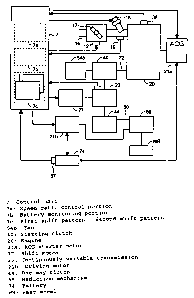
FIG. 2 is a block diagram showing a system configuration of the hybrid
vehicle described above. The power unit 11 includes an engine 20, an
ACG starter motor 21a, a continuously variable transmission (power
transmission means) 23, a shift motor 77, a starting clutch 40, a driving
motor 21b, a one-way clutch 44, and a reduction mechanism 69.
Specifically, the ACG starter motor 21a-:functions as an engine starter and
generator. The continuously variable transmission 23 is connected to a
crankshaft 22 and transmits power of the engine 20 to the rear wheel WR.
The shift motor 77 serves as a shift actuator that changes a shift position of
the continuously variable transmission 23. The starting clutch 40 connects
or disconnects power transmission between the crankshaft 22 and an input
shaft of the continuously variable transmission 23. The driving motor 21b
functions as a motor or a generator. The one-way clutch 44 transmits
power from the engine 20 and the driving motor 21b to the rear wheel
WR, but not from the rear wheel WR to the engine 20. The reduction
mechanism 69 transmits an output from the continuously variable
transmission 23 at a reduced speed to the rear wheel WR. An engine
speed sensor 36 detects an engine speed Ne of the engine 20.
Power from the engine 20 is transmitted from the crankshaft 22 to the rear
wheel WR via the starting clutch 40, the continuously variable
transmission 23, the one-way clutch 44, a driving shaft 60, and the
reduction mechanism 69. Power from the driving motor 21b, on the other
hand, is transmitted to the rear wheel WR via the driving shaft 60 and the
reduction mechanism 69. That is, according to the preferred embodiment
of the present invention, the driving shaft 60 serves as an output shaft of
the driving motor 21b.
WH 12664/cs
. ,a
CA 02508971 2005-06-O1
-9-
A battery 74 is connected to the ACG starter motor 21a and the driving
motor 21b. When the driving motor 21b functions as a motor, and when
the ACG starter motor 21a functions as a starter, the battery 74 supplies
power to the ACG starter motor 21a and the driving motor 21b. When the
ACG starter motor 21a and the driving motor 21b function as a generator,
the battery 74 is recharged by regenerative power generated by the ACG
starter motor 21a and the driving motor 21b. A voltage sensor 37 detects a
terminal data Vbat of the battery.
A throttle valve 17 for controlling the amount of air is rotatably mounted
in an intake pipe 16 of the engine 20. The throttle valve 17 is rotated
according to the amount of operation of a throttle grip (not shown)
operated by the rider. The shift control apparatus according to the
preferred embodiment of the present invention may include a DBW
(drive-by-wire) system 12. The throttle valve 17 can thereby be
automatically controlled according to the engine speed, a vehicle speed,
and the like, irrespective of the operation performed by the rider. A n
injector 18 and a vacuum sensor 19 are disposed between the throttle
valve 17 and the engine 20. The injector 18 injects fuel. The vacuum
sensor 19 detects a negative pressure in the intake pipe.
A control unit 7 includes a gear ratio control portion 7a, a battery
monitoring portion 7b, and a shift pattern registration portion 7c. The
gear ratio control portion 7a controls the shift motor 77 such that the gear
ratio of the continuously variable transmission 23 exhibits a
predetermined shift pattern. The battery monitoring portion 7b
determines a charge state of the battery 74 based on the battery voltage Vbat
detected by the voltage sensor 37. The shift pattern registration portion 7c
stores the shift pattern of the continuously variable transmission 23
previously registered therein.
The construction of the power unit 11 including the engine 20 and the
driving motor 21b will be described with reference to FIG. 3.
The engine 20 includes a piston 25 connected to the crankshaft 22 via a
connecting rod 24. The piston 25 can slide inside a cylinder 27 disposed i n
WH 12664/cs
~ . ... '
CA 02508971 2005-06-O1
-10-
a cylinder block 26. The cylinder block 26 is disposed such that an axis of
the cylinder 27 runs substantially horizontally. A cylinder head 28 is
secured to a front surface of the cylinder block 26. The cylinder head 28,
the cylinder 27, and the piston 25 constitute a combustion chamber 20a for
burning an air-fuel mixture.
The cylinder head 28 includes a valve (not shown) for controlling intake
or exhaust of the air-fuel mixture to or from the combustion chamber 20a,
and an ignition plug 29. Opening or closing of the valve is controlled
through rotation of a camshaft 30 journaled on the cylinder head 28. A
driven sprocket 31 is mounted on one end of the camshaft 30. An endless
cam chain 33 is wound around the driven sprocket 31 and a drive sprocket
32 disposed on one end of the crankshaft 22. A water pump 34 for cooling
the engine 20 is mounted on the one end of the camshaft 30. The water
pump 34 is mounted such that a rotational axis 35 thereof rotates
integrally with the camshaft 30. Accordingly, rotating the camshaft 30
operates the water pump 34.
A stator case 49 is connected on the right-hand side in a vehicle width
direction of a crankcase 48 that journals the crankshaft 22. The ACG
starter motor 21a is housed in the stator case 49. The ACG starter motor
21a is what is called an outer rotor type. A stator of the ACG starter motor
21a includes a coil 51 which is a conductive wire wound around teeth 50
secured to the stator case 49. An outer rotor 52 is, on the other hand,
secured to the crankshaft 22. The outer rotor 52 is of a substantially
cylindrical shape covering an outer periphery of the stator. A magnet 53 is
disposed on an inner peripheral surface of the outer rotor 52.
The outer rotor 52 includes a fan 54a for cooling the ACG starter motor
21a. When the fan 54a rotates in synchronism with the crankshaft 22, a
cooling air is drawn in through a cooling air intake port formed in a side
surface 55a of a cover 55 of the stator case 49. The cooling air is drawn i n
in this manner.
A transmission case 59 is connected to the left-hand side in the vehicle
width direction of the crankcase 48. A fan 54b, the continuously variable
transmission 23, and the driving motor 21b are housed in the
WH 12664/cs
,..
CA 02508971 2005-06-O1
-11-
transmission case 59. The fan 54b is secured to a left end portion of the
crankshaft 22. A driving side of the continuously variable transmission 23
is connected to the crankshaft 22 via the starting clutch 40. The driving
motor 21b is connected to a driven side of the continuously variable
transmission 23. The fan 54b functions to cool the continuously variable
transmission 23 and the driving motor 21b housed in the transmission
case 59. The fan 54b is disposed on the same side as the driving motor 21b
relative to the continuously variable transmission 23, that is, on the left-
hand side in the vehicle width direction according to the preferred
embodiment of the present invention.
A cooling air intake port 59a is formed forward and on the left of the
vehicle body of the transmission case 59. When the fan 54b rotates i n
synchronism with the crankshaft 22, an outside air is drawn in through
the cooling air intake port 59a located near the fan 54b. The driving motor
21b and the continuously variable transmission 23 are forcedly cooled by
the outside air thus drawn in.
The continuously variable transmission 23 is a belt converter including a
driving side transmission pulley 58 and a driven side transmission pulley
62 with an endless V-belt (endless belt) 63 wound therearound. The
driving side transmission pulley 58 is mounted via the starting clutch 40
at a left end portion of the crankshaft 22 protruding in the vehicle width
direction from the crankcase 48. The driven side transmission pulley 62 is
mounted via the one-way clutch 44 on the driving shaft 60 journaled with
an axis running parallel with the crankshaft 22 on the transmission case
59.
Referring to FIG. 4 that is an enlarged view showing a principal part, the
driving side transmission pulley 58 is circumferentially rotatably mounted
on the crankshaft 22 via a sleeve 58d. The driving side transmission
pulley 58 includes a driving side fixed pulley half 58a and a driving side
movable pulley half 58c. The driving side fixed pulley half 58a is fixed to
the sleeve 58d. The driving side movable pulley half 58c is mounted o n
the sleeve 58d such that the pulley half 58c is axially slidable, but unable
to
make a circumferential rotation relative to the sleeve 58d. A shift ring 57
WH 12664/cs
,.
CA 02508971 2005-06-O1
-12-
is rotatably mounted via a bearing 56 to the driving side movable pulley
half 58c.
The shift ring 57 includes a gear 61 formed circumferentially on an outer
peripheral large diameter portion thereof. The shift ring 57 also includes a
trapezoidal screw 65 formed axially on an inner periphery thereof. A
trapezoidal screw 67 meshes with the trapezoidal screw 65. The
trapezoidal screw 67 is mounted so as to be circumferentially rotatable
relative to the sleeve 58d via a bearing 66, but unable to slide axially. A
worm wheel 75 meshes with the gear 61 of the shift ring 57. Further, a
worm gear 76 meshes with the worm wheel 75. The worm gear 76 is
connected to a rotational axis of a shift motor 77 for controlling the gear
ratio.
The driven side transmission pulley 62, on the other hands, includes a
driven side fixed pulley half 62a and a driven side movable pulley half
62b. The driven side fixed pulley half 62a circumferentially rotatably
mounted on the driving shaft 60 via a sleeve 62d, while being restricted i n
its axial sliding motion relative to the driving shaft 60. The driven side
movable pulley half 62b is axially slidably mounted on the sleeve 62d.
An endless V belt 63 is wound around each of belt grooves having
substantially a V-shaped cross section formed between the driving side
fixed pulley half 58a and the driving side movable pulley half 58c, and
between the driven side fixed pulley half 62a and the driven side movable
pulley half 62b.
A spring (elastic member) 64 is disposed on the backside (on the left-hand
side in the vehicle width direction) of the driven side movable pulley half
62b. The spring 64 urges the driven side movable pulley half 62b toward
the driven side fixed pulley half 62a at all times.
When the gear ratio of the automatic transmission 23 is to be changed, the
shift motor 77 is driven in a direction of rotation corresponding to an
upshift or downshift of the gear ratio. The driving force of the shift motor
77 is transmitted to the gear 61 of the shift ring 57 through the worm gear
76 and the worm wheel 75. The shift ring 57 is thereby rotated. Since the
WH 12664/cs
..__.., _. , . _ . , . .
CA 02508971 2005-06-O1
-13-
shift ring 57 is in mesh with the sleeve 57d through the trapezoidal screws
65, 67, the shift ring 57 moves to the left in FIG. 4 along the crankshaft 22.
This results in the driving side movable pulley half 58c sliding toward the
side of the driving side fixed pulley half 58a. The driving side movable
pulley half 58c then comes closer to the driving side fixed pulley half 58a
by the amount of this sliding motion. This decreases a groove width of
the driving side transmission pulley 58. A position of contact between the
driving side transmission pulley 58 and the V belt 63 is then deviated
radially outwardly the driving side transmission pulley 58, causing a
winding diameter of the V belt 63 to increase. This results in the
following occurring in the driven side transmission pulley 62.
Specifically, a groove width formed by the driven side fixed pulley half 62a
and the driven side movable pulley half 62b increases. That is, the
winding diameter of the V belt 63 (a transmission pitch diameter)
continuously varies according to the speed of the crankshaft 22. This
results in the gear ratio being automatically and steplessly varied.
The starting clutch 40 includes an outer case 40a, an outer plate 40b, a
weight 40c, a shoe 40d, and a spring 40e. The outer case 40a of a cup shape
is fixed to the sleeve 58d. The outer plate 40b is fixed on a left end portion
of the crankshaft 22. The shoe 40d is mounted on an outer peripheral
portion of the outer plate 40b via the weight 40c so as to face radially
outwardly. The spring 40e urges the shoe 40d radially inwardly.
When the engine speed, or the speed of the crankshaft 22 is equal to, or
less than, a predetermined value (e.g., 3000 rpm), power transmission
between the crankshaft 22 and the continuously variable transmission 23
is disconnected through the starting clutch 40. As the engine speed
increases and the speed of the crankshaft 22 exceeds the predetermined
value, the centrifugal force acting on the weight 40c counteracts an elastic
force acting radially inwardly by the spring 40e, moving the weight 40c
radially outwardly. This causes the shoe 40d to press an inner peripheral
surface of the outer case 40a with a force of a predetermined value or
more. This causes rotation of the crankshaft 22 to be transmitted to the
sleeve 58d via the outer case 40a. The driving side transmission pulley 58
fixed to the sleeve 58d is thereby driven.
WH 12664/cs
,....a .,. .
CA 02508971 2005-06-O1
-14-
The one-way clutch 44 includes an outer clutch 44a, an inner clutch 44b,
and a roller 44c. The outer clutch 44a is of a cup shape. The inner clutch
44b is internally inserted in the outer clutch coaxially therewith. The
roller 44c allows power to be transmitted in one direction only from the
inner clutch 44b to the outer clutch 44a. The outer clutch 44a serves also as
an inner rotor main body for the driving motor 21b. The outer clutch 44a
is formed of the same member as the inner rotor main body.
Power from the side of the engine 20 transmitted to the driven side
transmission pulley 62 of the continuously variable transmission 23 is
transmitted to the rear wheel WR by way of the driven side fixed pulley
half 62a, the inner clutch 44b, the outer clutch 44a or the inner rotor main
body, the driving shaft 60, and the reduction mechanism 69. Power from
the side of the rear wheel WR generated as the vehicle is pulled by
walking, during regenerative operation, or the like, on the other hand, is
transmitted to the reduction mechanism 69, the driving shaft 60, and the
inner rotor main body or the outer clutch 44a. The power generated in the
latter case is not, however, transmitted to the continuously variable
transmission 23 and the engine 20, since the outer clutch 44a turns idly
relative to the inner clutch 44b.
The driving motor 21b of an inner rotor type is disposed rearward of the
transmission case 59. The driving motor 21b uses the driving shaft 60 as
its output shaft. An inner rotor 80 includes the driving shaft 60, an inner
rotor main body or the inner clutch 44b, and a magnet. The driving shaft
60 serves also as an output shaft for the continuously variable
transmission 23. The inner clutch 44b is in splined engagement with the
driving shaft 60 by a cup-shaped boss portion 80b formed at a central
portion thereof. The magnet is disposed on an outer peripheral surface on
an open side of the inner clutch 44b.
Referring back to FIG. 3, the reduction mechanism 69 is disposed in a
transmission chamber 70 that continues to the right-hand side at a trailing
end portion of the transmission case 59. The reduction mechanism 69
includes an intermediate shaft 73 that is journaled in parallel with the
driving shaft 60 and an axle 68 of the rear wheel WR. The reduction
mechanism 69 further includes a pair of first reduction gears 71 and a pair
WH 12664/cs
~,......k . ,.. ,
CA 02508971 2005-06-O1
-15-
of second reduction gears 72. The first reduction gears 71 are formed on a
right end portion of the driving shaft 60 and a central portion of the
intermediate shaft 73, respectively. The second reduction gears 72 are
formed on the intermediate shaft 73 and a left end portion of the axle 68,
respectively. Through such an arrangement, the speed of rotation of the
driving shaft 60 is reduced at a predetermined reduction ratio. Rotation of
the driving shaft 60 is then transmitted to the axle 68 of the rear wheel
WR that is journaled in parallel with the driving shaft 60.
In the hybrid vehicle having the arrangements as described in the
foregoing, the ACG starter motor 21a mounted on the crankshaft 22 is
used to turn the crankshaft 22 when the engine is to be started. At this
time, the starting clutch 40 is not engaged, meaning that power
transmission from the crankshaft 22 to the continuously variable
transmission 23 is shut off.
When the throttle grip is operated and opened, only the driving motor 21b
provides power as long as a throttle opening 8th remains small according
to the preferred embodiment of the present invention. Rotation of the
driving shaft 60 through the driving motor 21b is not transmitted to the
driven side transmission pulley 62 through the functioning of the one
way clutch 44. The continuously variable transmission 23 can then never
be driven. Accordingly, running the vehicle by driving the rear wheel
WR only with the driving motor 21b enhances energy transmission
efficiency.
As the throttle opening 8th is made greater, the engine speed increases.
When the speed of the crankshaft 22 thereafter exceeds a predetermined
value (e.g., 3000 rpm), the rotational power of the crankshaft 22 is
transmitted to the continuously variable transmission 23 through the
starting clutch 40 and applied to the one-way clutch 44. When the speed
on an input side of the one-way clutch 44 coincides with the speed on an
output side thereof, that is, the driving shaft 60, power is switched from
the driving motor 21b to the engine 20.
FIG. 5 is a diagram showing a typical shift pattern according to the first
preferred embodiment of the present invention. In FIG. 5, a broken line
WH 12664/cs
w..~....... .. w~ . ..",~....,u...
r_~w,.
CA 02508971 2005-06-O1
-16-
represents a shift pattern (a first pattern) when the remaining charge of the
battery 74 is sufficient, while a solid line represents a shift pattern (a
second pattern) when the remaining charge of the battery 74 is insufficient.
According to the preferred embodiment of the present invention, if it is
determined that the remaining charge of the battery is insufficient, a low
ratio control range is expanded to include a high engine speed side. The
gear ratio with an insufficient remaining charge of the battery 74 is thereby
made lower than the gear ratio with a sufficient remaining charge of the
battery 74 particularly in a medium speed running range.
FIG. 6 is a flowchart showing shift pattern control processes that change
the shift pattern based on a remaining charge M of the battery 74. FIG. 6
mainly shows operations performed by the control unit 7.
In step S1, the battery monitoring portion 7b detects the remaining charge
M of the battery 74 based on the battery voltage Vbat detected by the
voltage sensor 37 or a record thereof. In step S2, it is determined whether
the vehicle is in a stationary state based on, for example, a vehicle speed V.
If it is determined that the vehicle is in the stationary state, the control
proceeds to step S3. In step S3, the remaining charge M of the battery 74 is
compared with a reference remaining charge Mref that has previously
been registered as a threshold value of changing the shift pattern. If the
remaining charge M of the battery 74 is lower than the reference
remaining charge Mref, the control proceeds to step S4. In step S4, it is
determined that the current shift pattern is the first pattern (the shift
pattern indicated by the broken line in FIG. 5) adopted when the
remaining charge is sufficient or the second pattern (the shift pattern
indicated by the solid line in FIG. 5) adopted when the remaining charge is
insufficient. If the current pattern is one other than the second pattern,
the control proceeds to step S5. In step S5, the shift pattern is changed
from the current first pattern to the second pattern. Accordingly,
following this step, the gear ratio is controlled according to the second
pattern indicated by the solid line in FIG. 5.
WH 12664/cs
. fi . ~ .. . .... .
m.._..4 ..... ,~ , , .. .
CA 02508971 2005-06-O1
-17-
If, in step S3, it is not determined that the remaining charge M of the
battery 74 is lower than the reference remaining charge Mref, the control
proceeds to step S6. In step S6, it is determined that the current shift
pattern is the first pattern or the second pattern. If the current pattern is
one other than the first pattern, the control proceeds to step S7. In step S7,
the shift pattern is changed from the current second pattern to the first
pattern.
As described in the foregoing, according to the first preferred embodiment
of the present invention, the shift pattern is changed from the first pattern
to the second pattern as a result of the remaining charge M of the battery
74 decreasing. Even if this happens, if charging is thereafter promoted to
allow the battery 74 to recover its charge, the shift pattern is returned from
the second pattern to the first pattern. Accordingly, the gear ratio is
hereafter controlled according to the first pattern indicated by the broken
a
line in FIG. 5.
FIG. 7 is a diagram showing a shift pattern according to a second preferred
embodiment of the present invention. In FIG. 7, again, a broken line
represents a shift pattern (a first pattern) when the remaining charge of the
battery 74 is sufficient, while a solid line represents a shift pattern (a
second pattern) when the remaining charge of the battery 74 is insufficient.
According to the second preferred embodiment of the present invention,
if it is determined that the remaining charge M of the battery 74 is
insufficient, a gear ratio in the low ratio control range Rlow is lowered
further than the level when it is determined that the remaining charge M
of the battery 74 is sufficient. The gear ratio when the remaining charge M
of the battery 74 is insufficient is thus made to be lower than the gear ratio
when the remaining charge M of the battery 74 is sufficient particularly i n
a low speed running range.
FIG. 8 is a diagram showing a shift pattern according to a third preferred
embodiment of the present invention. In FIG. 8, too, a broken line
represents a shift pattern (a first pattern) when the remaining charge of the
battery 74 is sufficient, while a solid line represents a shift pattern (a
second pattern) when the remaining charge of the battery 74 is insufficient.
WH 12664/cs
a~., .. ...." . ~ _..~.. __. ...
.~...~ .,. , .. . .
CA 02508971 2005-06-O1
-18-
According to the third preferred embodiment of the present invention,
the lower the remaining charge M of the battery 74, the more the gear ratio
in the low ratio control range Rlow is shifted to the low ratio side as in the
second preferred embodiment of the present invention. At the same time,
the low ratio control range is expanded to include the high engine speed
side as in the first preferred embodiment of the present invention. The
gear ratio when the remaining charge M of the battery 74 is insufficient is
thereby made to be lower than the gear ratio when the remaining charge
M of the battery 74 is sufficient in both the low speed running range and
the medium speed running range.
The present invention is not limited to the above embodiments in which
the second shift pattern is selected when the remaining charge of the
battery becomes insufficient. It is nonetheless appropriate that a plurality
of shift patterns adopted according to the degree of insufficiency of the
remaining charge of the battery be provided and the optimum shift
pattern be adopted according to the remaining charge of the battery. A n
arrangement can thereby be made to control the shift pattern such that an
even lower gear ratio can be selected when insufficiency of the remaining
charge of the battery is serious.
Although various preferred embodiments of the present invention have
been described herein in detail, it will be appreciated by those skilled in
the
art, that variations may be made thereto without departing from the spirit
of the invention or the scope of the appended claims.
WH 12664/cs
... . .f... . . . ..... .. ..