Note: Descriptions are shown in the official language in which they were submitted.
CA 02509929 2005-06-13
WO 2004/055338 PCT/CA2003/001764
FLUID FLOW ACTUATED FLAPPER VALVE
FIELD OF THE INVENTION
[0001] The field of the invention is in the area of valves
for controlling the fluid flow in a conduit, and
particularly relates to a flow actuated valve for
controlling fluid flow in a conduit of cooling systems of
aircraft gas turbine engines.
BACKGROUND OF THE INVENTION
[0002] Electrical and mechanical equipment often requires
cooling while in operation. Both liquid (e.g. oil) and gas
(e.g. air) cooling schemes are well known. Air cooling
schemes may be either active (e.g. fan driven) or passive
(i.e. rely on an existing pressure gradient to introduce a
flow of cooling air to the equipment). In gas turbine
engine applications employing a passive air cooling scheme
to cool the on-board generator(s),. a minimum amount of
airflow is required to cool the generator. A pipe that is
attached to the bypass duct on the gas turbine engine has
been sized to allow this minimum mass flow of air when the
air pressure difference between the bypass duct and the
atmosphere is very small, for example approximately 2 lbs.
per square inch differential (PSID). This is the condition
at idle of the gas turbine engine when the aircraft is on
the ground. When the engine speed is increased for takeoff
or flight conditions, the pressure difference between the
bypass duct and atmosphere is increased to approximately 10
PSID. This causes more cooling air than is required to
cool the generator, to flow through the pipe. The
resulting oversupply of cooling air increases the Specific
Fuel Consumption (SFC) of the gas turbine engine.
Therefore it is desirable to use a valve to control the
SUBSTITUTE SHEET (RULE 26)
CA 02509929 2005-06-13
WO 2004/055338 PCT/CA2003/001764
2 -
cooling airflow through the pipe between the bypass duct
and the generator.
[0003] Fugii describes an automatic airflow smoothing
valve in his United States Patent 3,718,516 issued on
February 27, 1973, for ensuring a constant output flow in
spite of great changes of the pressure of the input
airflow. Fugii's valve includes a hollow, elongated
open-ended casing, and a rod is mounted in the upper end of
the casing and depends therealong. A primary coiled
extension spring is mounted on the rod and a pair of
secondary coiled extension springs are attached at their
upper ends to the primary coiled extension spring to form a
star connection. A pair of flapper disc halves hinged
together are pivotally mounted within the casing at the
lower end thereof. The lower ends of the secondary coiled
extension springs diverge from the primary coiled extension
spring and are attached to the respective flapper disc
halves. Perforations are provided in the flapper disc
halves to permit airflow when the valve is closed against
the spring forces by the input airflow under relatively
high pressure. When the pressure of the input airflow is
reduced, the extended springs cause the valve to open to an
extent corresponding to the pressure of the input airflow,
in order to ensure the constant output airflow.
[0004] Smirra describes a hinge valve in his United States
Patent 3,559,679, issued on February 2, 1971 for
controlling fluid flow in a conduit. Smirra's valve
comprises a support member extending diametrically across
the interior of the conduit. Two flap members pivotally
mounted to the support member are adapted to move from an
SUBSTITUTE SHEET (RULE 26)
CA 02509929 2005-06-13
WO 2004/055338 PCT/CA2003/001764
3 -
open position allowing flow of fluid through the conduit to
a closed position preventing flow of fluid. The flap
members are actuated by a piston that is pivotally attached
to linkage connecting the flap members and moves within a
hydraulic cylinder under fluid pressure or spring force.
Both Fugii's and Smirra's valves are complicated and
include more moving parts than the two flap members, which
compromises the reliability of their valves. Both Fugii's
and Smirra's valves include coiled extension or compression
springs positioned axially within the casing or the
conduit, which cause the corresponding parts to move
axially such that the valves cannot be made compact in the
axial dimension.
[0005] The cooling system of an aircraft gas turbine
engine requires a valve that does not necessarily maintain
a constant output volume of airflow, but must be very
reliable in performance, and compact in size to reduce the
weight thereof. Therefore, there is a need to develop an
improved valve to be used in the cooling system of aircraft
gas turbine engines, in order to control the cooling airflow
to the generator.
SUMMARY OF THE INVENTION
[0006] One object of the present invention is to provide a
fluid flow actuated valve for controlling the fluid flow in
a conduit, which is compact in size, light in weight and
reliable in performance.
[0007] In accordance with one aspect of the present
invention, a fluid flow actuated valve for controlling the
fluid flow in a conduit comprises a support structure
SUBSTITUTE SHEET (RULE 26)
CA 02509929 2005-06-13
WO 2004/055338 PCT/CA2003/001764
4 -
adapted to be mounted within the conduit. At least one
flap member is pivotally mounted to the support structure
and is pivotable between a first position for a minimum
fluid flow passage and a second position for a maximum
fluid flow passage. A torsion spring is attached to the at
least one flap member to urge the same to pivot against a
fluid pressure differential from the first position to the
second position when the fluid pressure differential is
smaller than a predetermined level. It should be noted
that for the purpose of this specification and the appended
claims, the term "minimum fluid flow" means a non-zero
fluid flow such that the valve of the present invention is
distinguished from conventional check valves.
[0008] The torsion spring is preferably disposed such that
an axis of torsion spring is superposed on a pivoting axis
of the at least one flap member. For example, the torsion
spring can be a coiled torsion spring surrounding a shaft
on which the at least one flap member is pivotally mounted.
[0009] In accordance with another aspect of the present
invention, a fluid flow actuated valve is provided for
controlling the fluid flow in a conduit. The valve
includes a support ring adapted to be mounted within the
conduit. Two flap members are pivotally mounted to the
support ring, respectively, and are pivotable between a
first position for a minimum fluid flow passage and a
second position for a maximum fluid flow passage. Spring
means including at least one or more springs are disposed
in a position in=which an axial axis of each spring is
substantially perpendicular to an axial axis of the support
ring. The spring means urge the flap members against the
SUBSTITUTE SHEET (RULE 26)
CA 02509929 2005-06-13
WO 2004/055338 PCT/CA2003/001764
-
fluid pressure differential smaller than a predetermined
level, to pivot from the first position to the second
position. The spring means permit the flap members under a
fluid pressure differential not smaller than the
predetermined level, to pivot from the second position to
the first position.
[0010] The flap members in the first position preferably
extend transversely across the support ring while forming
the minimum flow passage. The respective flap members in
the second position preferably extend axially and radially
with respect to the support ring such that the valve is
open to form the maximum fluid flow passage
[0011] In one embodiment of the present invention, a shaft
diametrically extends across the support ring and is
secured thereto. The respective flap members are pivotally
mounted to the shaft. The at least one spring is attached
to the respective flap members to urge the flap members to
pivot towards each other until the respective flap members
are stopped in an angularly spaced-apart position by a
spacer secured to the respective flap members.
[0012] In another embodiment of the present invention the
support ring includes a pair of pivoting pins secured to
the support ring at diametrically opposed positions
thereon. The pair of pivoting pins are parallel with and
symmetrical about a diametrical line of the support ring.
The flap members are pivotally mounted to the respective
pivoting pins, and are urged to pivot away from each other
by the spring means until the flap members arrive in the
second position.
SUBSTITUTE SHEET (RULE 26)
CA 02509929 2005-06-13
WO 2004/055338 PCT/CA2003/001764
6 -
[0013] The fluid flow actuated valve of the present
invention is simple in configuration and has fewer moving
parts in contrast to the prior art valves, and thereby
advantageously ensures reliability in performance, in order
to meet the requirements of gas turbine engines used in
aircraft. The fluid flow actuated valve of the present
invention is advantageously light in weight, and compact in
size particularly in the axial dimension. The axial
dimension of such valves can be made substantially smaller
than the diameter of the conduit within which the valves
are installed, such that the valves of the present
invention can fit between the bypass duct and the cooling'
pipe to the generator without obstructing the bypass flow.
[0014] In accordance with a further aspect of the present
invention, a passive air cooling apparatus for an aircraft-
mounted gas turbine engine and an aircraft-mounted gas
turbine engine having such a passive air cooling apparatus
are provided. The gas turbine engine has an airflow passing
therethrough. The passive air cooling apparatus comprises a
conduit adapted to divert a cooling airflow from the
airflow to at least a portion of an engine system to be
cooled. A valve is disposed in the conduit and is
positionable between a first position in which the cooling
airflow through the conduit is partially blocked by the
valve, and a second position in which the cooling airflow
is substantially unblocked by the valve. The valve is
biased towards the second position. When a pressure
differential sufficient to overcome the biasing of the
valve towards the second position is applied across the
valve in the conduit, the valve is moved by the pressure
differential to the first position.
SUBSTITUTE SHEET (RULE 26)
CA 02509929 2005-06-13
WO 2004/055338 PCT/CA2003/001764
7 -
[0015] Other features and advantages of the present
invention will be better understood with reference to the
preferred embodiments described hereinafter.
BRIEF DESCRIPTION OF THE DRAWINGS
[0016] Having thus generally described the nature of the
present invention, reference will now be made to the
accompanying drawings, showing by way of illustration the
preferred embodiments thereof, in which:
[0017] Fig. 1 is a schematic illustration in a partial
cross-sectional view, showing an aircraft gas turbine
engine incorporating a valve of the present invention;
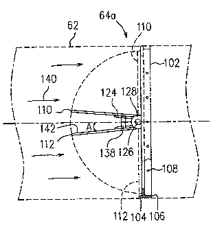
[0018] Fig. 2 is a plan view of a valve according to one
embodiment of the present invention, showing the valve in a
closed position forming a-minimum airflow passage;
[0019] Fig. 3 is an elevational side view of the
embodiment of Fig. 2, showing the valve in an open position
forming a maximum airflow passage;
[0020] Fig. 4 is a plan view - of a valve according to
another embodiment of the present invention, showing the
valve in a closed position forming a minimum airflow
passage;
[0021] Fig. 5 is an elevational side view of the
embodiment of Fig. 4, showing the valve in an open position
forming a maximum airflow passage;
[0022] Figs. 6a and 6b are plan views of the respective
flap members used in the embodiment of Fig. 2;
SUBSTITUTE SHEET (RULE 26)
CA 02509929 2005-06-13
WO 2004/055338 PCT/CA2003/001764
8 -
[0023] Fig. 7 is a partial cross-sectional view taken
along line 7-7 in Fig. 6a;
[0024] Fig. 8a is a partial cross-sectional view taken
along line 8a-8a in Fig. 4;
[0025] Fig. 8b is a partial plan view' of one of the flap
members used in the embodiment of Fig. 4;
[0026] Fig. 8c is a cross-sectional view taken along
.line 8c-8c in Fig. 8b, showing a bracket used in the
embodiment of Fig. 4 for supporting a pivoting pin; and
[0027] Figs. 9a and 9b are partial cross-sectional views
of a conduit with the valves installed therein according to
further alternative embodiments of the present invention.
[0028] Figs. 9c and 9d are cross-sectional views of a
section of a conduit with the valves installed therein
according to still further alternative embodiments of the
present invention.
DETAILED DESCRIPTION OF THE PREFERRED EMBODIMENTS
[0029] Referring to the drawings, particularly Fig. 1, an
exemplary aircraft gas turbine engine 10 includes in serial
flow communication about.a longitudinal centerline axis 12,
a fan having a plurality of circumferentially spaced apart
fan blades 14, a low pressure compressor 16, a high
pressure compressor 18, an annular combustor 20, a high
pressure turbine 22 and a low pressure turbine 24. The low
pressure turbine 24 is securely connected to both the low
pressure compressor 16 and the fan blades 14 by a first
rotor shaft 26, and the high pressure turbine 22 is
SUBSTITUTE SHEET (RULE 26)
CA 02509929 2010-12-14
CA 02509929 2005-06-13
WO 20041055338 PCT/CA2003/001764
- 9 -
securely connected to the high pressure compressor 18 by a
second rotor shaft 28. Fuel injecting means 30 are
provided for selectively injecting fuel into the
combustor 20 for powering the engine 10.
[0030] An annular casing 32 surrounds the engine 10 from
the low pressure compressor 16 to the low pressure
turbine 24 and defines, with the low pressure
compressor 16, a low pressure compressor inlet 34 for
receiving a portion of ambient air 36. The downstream end
of the casing 32 defines with an annular exhaust plug 40,
an annular exhaust outlet 42. A portion of the air 36
compressed by the fan blades 14 adjacent to blade roots 38,
is further compressed by the low pressure compressor 16 and
the high pressure compressor 18 and is forced into the
combustor 20. The mixture of the compressed air 36 and the
fuel injected by the fuel injecting means 30 generates
combustion gases 52. The combustion gases 52 cause the
high pressure turbine 22 and the low pressure turbine 24 to
rotate respectively for powering the high pressure
compressor 18, low pressure compressor 16 and the fan
blades 14.
[0031] A nacelle 44 is provided to surround the engine and
forms an annular bypass duct 55. (Figure 1 shows a
"short-cowl" nacelle, but it will be recognized that a
"long-cowl" nacelle could also be used). The annular
bypass duct 55 is defined by an outer bypass duct wall 53
which is an inner periphery of the nacelle 44, and an inner
bypass duct wall 51 which is a portion of the engine
casing 32. A radially outer portion of the air 36
compressed by the fan blades 14 bypasses the engine through
SUBSTITUTE SHEET (RULE 26)
CA 02509929 2005-06-13
WO 2004/055338 PCT/CA2003/001764
- 10 -
the bypass duct 55. A plurality of circumferentially
spaced intercase struts 46 extend radially between the
inner and' outer bypass duct walls 51 and 53. The
nacelle 44 includes an inlet 48 at its upstream end for
receiving the ambient air 36, and an outlet 50 for
discharging a portion of the air 36 compressed by the fan
blades 14 past the bypass duct 55, for providing a portion
of thrust. A generator 56 (in this case, a direct current
DC generator is used, though an alternating current AC
generator may also be used) and a gear box 58 are installed
in the nacelle 44 and disposed outside the outer bypass
duct wall 53. A power shaft which is schematically
illustrated by a broken line 60 transmits torque from the
engine shaft 26 to the gear box 58 for driving the
connected generator 56. A cooling conduit 62 is provided
in fluid communication with the bypass duct 55 and the
generator 56, to deliver cooling air to cool the
generator 56.
[0032] In the prior art, the cooling air through the
conduit 62 is not controlled and the conduit 62 is designed
to deliver a minimum air mass flow necessary for cooling
the generator 56 when the engine 10 is idling and the flow
pressure difference between the two ends of the conduit 62
is relatively small. However, the amount of cooling air
passing through the conduit 62 is much greater than
necessary for cooling the generator 56 when the engine 10
is at a high setting for take-off and cruise of aircraft,
and the flow pressure difference between the two ends of
the conduit 62 is significantly increased, which causes
thrust loss and fuel waste. In order to solve this
problem, a flapper valve 64 of the present invention is
SUBSTITUTE SHEET (RULE 26)
CA 02509929 2005-06-13
WO 2004/055338 PCT/CA2003/001764
- 11 -
installed in the conduit 62 to control the cooling air
delivered to the generator 56 when the engine 10 changes
its setting. The flapper valve 64 is described in detail
below.
[0033] In Figs. 2 and 3 a flapper valve 64a according to
one embodiment of the present invention includes a support
structure having a support ring 102. The support ring 102
has a diameter slightly smaller than the inner diameter of
the conduit 62, which is shown by broken lines in Fig. 3,
such that the support ring 102 can be fitted within
conduit 62. The support ring 102 includes an annular
radial surface 104 and an annular flange 106 axially
extending from the radial surface 104 to form an external
periphery of the support ring 102. A plurality of mounting
holes 108 on the flange 106 receive mounting screws (not
shown) to secure the valve 64a to the conduit 62.
[0034] A pair of flap members 110 and 112 are pivotally
mounted to the support ring 102. The respective flap
members 110 and 112 are generally halves of a circular
plate, as shown in Fig. 2. The flap member 110 which is
more clearly illustrated in Fig. 6a, includes a
substantially semi-circular plate 114 and two sleeve
members 116 attached to or integrally formed with the
plate 114. The two sleeve members 116 are spaced apart
from each other and have their holes 118 (see Fig. 7)
aligned with each other. Similarly to flap member 110 and
as more clearly shown in Fig. 6b, flap member 112 includes
a substantially semi-circular plate 120 and two sleeve
members 122 which are spaced apart and aligned with each
other. The space between the two sleeve members 122 of the
SUBSTITUTE SHEET (RULE 26)
CA 02509929 2005-06-13
WO 2004/055338 PCT/CA2003/001764
- 12 -
flap member 112 is selected to accommodate a coiled torsion
spring 124. The space between the sleeve members 116 of
the flap member 110, is much greater than the space between
sleeve members 122 of the flap member 112, in order to
accommodate the two sleeve members 122 and the coiled
torsion spring 124 so as to form a complete circular plate
adapted to extend across the support ring 102 when the flap
members 110 and 112 are pivotally mounted to the support
ring 102, as shown in Fig. 2.
[0035] Referring again to Fig. 2 and 3, a shaft 126
extends diametrically across the support ring 102 and is
mounted to the annular, radial surface 104 by a pair of
support plates, or lugs, 128. Alternately, shaft 126 can
be press fit into support ring 102. The sleeve members 116
of the flap member 110 and sleeve members 122 of the flap
member 112, as well as the coiled torsion spring 124, are
rotatably received on the shaft 126. Thus, the flap
members 110 and 112 are pivotable about the shaft 126
between an open position as shown in Fig. 3 and a closed
position as shown in Fig. 2. The closed position is also
shown in broken lines in Fig. 3. Each flap member 110
and 112 has cut-outs 130 at their respective corners (more
clearly shown in Figs. 6a and 6b) to accommodate the
support plates 128 in order to avoid interference with the
pivoting movement of the respective flap members 110
and 112.
[0036]A torsion spring can be twisted by a torque and the
twisted torsion spring will recover its original
configuration when the applied torque is removed. The
coiled torsion spring 124 used in this embodiment includes
SUBSTITUTE SHEET (RULE 26)
CA 02509929 2010-12-14
CA 02509929 2005-06-13
WO 2004/055338 PCT/CA2003/001764
- 13 -
a first end 132 and a second end 134 which are attached to
the respective flap members 110 and 112 by bracket 136.
The brackets 136 are secured to the respective flap
members 110 and 112 by well known means, for example screws
(not shown). The coiled torsion spring 124 is pre-twisted
when it is installed in the valve 64a such that the coiled
torsion spring 124 urges the flap members 110 and 112 to
pivot towards each other until the pivotal movement thereof
is stopped by two stop members 138 as shown in Fig. 3, to
form the open position of the valve 64a. Thus, the
valve 64a functions as a normally open valve. The stop
members 138 are sized and positioned such that the
respective flap member 110 and 112 -extend axially and
radially with respect to the support ring 102 and are
positioned at a predetermined angle A relative to the axial
axis of the support ring 102.
[0037] The valve 64a is installed in the conduit 62 in a
reversed manner such that the flap members 110 and 112 pivot
to open towards the upstream direction of an airflow 140 in
the conduit 62. In such an arrangement, when the pressure
differential of the airflow 140 reaches a predetermined
level, and the force acting on an upstream side 142 of the
respective flap members 110 and 112 caused by the pressure
differential of the airflow 140, is great enough to
overcome the torque produced by the twisted coiled torsion
spring 124, the respective flap members 110 and 112 are
pushed by the airflow 140 to pivot away from each other
until the respective flap members 110 and 112 extend
transversely with respect to the conduit 62 and abut the
annular radial surface 104 of the support ring 102. This
is the closed position of the valve 64a.
SUBSTITUTE SHEET (RULE 26)
CA 02509929 2005-06-13
WO 2004/055338 PCT/CA2003/001764
- 14 -
[0038] The respective flap members 110 and 112 include for
example, an aperture 144 to form air passages,. in order to
permit airflow 140 to pass through the valve 64a when the
flap members 110 and 112 are in their closed position. The
size and number of the apertures 144 are predetermined to
meet the requirements of the minimum cooling airflow mass
for the generator 56 when the gas turbine engine 10 is at a
high setting and the valve 64a is closed.
[0039] The stop members 138 are sized to determine the
angle A such that the open position of the valve 64a meets
the requirements of a maximum cooling airflow for the
generator 56 when the engine 10 is in a lower setting, and
meets the requirements for valve actuation such that the
flap members 110 and 112, are actuated by the airflow 140 at
a predetermined pressure differential level to pivot to
close the valve 64a. The size, number and location of the
apertures 144 also affect the actuation of the flap
members 110 and 112, and therefore the predetermined
airflow pressure differential level is also taken into
consideration when the apertures 144 are designed.
[0040] Thus, the valve 64a eliminates any axially moving
parts and reduces the number of moving parts to a minimum
level, thereby providing a compact configuration and
increasing the reliability, which is required by gas
turbine engines used in aircraft. More specifically, the
compact configuration of valve 64a has an axial dimension
thereof substantially smaller than a diametrical dimension
thereof, which is desirable for use in aircraft gas turbine
engines.
SUBSTITUTE SHEET (RULE 26)
CA 02509929 2010-12-14
CA 02509929 2005-06-13
WO 2004/055338 PCT/CA2003/001764
- 15 -
[0041] Figs. 4 and 5 illustrate another embodiment of the
present invention. A valve 64b according to this
embodiment of the present invention, includes a support
ring 202 which is similar to the support ring 102 of
Fig. 3. The support ring 202 includes an annular radial
surface 204 and an annular flange 206 axially extending
from the radial surface 204 to form an external periphery
of the support ring 202. A plurality of mounting holes 208
on the flange 206 receive mounting screws (not shown) to
secure the valve 64b to the conduit 62.
[0042] Flap members 210 and 212 are pivotally mounted to
the support ring 202 and are pivotable between an open
position as shown in Fig. 5 for the maximum cooling airflow
to the generator 56 of Fig. 1, when the airflow 240 is
smaller than a predetermined pressure differential level,,
and a closed position, as shown in Fig. 4 (also shown by
the broken line of the flap members 210, 212 in Fig. 5) to
form passages to permit a minimum cooling airflow through
the valve 64b when the airflow is not smaller than the
predetermined pressure differential level. In particular,
the flap members 210 and 212 are pivotally mounted on
pivoting pins 226, respectively. The pivoting pins 226 are
secured to the support ring 202 at diametrically opposed
positions thereon. The pivoting pins 226 are parallel with
and symmetrical about a diametrical line 222 of the support
ring 202. The flap members 210 and 212 are identical to
each other and so for simplification of description only
the flap member 210 is described in detail below.
[0043] The flap member 210 is substantially semi-circular
and has a cut-out 214 (see Fig. 8b) to accommodate a coiled
SUBSTITUTE SHEET (RULE 26)
CA 02509929 2005-06-13
WO 2004/055338 PCT/CA2003/001764
- 16 -
torsion spring 224, support brackets 228 as shown in
Figs. 8a to 8c, and two hinge plates 216. The two hinge
plates 216 are attached, for example by welding to the edge
of the cut-out 214 of the flap member 210. The hinge
plates 216 include a hole 218 extending therethrough for
receiving a pivoting pin 226 extending therethrough. The
hinge plates 216 are positioned spaced apart from each
other and spaced apart from the respective two ends of the
cut-out 214 such that the coiled torsion spring 224 which
surrounds the pivoting pin 226 is received between the two
hinge plates 216, and the respective support brackets 228
which are secured to the radial surface 204 of the support
ring 202 are received in the cut-out 214 out of the hinge
plates 216. Each of the support brackets 228 includes a
hole 230 to receive the pivoting pin 226. Thus, the flap
member 210 can freely pivot about the pivoting pin 226
between its open position and the closed position, as shown
by broken lines in Fig. 5. The flap member 210 includes an
aperture 244 to form the air passage for the minimum
cooling airflow when the valve 64b is closed.
[0044] The coiled torsion spring 224 has two ends 232
and 234 (see Fig. 5). One end 232 is attached to the
respective flap members 210 and 212 by a bracket 236 and
the other end 234 is attached to the support ring 202, for
example extending through a hole or notch (not shown) and
abutting the inner periphery of the axial wall 206 of the
support ring 202 as shown in Fig. 5. The coiled torsion
spring 224 is installed in a pre-loaded condition such that
the flap members 210 and 212 are normally urged to their
open position. The diametrical dimension of the two
semi-circular halves of the flap members 210 and 212 must
SUBSTITUTE SHEET (RULE 26)
CA 02509929 2005-06-13
WO 2004/055338 PCT/CA2003/001764
- 17 -
be smaller than the external diameter of the support
ring 202 which is fitted within the conduit 62. The
straight edge of each of the flap members 210 and 212 which
is on the diametrical line 222 of the support ring 202 when
the flap members 210 and 212 are in the closed position as
shown in Fig. 4, move away from this diametrical line 222
in opposite directions. The clearance between the inner
periphery of the conduit 62 and the-respective opposed ends
of the straight edge of the flap member 210 becomes smaller
when the flap members 210 and 212 pivot to open and the
straight edge moves away from the diametrical line 222
because of the circular shape of the inner periphery of the
conduit 62. Thus, the pivotal movement of the flap
members 210 and 212 is restricted to a certain degree by
the inner periphery of the conduit 62, depending on the
amount of clearance. Stoppers 223 preferably stop the
respective flap members 210, 212 before they contact the
inner conduit wall. The stopper shape and position, and
the flapper shape relative to the inner conduit wall may be
adjusted to "tune" the valve in order to meet the desired
maximum cooling airflow. The number and size of the
apertures 244 in the flap members 210 and 212 are
determined in order meet the requirements for the desired
minimum cooling airflow when the valve 64b is closed.
Furthermore, the threshold pressure differential level, at
which the valve is actuated to close, is also considered in
design when the number, size and location of the
apertures 244 and the opening angle of the flap members 210
and 212 are chosen to suit the specific performance
requirements of the valve.
SUBSTITUTE SHEET (RULE 26)
CA 02509929 2010-12-14
CA 02509929 2005-06-13
WO 2004/055338 PCT/CA2003/001764
- 18 -
[0045] Referring to Figs. 2-5 again, the air passage for
the minimum cooling airflow when the valve 64a or 64b is
closed, can be alternatively arranged. The apertures 144
and 244 can be replaced by cut-outs in the flap members, as
for example shown by broken lines 146 and 246.
[0046] In further embodiments illustrated in Figs. 9a
and 9b, the air passage for the minimum cooling airflow
when the valve is closed can be formed as an annular
passage 350 or 450. The annular passage 350 is formed
between the inner periphery of the support ring 302 and the
external periphery of the flap member 310. The support
ring 302 is fitted within the conduit 62 and has a
plurality of stop members 352 circumferentially spaced
apart from one another and extending radially inwardly.
The flap member 310 has a diametrical dimension smaller
than the internal diameter of the support ring 302 and
abuts the plurality of stop members 352 when in its closed
position. The annular passage 450 is formed between the
inner periphery of the conduit 62 and the support ring 402
which is secured within the conduit 62, and is radially
spaced apart therefrom by a plurality of spacers 452.
Thus, when the flap member 410 in its closed position abuts
the support ring 402, the annular passage 450 is left open
for the minimum cooling airflow to pass therethrough.
[0047] Other configurations may be arranged for the
minimum cooling airflow passage when the valve is closed.
The above described are examples only. Other changes may
also be made to the described embodiments of the present
invention. For example in the configuration of the
embodiment illustrated in Figs. 4 and 5, the number of the
SUBSTITUTE SHEET (RULE 26)
CA 02509929 2005-06-13
WO 2004/055338 PCT/CA2003/001764
- 19 -
flap members may change. A substantial circular flap
member can be used to replace the two semi-circular halves
and only one coiled torsion spring is needed. - However,
such an embodiment will increase the axial dimension of the
valve. Three or more flap members which make up a complete
circular plate may also be used if desired.
[0048] In still further embodiments illustrated in
Figs. 9c and 9d, the valves 64c and 64d have support
rings 502 and 602, respectively. The support ring 502
includes a step 560 such that the step 560 abuts the end of
conduit 62a. A boot 66 is fitted at its large end, over
the conduit 62a/valve 64c assembly and is secured thereto
by a band clamp 68a. The boot 66 is fitted at its small
end, over an end of conduit 62b and is secured thereto by
band clamp 68b. The support ring 602 includes two
steps 660 and 662 which define a shoulder 664 therebetween.
The shoulder 664 is sandwiched between flanges 70a and 70b
which are affixed to the ends of the respective
conduits 62a and 62b. The flanges 70a and 70b are secured
together by well known means (not shown). The steps 660
and 662 are different in diameters in order to ensure
correct orientation of the valve 64d. The embodiments
illustrated in Figs. 9c and 9d show the alternative
configuration of the support rings in- order to fit
different conduit structures. These configurations of
support rings can be combined with various configurations
of flap members, such as those illustrated in Figs. 1 and 2
and 4-5.
[0049] Modifications and improvements to the
above-described embodiments of the present invention may
SUBSTITUTE SHEET (RULE 26)
CA 02509929 2005-06-13
WO 2004/055338 PCT/CA2003/001764
- 20 -
become apparent to those skilled in the art. For example,
the present valve may be incorporated in a gas turbine
engine using a forced air system to cool the generators,
and would be particularly useful if the fan were operating
continuously.
[0050] In fact, application of the present invention is
not limited for use with passive air cooling systems, nor
electrical generators of gas turbine engines. The valve can
be used as part of any system of aircraft engines designed
for any purpose where there is a need to bleed bypass air,
for example for cooling, but also for any other purpose.
Therefore, the foregoing description is intended to be
exemplary rather than limiting. The scope of the invention
is therefore intended to be limited solely by the scope of
the appended claims.
SUBSTITUTE SHEET (RULE 26)