Note: Descriptions are shown in the official language in which they were submitted.
CA 02510037 2005-06-14
WO 2004/057708 PCT/EP2003/012102
Electrical terminal connection, especially for
connecting an outer conductor of a coaxial cable
The invention relates to an electrical terminal
connection, especially for connecting an outer
conductor of a coaxial cable in accordance with the
preamble of claim 1.
Electrical terminal connections, especially for
connecting an outer conductor of a coaxial cable,
generally comprise a plug-in element which can be
plugged into a socket or generally into a coupling
having a corresponding plug accommodating opening.
Such coupling devices may also be formed, for example,
on an electrically conductive metal part, a plate, a
wall, i.e. generally a housing part or an electrically
conductive housing, to which, for example, it is
intended to connect an electrical coaxial cable. The
inner conductor is insulated from the outer conductor
and is in this case plugged into an inner conductor
coupling part. The coaxial cable provided with a
corresponding outer conductor sleeve in this case makes
contact with a sleeve-like part of the coupling device
in order to produce an electrical connection between
the outer conductor of the coaxial cable and the
plug-in element and, by means of this, generally with a
housing or housing part.
When flexible coaxial cables are used which, as is
known, are not capable of absorbing high torques or
radial forces, various problems may, however, result.
Firstly, it is not possible to realize a force-fitting
connection between the outer conductor and, for
example, an electrical housing without the use of
additional parts.
CA 02510037 2005-06-14
WO 2004/057708 - 2 - PCT/EP2003/012102
On the basis of this, it has already been suggested,
for example, in US 2001/0053633 Al, to press a plug-in
element into an accommodating opening in a metallic
wall. For this purpose, the end of a coaxial conductor
generally has the insulation stripped from it in a
corresponding manner, i.e. the insulation is also
stripped from the outer conductor over a certain axial
dimension, in order to position an adapter part there
which is in the form of a metal sleeve. The distancing
area between the inner wall of the sleeve-like adapter
part and of the coaxial cable outer conductor is
electrically connected by means of soldering. This
adapter part is then pressed into a hole in a force-
fitting manner, said hole being formed, for example, in
an electrically conductive housing, housing part, an
intermediate wall etc. The inner conductor may then
protrude through the corresponding hole in the housing
wall part into the interior and be electrically
connected there using conventional means.
If castings are used in the case of such press-in
connections, press-in sleeves having a corresponding
outer knurl need to be used owing to high tolerances.
In this case, the sleeves each have a radially
protruding and circumferential ring which, in the
pressed-in position, rests on the outer side of the
wall with which electrical contact is to be made or of
the stop etc. Since this stop surface, however, can
never lie evenly (owing to irregularities of the
corresponding stop wall, the misalignment of the
pressing-in die etc.), no clear, unique electrical
contact conditions can result which can always be
reproduced, which is associated with all of the
disadvantages emanating therefrom. In addition, there
is the risk of slackening owing to relaxation and owing
to thermal cycling.
CA 02510037 2005-06-14
WO 2004/057708 - 3 - PCT/EP2003/012102
DE 73 35 171 U discloses a device for connecting an
outer conductor and for providing strain relief for a
coaxial cable, it not being possible to see clearly
from the figures whether the plug-in element is only
plugged or even pressed into an accommodating opening.
Finally, however, electrical connection devices are
also known, in particular for coaxial cables, in the
case of which a contact bushing is placed onto the
coaxial cable at the plug end over a certain axial
length on an outer conductor region which has had the
insulation stripped from it, said contact bushing in
this case interacting with a union nut so as to produce
axial forces. The union nut may be screwed onto a
corresponding threaded attachment, which is, for
example, formed on the housing wall with which contact
is to be made. However, since the union nut may have a
radial spacing, even if it is a minimum radial spacing,
radially on the inside in the region in which the outer
conductor sleeve of the coaxial cable is passed
through, in this case likewise undefined electrical
contacts result.
DE 198 24 808 Cl discloses a holder for elongate bodies
having an electrical shield, said known holder having
two accommodating sections, which lie offset with
respect to one another and which have at least two
associated plug-in sections which lie offset with
respect to one another in the plug-in direction. The
arrangement of the plug-in element in the accommodating
opening in this case takes place by means of the plug-
in element being pressed into the accommodating
opening.
DE 20 22 318 B2 also discloses a tubular mounting
element in the form of an electrical terminal
connection for the purpose of inserting and fixing
components for radio interference suppression in a
manner which is resistant to high frequencies in
CA 02510037 2005-06-14
WO 2004/057708 - 4 - PCT/EP2003/012102
shielding walls, which comprises a plug-in element
which interacts with an accommodating opening formed in
a housing wall. This plug-in element has at least two
plug-in sections, which are formed so as to be offset
in the plug-in and axial direction, which have
different diameters and which are separated from one
another in the axial direction by means of a
circumferential groove. The plug-in section having the
greater diameter has a knurl on its circumferential
surface. For the purpose of producing the electrical
connection, the plug-in element is pressed into the
corresponding accommodating opening in the housing
wall. During the pressing-in operation, the material of
the housing wall is pressed into the groove of the
plug-in element, which results in the plug-in element
being fixed axially in the housing wall. In addition,
the knurl is forced into the housing wall, which makes
it possible to fix the plug-in element such that it is
secured against rotation in the housing wall.
Finally, EP 1 087 466 A2 discloses a sleeve-like
terminal connector having a plug-in element which
interacts with an accommodating opening which is
introduced into a housing wall. The plug-in element
likewise has a knurl there on its circumferential
surface.
Merely for reasons of completeness, mention is also
made of the fact that naturally outer conductors of
flexible coaxial cables, for example, can also be
electrically connected to a housing by means of
soldering. In principle, it is thus possible to produce
a good electrical connection. However, consideration
should be made of the fact that surfaces of cast
housings cannot be soldered. It would first be
necessary for the castings to be galvanized. This would
lead, on the one hand, however, to considerable excess
expense. Secondly, problems with quality owing to
complex contours and uniform layer thicknesses would
CA 02510037 2006-08-30
result. In addition, large quantities of heat would be
required on soldering, which would lead to high thermal
stresses on the housing and the cable.
If the mentioned electrical connection devices are
provided in an electromagnetic field (for example an
antenna), additional problems result which have
hitherto been unknown. This is because, in this case,
not only the current flow which can always be fixed on
the inner side of the coaxial cable outer conductor is
provided but, owing to the electromagnetic field, there
is also a current flow on the outer side of the outer
conductor.
If one of the abovementioned electrical connection
devices which are known from the prior art is now
chosen, this results in the current flowing on the
inner side of the outer conductor being able to flow in
a defined manner towards the inner side of the coupling
element, but the current flowing on the outer side of
the outer conductor not being able to flow towards the
outer side of the coupling element. Owing to mechanical
or thermal stresses, vibrations and jigging phenomena,
the contact conditions are altered and interference
signals occur.
It is therefore the object of the present invention to
provide an improved electrical terminal connection, in
the case of which electrical contact conditions, which
are clearly defined and which can always be clearly
reproduced, can be produced both between the inner side
of the coaxial cable outer conductor and housing and
between the outer side of the coaxial cable outer
conductor and housing, to be precise in particular even
when the electrical terminal connection is located in
an electrical field.
CA 02510037 2006-08-30
6
The object is achieved according to the invention an electrical terminal
connection, for connecting an outer conductor of a coaxial cable, comprising:
a housing including a wall; a plug-in elements which has a sleeve
attachment for accommodating and connecting an electrical conductor of the
coaxial cable, the housing wall having an accommodating opening, which
interacts with the plug-in element thereof,
the plug-in element being pressed into the accommodating opening for
the purpose of making an electrical connection to the housing wall, wherein
the
electrical terminal connection is designed to have two stages,
the plug-in element having at least two plug-in sections which are formed
such that they are offset in the plug-in direction,
both the plug-in section which leads in the plug-in direction and the plug-
in section which lags in the plug-in direction each being provided with a
knurl on
their outer circumference,
a second accommodating opening having a first and a second
accommodating section which lie such that they are offset in the plug-in
direction
of the plug-in element, and
the two plug-in sections and the two accommodating sections, complementary
thereto, being designed to have differing cross-sectional sizes, the radial or
outer dimension of the plug-in sections, which are provided with the knurl,
being
slightly greater than the radial or outer dimension of the accommodating
sections respectively interacting therewith.
'The improved electrical terminal connection is
characterized by the fact that both the plug-in
connection element, which is sometimes also referred to
below as the plug-in element 1, and the associated
coupling element, which is sometimes also referred to
below as the accommodating opening, and into which the
plug-in element can be inserted, are designed to have
at least two stages in the axial plug-in direction. The
plug-in element has, when viewed in the plug-in
CA 02510037 2006-08-30
6a
direction, a first plug-in section and, adjoining it in
the axial direction (preferably lying at a spacing
offset from said plug-in section), at least one second
plug-in section which has a radially larger transverse
extent than the first radial plug-in section, at least
in partial circumferential regions. The coupling device
is likewise designed to have two stages and to interact
with it. In this case, the plug-in sections of the
plug-in element are provided on their outer
circumference with corresponding engaging elevations,
i.e. a form of knurl, which has a radial or outer or
distance dimension, before the plug-in connection is
produced, which is at least slightly larger than the
corresponding dimensions of the accommodating opening.
When one part is pressed inside the other, an inner and
an outer engagement zone is thus formed, namely an
inner engagement zone with the interaction of the plug-
in section, which has smaller dimensions, which leads
in the plug-in direction and which interacts with a
first and/or more inwardly lying and at least with a
correspondingly matched coupling opening having
slightly smaller dimensions, the plug-in section, which
has larger dimensions and which lags in the plug-in
direction, interacting with a section, which has
correspondingly slightly larger dimensions, in the
accommodating opening (coupling device). The inner
CA 02510037 2005-06-14
WO 2004/057708 - 7 - PCT/EP2003/012102
press-in zone produces optimum contact between the
outer conductor inner side and the coupling inner side,
which may, for example, at the same time also represent
the inner side of a housing part or a housing. The
outer press-in zone produces optimum contact between
the outer conductor outer side and the coupling outer
side, i.e. likewise, for example, again a housing outer
side. As a result, in contrast to the prior art, two
clear and optimal electrical contact connections are
always realized between the plug-in device and the
coupling device, i.e. between the plug-in element and
the accommodating opening.
In this case, a sleeve-like plug-in element is
preferably used which is made of a material which is
harder than the material of the coupling device, i.e.,
for example, the material of a plate, wall, housing
wall or generally of a housing etc. with which contact
is to be made and into which the accommodating opening
is introduced for the purpose of accommodating the
plug-in element. However, it is preferably intended for
the material of the sleeve-like plug-in element to have
the same, or at least a similar, coefficient of thermal
expansion as the material of the coupling device.,
An axial knurl or a transverse knurl is preferably
provided. The knurl teeth can in this case be formed
with tips, in which case they are preferably provided
with insertion slopes at their leading end. These
insertion slopes serve the purpose of preventing
chipping during the press connection procedure.
The overall mode of operation is preferably such that
the knurl tips of the plug-in connection element make
notches in the housing material of the coupling
element, which interacts with said plug-in connection
element and which is generally in the form of a socket.
As a result, there is elastic and plastic deformation
of the corresponding material. In turn, this results in
CA 02510037 2005-06-14
WO 2004/057708 - 8 - PCT/EP2003/012102
an excellent force-fitting connection. Owing to the
elastic deformation component, the explained connection
can thus also be used in the case of thermal cycling,
and it is not necessary to form an interlocking
connection of the plug-in element such that it is fixed
in position.
The entire system can preferably be adapted such that
both outer knurls at the same time make contact with
corresponding material holes in the coupling device.
This makes it easier to center and align the sleeve
prior to pressing-in.
In principle, it is also possible for the system to be
adapted such that, for example, initially the leading
press-in section of the electrical plug-in connection
elements comes into contact with the corresponding
accommodating section in the coupling element and then,
only after an albeit small axial press-in movement of
the lagging second press-in section, comes into contact
with the outer accommodating section, having larger
dimensions, of the coupling device, or vice versa.
In principle, it is in addition also possible for the
corresponding knurls to be provided on the inner
surfaces of the coupling element which then interacts
with possibly smooth outer circumferential surfaces on
the at least two-stage plug-in element.
The defined contact situations which are markedly
improved in accordance with the invention both in the
inner and in the outer plug-in connection region result
owing to the fact that the number of contacts is the
same as the number of knurl tips. The contacts are
preferably evenly distributed over the circumference.
Furthermore, gas-tight, metallic end contacts can be
realized, since oxide. layers are destroyed by the
sliding movement when pressing-in and, at the same
time, a self-cleaning process also takes place.
CA 02510037 2005-06-14
WO 2004/057708 - 9 - PCT/EP2003/012102
In one development of the invention, provision may be
made for the section acting as the stop to hit against
a correspondingly shaped stop section in the coupling
device, which is in the interior of the coupling
device, between the leading plug-in section having
smaller dimensions and the lagging plug-in section
which is provided with a larger diameter. If the
coupling device is, for example, formed in an
electrically conductive housing wall, the inner stop
lies in the inner section of the housing wall. This
results in optimum assembly conditions, since the
pressing-in procedure can be ended simply by means of
force limitation. Finally, as a result even higher
bending stresses of the preferably sleeve-like plug-in
connection elements are possible. Owing to the stop
limitation realized in the interior of the coupling, it
is also not possible for any dust particles to
penetrate the housing or the coupling device.
Owing to this formation, it is also possible for the
diameter of a pressing-in die used to have the same
dimensions or even to have smaller dimensions than the
diameter of the preferably sleeve-like plug-in
connection device. This is because the axial advance
movement is limited by the mentioned stepped stop. This
ensures that the coupling device or the housing is not
partially pressed in during the pressing-in procedure
and that impressions of the die are not visible after
the assembly process.
Finally, the axial length of the preferably sleeve-like
plug-in element, which is also sometimes referred to
below as the plug-in connection element, is dimensioned
such that the height of the press-in section
corresponds to the height or the axial physical length
of the coupling device, which is advantageous in
particular when the coupling device is part of a plate
or housing wall with which contact is to be made. Since
CA 02510037 2005-06-14
WO 2004/057708 - 10 - PCT/EP2003/012102
high-frequency alternating currents flow on the surface
of conductors owing to the skin effect, optimum current
flow towards the inner side and the outer side of the
housing wall or the like, which is provided with the
accommodating opening, is thus realized.
It has also proved to be favorable if at least a small
circumferential groove is provided between the two
press-in sections on the electrical plug-in connection
element. This makes it possible, for example, for the
knurl structure to be cut cleanly into the outer
circumferential regions of the two press-in sections.
This also makes it possible to produce a clearly
defined, stepped stop surface between the press-in
sections.
Finally, it is also possible for a protrusion to be
formed over the press-in section of the plug-in element
which has larger dimensions, said protrusion preventing
solder from being able to flow onto the two press
surfaces when the cable is connected to the preferably
sleeve-like plug-in connection device by means of
soldering.
Naturally, the sleeve-like plug-in element may be
soldered to the outer conductor of a coaxial cable
before it is pressed into the coupling device. However,
it is likewise also possible for there to be a
pressing-in procedure into the coupling device in order
in this case then to solder the electrical conductor,
in particular the outer conductor of a coaxial cable,
in a second step.
The multi-stage connection device according to the
invention may particularly advantageously be used if
the coupling element is intended to be produced by
means of casting and if it needs to be provided with
beveled deformations.-
CA 02510037 2005-06-14
WO 2004/057708 - 11 - PCT/EP2003/012102
The invention will be explained in more detail below
with reference to exemplary embodiments. In the
drawing:
figure 1: shows a schematic cross-sectional
illustration through a first exemplary
embodiment according to the invention
having a sleeve-like plug-in element
(positioned on a section of an outer
conductor of a coaxial cable from which
the insulation has been stripped) and an
accommodating opening (coupling device)
formed in a housing wall prior to the
press connection;
figure 2: shows a schematic perspective
illustration of a preferred embodiment
of a sleeve-like plug-in element;
figure 3: shows a corresponding schematic
perspective illustration of the sleeve-
like plug-in element shown in figure 2,
but viewed more from the rear;
figure 4: shows a further perspective
illustration, but at a viewing angle
more from the rear compared with that in
figure 3;
figure 5: shows an illustration corresponding to
that in figure 1 once the press
connection is complete;
figure 6: shows a modified exemplary embodiment to
that shown in figure 5, in the case of
which the accommodating opening
(coupling device) is formed on a thicker
housing section;
CA 02510037 2005-06-14
WO 2004/057708 - 12 - PCT/EP2003/012102
figure 7: shows an exemplary embodiment, which is
modified compared to that shown in
figures 1 to 5, in the case of which the
two-stage plug-in element can be
inserted from the opposite side into the
accommodating opening (coupling device)
which is formed on the housing wall;
figure 8: shows an exemplary embodiment, which is
modified compared to that shown in
figures 1 to 5, in the case of which the
plug-in element with its two-stage press
attachment does not have an axial hole
passing through it for the purpose of
accommodating an electrical connection
line, in particular coaxial connection
line, but has an accommodating hole,
which extends perpendicular thereto, in
an accommodating section;
figure 9: shows an illustration corresponding to
that in figure 8, but more in the
direction of the front side of the
sleeve-like plug-in element;
figure 10: shows a perspective illustration of a
modified exemplary embodiment having a
more rectangular basic shape; and
figure 11: shows a corresponding illustration to
that in figure 10 with a perspective
view, but viewed more from the rear.
A first exemplary embodiment will be explained below
with reference to figures 1 to 5.
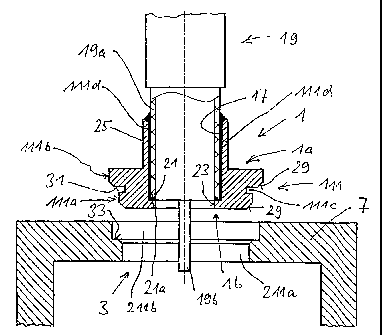
Figure 1 shows a schematic cross section of a coaxial
terminal connection, which comprises, firstly, a plug-
in element 1 and, secondly, a coupling device 3, which
CA 02510037 2005-06-14
WO 2004/057708 - 13 - PCT/EP2003/012102
in the exemplary embodiment shown is in the form of a
two-stage hole in a wall 7, i.e. an electrically
conductive housing wall 7 or a wall 7 forming part of a
housing.
The plug-in element 1 is in this case in the form of a
sleeve and has an actual plug-in insert 111, which
comprises a leading plug-in section llla and a second
plug-in section 111b which lags in the plug-in
direction. The two plug-in sections 111a and lllb are
provided such that they are offset with respect to one
another in the plug-in direction, i.e. in the axial
direction, by the width of an annular groove lllc. The
annular groove 111c in this case has a smaller diameter
than the two outer diameters of the plug-in inserts
llla and lllb.
The illustration shown in figures 1 to 5 shows the fact
that the plug-in element 1 is formed with a sleeve
attachment 111d, which is formed such that it extends
axially, on the side la which is at the rear with
respect to the plug-in direction.
The plug-in element 1 has an inner hole 17, which is at
least slightly larger than the outer diameter of an
outer conductor 19a, from which the insulation has been
stripped, of a coaxial cable 19. The axial length of
the inner hole 17 almost passes through the entire
axial length of the plug-in element 1, except for a
stop shoulder 21 having a hole 23 having a slightly
smaller diameter than the inner hole 17. This stop
shoulder 21 having the annular attachment 21a formed
thereby is thus formed on the end side lb which lies at
the front in the plug-in direction. As a result, the
coaxial cable 19, from which the insulation has been
stripped away down to the outer conductor 19a, can be
inserted into the plug-in element 1 until it stops
against the stop shoulder 21. Before the further
connection to the accommodating opening 3 or else after
CA 02510037 2005-06-14
WO 2004/057708 - 14 - PCT/EP2003/012102
the connection to the coupling device 3 has been
produced, a soldering procedure can then be carried out
in order to effectively electrically conductively
connect the outer conductor 19a to the electrically
conductive plug-in element 1 by means of the solder 25.
The corresponding inner conductor 19b finally passes
through the plug-in element 1 at a suitable length, as
is illustrated, for example, in figure 1. In this case,
it can also be seen from the drawings that the hole 23
is dimensioned such that the inner conductor 19b of the
coaxial cable 19 can be passed through it without any
problems and plugged in, without, in the finally
positioned state of the inner conductor, electrical
contact being made with the plug-in element 3.
As can be seen in figures 2 to 4, the plug-in section
l11a lying at the front in the plug-in direction has a
smaller outer diameter than the second plug-in section
111b which lags in the plug-in direction. The two plug-
in sections are provided on their outer circumference
with a knurl 27, for example an axial knurl or a
transverse knurl etc., whose outer diameter, before the
connection to the coupling device 3, is at least
slightly larger than the corresponding inner diameter
of the coupling device 3 which is yet to be explained
below.
As can be seen in figure 1 with reference to the
exemplary embodiment, the coupling device 3, which is
in this case incorporated in the form of an electrical
housing wall 7, is likewise of two-stage design and has
a first accommodating section 211a having a smaller
diameter and a second accommodating section 211b, which
lies offset with respect thereto in the axial
direction, having a larger diameter. The two diameters
or the two shapes and sizes of the accommodating plug-
in sections 211a and 211b are matched in principle to
the shape and size of the two plug-in sections llla and
111b, which are likewise offset, and differ only in the
CA 02510037 2005-06-14
WO 2004/057708 - 15 - PCT/EP2003/012102
fact that the outer circumference on the plug-in
attachments is slightly larger than the respectively
associated accommodating sections 211a and 211b owing
to the knurl 27 which is introduced at said plug-in
attachments before they are inserted into the
accommodating opening 3 (coupling device). The core
diameters of the plug-in sections provided with a knurl
are, however, smaller than the corresponding inner
diameters of the accommodating opening 3, with the
result that after pressing-in, contact is only made
with the knurl tips, and only low joining forces are
required even in the case of very large dimensions.
Owing to the introduction of the circumferential
annular groove lllc, advantages in terms of
manufacturing result when the knurl 27 formed on the
outer circumference is produced. In the lead direction,
in this case the respective knurl 27 is in each case
provided with a flattened section 29 in order to
prevent chipping during assembly. The surface 31, which
points towards the front in the plug-in direction, of
the plug-in section lllb having larger dimensions in
this case at the same time acts as a stop surface or
stop shoulder 31, which is formed on a corresponding
stop surface or stop shoulder 33 at the transition from
the accommodating section 211a having smaller
dimensions to the accommodating section 211b having
larger dimensions of the-accommodating opening 3.
In order to produce the fixed connection, the plug-in
element 1 is then pressed into the accommodating
opening 3, which is sometimes also referred to as the
coupling element 3, by means of a suitable pressing
tool (which may have smaller dimensions than the
diameter of the plug-in section lllb having larger
dimensions), the outwardly protruding teeth of the
knurls 27 now forming notches in the material of the
housing wall 7. Owing to the sliding movement, possible
oxide layers are destroyed, and a self-cleaning effect
CA 02510037 2005-06-14
WO 2004/057708 - 16 - PCT/EP2003/012102
takes place which ensures optimal contact-making
without electrical faults.
The two-stage contact mechanism ensures that currents
can flow back and forth both from the inner and from
the. outer side of the coaxial cable outer conductor (in
particular if it is located in an electromagnetic
field) in a clearly defined manner to the housing wall
7, that is to say both via the contact region A between
the leading plug-in section llla in interaction with
the accommodating section 211a and also via the further
interaction in the contact region B between the second
plug-in section 111b which is formed such that it lags
in the plug-in direction and the accommodating section
211b.
The in each case uniquely defined electrical contact
zones are identified by A and B in figure 5.
Naturally, a plurality of inner holes 17 may also be
provided on the plug-in element 1 for the purpose of
accommodating coaxial cables.
The exemplary embodiment shown in figure 6 differs from
the previous exemplary embodiment only by the fact that
the wall section 7 is provided with a thicker section
of material 7' in the region of the accommodating
opening 3 compared with the remaining housing or wall
sections 7.
With reference to exemplary embodiment 7, it is merely
shown that the arrangement of the axially offset plug-
in sections llla and ilib and the associated
accommodating sections 211a and 211b of the
accommodating opening 3 may also be formed in the
opposite fashion to that shown in the exemplary
embodiment shown in figures 1 and 5. In the exemplary
embodiment shown in figure 7, the plug-in element 1 is
introduced into the corresponding recess from the inner
CA 02510037 2005-06-14
WO 2004/057708 - 17 - PCT/EP2003/012102
side of the housing. In this case, the soldered
connections between the plug-in element 1 and the
coaxial cable can be produced once the press connection
between the plug-in element 1 and the coupling device 3
has been produced or even beforehand. In this case, the
cable needs to be passed through the coupling opening
211 before pressing-in.
In the exemplary embodiment shown in figure 8, it is
shown that the plug-in element 1 does not need to be in
the form of a sleeve but that the corresponding inner
hole 17 can also be formed transversely with respect to
the axial direction of the plug-in attachments 111a and
111b in a rear section lllf of the plug-in element 1 so
as to form a stop shoulder 21. It is also possible for
knurls to be provided at both ends of the plug-in
element, and for contact to be made with said plug-in
element and, at the same time, two parallel housing
walls.
With reference to figures 10 and 11, it is also shown
that the plug-in element 1 does not necessarily need to
approximate a circular shape in the axial view.
Elliptical shapes, rectangular shapes or generally
n-polygonal or other basic shapes are also conceivable.
In this case, the accommodating sections 211a and 211b
of the coupling device 3 would also have to have a
corresponding shape. In this embodiment too, it is the
case that the circumferential contour or cross-
sectional surface, viewed in the axial or plug-in
direction, or the cross-sectional size of the plug-in
attachment 111a, which leads in the plug-in direction,
is preferably overall smaller than the cross-sectional
sizes of the second plug-in attachment lllb, which lags
in the plug-in direction. Under certain circumstances,
it would also be sufficient, however, for the leading
plug-in section llla to have smaller dimensions than
the lagging plug-in section lllb, at least in a cross-
sectional extent. In addition, the cross-sectional
CA 02510037 2005-06-14
WO 2004/057708 - 18 - PCT/EP2003/012102
shapes of the two plug-in sections may be different,
for example the leading plug-in section may be of
rectangular design, cf. figure 10, whereas the lagging
plug-in section having larger dimensions again has more
of a circular cross-sectional shape, for example.
For reasons of completeness, mention will also be made
of the fact that the mentioned knurls 27 do not
necessarily need to be formed on the outer
circumference of the two plug-in sections, but, quite
the reverse, may also be formed on the inner wall,
interacting therewith, of the two accommodating
sections 211a and 211b or, alternately, on the outer
circumference of one plug-in section and on the inner
surface of a second accommodating section, which is
offset with respect thereto, of the coupling device.
It can also be seen in the drawings that the respective
axial height of the plug-in sections corresponds to the
axial heights of the accommodating sections of the
coupling device. As a result, in each case the limit
surface which leads in the plug-in direction and the
outer limit surface which lags in the plug-in direction
are arranged such that they are aligned with the inner
and outer housing wall sections.