Language selection

Search

Patent 2510281 Summary

Third-party information liability

Some of the information on this Web page has been provided by external sources. The Government of Canada is not responsible for the accuracy, reliability or currency of the information supplied by external sources. Users wishing to rely upon this information should consult directly with the source of the information. Content provided by external sources is not subject to official languages, privacy and accessibility requirements.

Claims and Abstract availability

Any discrepancies in the text and image of the Claims and Abstract are due to differing posting times. Text of the Claims and Abstract are posted:

  • At the time the application is open to public inspection;
  • At the time of issue of the patent (grant).
(12) Patent Application: (11) CA 2510281
(54) English Title: DOWNHOLE STABILIZER
(54) French Title: STABILISATEUR DE FOND DE TROU
Status: Deemed Abandoned and Beyond the Period of Reinstatement - Pending Response to Notice of Disregarded Communication
Bibliographic Data
Abstracts

English Abstract


A stabilizer comprised of a tubular body which has an exterior surface with
selectively positioned indentations. A sleeve is positioned over the tubular
body. The sleeve
has an interior surface in contact with the exterior surface and a plurality
of radial
longitudinally oriented vanes. A plurality of radial apertures extend through
the sleeve. The
sleeve is secured to the body against rotation or axial movement by set
screws. Each of the
set screws extend through one of the apertures of the sleeve to engage on to
the indentation in
the exterior surface of the body.


Claims

Note: Claims are shown in the official language in which they were submitted.

4
What is Claimed is:
1. ~A stabilizer, comprising:
a tubular body having an exterior surface with selectively positioned
indentations;
and
a sleeve positioned over the tubular body, the sleeve having an interior
surface in
contact with the exterior surface, the sleeve having a plurality of radial
vanes, a plurality of
radial apertures extending through the sleeve, the sleeve being secured to the
body against
rotation or axial movement by set screws, each of the set screws extending
through one of the
apertures of the sleeve to engage on to the indentation in the exterior
surface of the body.
2. ~The stabilizer as defined in Claim 1, wherein the selectively positioned
indentions are
positioned at regular intervals.
3.~The stabilizer as defined in Claim 1, the plurality of radial apertures are
positioned on
the radial vanes where the sleeve is thickest.

Description

Note: Descriptions are shown in the official language in which they were submitted.


CA 02510281 2005-06-13
1
TITLE OF THE INVENTION:
Downhole Stabilizer
FIELD OF THE INVENTION
The present invention relates to a stabilizer, that is used to stabilize
tubular bodies
positioned downhole, such as a down hole drilling motor
BACKGROUND OF THE INVENTION
A downhole drilling motor is in excess of 25 feet in length. When drilling
with a
downhole drilling motor, some flexing of the downhole drilling motor occurs
whenever the
drill string becomes differentially stuck down hole, due to uneven fluid
pressure acting upon
the stator housing. This flexing is undesirable, as it causes excessive wear
of the stator. In
order to reduce this flexing and protect the drilling motor, stabilizers are
placed both above
and below the drilling motor. Stabilizers, such as that disclosed in Canadian
application
number 2,439,331 can be effective, but there are inherent limitations on how
small they can
be constructed without adversely effecting threaded connections.
SUMMARY OF THE INVENTION
According to the present invention there is provided a stabilizer comprised of
a
2 0 tubular body which has an exterior surface with selectively positioned
indentations. A sleeve
is positioned over the tubular body. The sleeve has an interior surface in
contact with the
exterior surface and a plurality of radial longitudinally oriented vanes. A
plurality of radial
apertures extend through the sleeve. The sleeve is secured to the body against
rotation or axial
movement by set screws. Each of the set screws extend through one of the
apertures of the
2 5 sleeve to engage on to the indentation in the exterior surface of the
body.
BRIEF DESCRIPTION OF THE DRAWINGS
These and other features of the invention will become more apparent from the
following description in which reference is made to the appended drawings, the
drawings are
3 0 for the purpose of illustration only and are not intended to in any way
limit the scope of the
invention to the particular embodiment or embodiments shown, wherein:
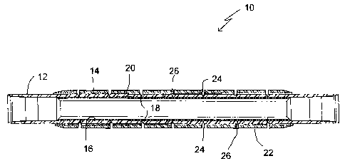
FIG. 1 is a side elevation view, in section, of a stabilizer constructed in
accordance

CA 02510281 2005-06-13
2
with the teachings of the present invention.
FIG. 2 is a side elevation view, in section, of a tubular body of the
stabilizer
illustrated in FIG 1.
FIG. 3 is a side elevation view, in section, of a sleeve of the stabilizer
illustrated in
FIG 1.
FIG. 4 is a end elevation view, in section, of the stabilizer illustrated in
FIG 1.
DETAILED DESCRIPTION OF THE PREFERRED EMBODIMENT
The preferred embodiment, a stabilizer generally identified by reference
numeral 10,
will now be described with reference to FIG. l through 4.
Structure and Relationship of Parts:
Referring to FIG. 1, there is a stabilizer 10 which includes a tubular body 12
and a sleeve 14.
Referring to FIG. 2, tubular body 12 has an exterior surface 16 with
selectively positioned
indentations 18. Referring to FIG. 1, sleeve 14 is positioned over tubular
body 12. Sleeve 14
has an interior surface 20 in contact with exterior surface 16. Referring to
FIG. 4, sleeve 14
has a plurality of radial longitudinally oriented vanes 22. Referring to FIG.
3 and 4, a
plurality of radial apertures 24 extend through sleeve 14. Referring to FIG.
3, radial apertures
24are positioned at regular intervals along sleeve 14. Referring to FIG.1,
sleeve 14 is secured
2 0 to tubular body 12 against rotation or axial movement by set screws 26.
Set screws 26 extend
through apertures 24 of sleeve 14 to engage on to indentation 18 in exterior
surface 16 of
tubular body 12. Plurality of radial apertures 24 are positioned on radial
longitudinally
oriented vanes 22 where the sleeve 14 is thickest.
2 5 Operation:
The use and operation of stabilizer 10 will now be described with reference to
FIG. 1.
Referring to FIG. l, sleeve 14 is positioned over tubular body 12. Set screws
26 are then
threaded through each of apertures 24 of sleeve 14 to engage on to indentation
18 in exterior
surface 16 of tubular body 12 such that sleeve 14 is secured to tubular body
12 against
3 0 rotation or axial movement. As set screws 26 are used to secured sleeve 14
to tubular body
12 rather than threading the parts together, the size of stabilizer is reduced
allowing it to
operate in smaller spaces. Drilling motors can drill different sizes of bore
holes depending

CA 02510281 2005-06-13
3
upon what bit is used. For example, a 4 7/8 inch diameter motor can be used to
form a bore
hole which may vary in size between 6 inches and 6 7/8 inches. Stabilizer 10
can readily be
adapted to suit the bore hole, by having several sizes of sleeve 14 on site
and selecting an
appropriate sized sleeve 14.
Variations:
Stabilizer 10 has been illustrated with one of many possible vane
configurations. The
vanes illustrated are longitudinally oriented in a linear configuration. It
will be appreciated
that they vanes could be longitudinally oriented in a helical configuration.
The vane
configuration is not a critical part of the invention. One skilled in the art
will be able to select
suitable vane configurations.
In this patent document, the word "comprising" is used in its non-limiting
sense to
mean that items following the word are included, but items not specifically
mentioned are not
excluded. A reference to an element by the indefinite article "a" does not
exclude the
possibility that more than one of the element is present, unless the context
clearly requires that
there be one and only one of the elements.
It will be apparent to one skilled in the art that modifications may be made
to the
illustrated embodiment without departing from the spirit and scope of the
invention as
2 0 hereinafter defined in the Claims.

Representative Drawing
A single figure which represents the drawing illustrating the invention.
Administrative Status

2024-08-01:As part of the Next Generation Patents (NGP) transition, the Canadian Patents Database (CPD) now contains a more detailed Event History, which replicates the Event Log of our new back-office solution.

Please note that "Inactive:" events refers to events no longer in use in our new back-office solution.

For a clearer understanding of the status of the application/patent presented on this page, the site Disclaimer , as well as the definitions for Patent , Event History , Maintenance Fee  and Payment History  should be consulted.

Event History

Description Date
Application Not Reinstated by Deadline 2012-01-03
Inactive: Dead - No reply to s.30(2) Rules requisition 2012-01-03
Deemed Abandoned - Failure to Respond to Maintenance Fee Notice 2011-06-13
Inactive: Abandoned - No reply to s.30(2) Rules requisition 2011-01-04
Inactive: S.30(2) Rules - Examiner requisition 2010-07-02
Letter Sent 2010-02-02
Amendment Received - Voluntary Amendment 2010-01-26
Reinstatement Requirements Deemed Compliant for All Abandonment Reasons 2010-01-26
Reinstatement Request Received 2010-01-26
Inactive: Abandoned - No reply to s.30(2) Rules requisition 2009-01-28
Inactive: S.30(2) Rules - Examiner requisition 2008-07-28
Letter Sent 2007-05-11
Request for Examination Requirements Determined Compliant 2007-05-03
All Requirements for Examination Determined Compliant 2007-05-03
Request for Examination Received 2007-05-03
Application Published (Open to Public Inspection) 2006-12-13
Inactive: Cover page published 2006-12-12
Inactive: First IPC assigned 2005-08-19
Inactive: Filing certificate - No RFE (English) 2005-07-28
Application Received - Regular National 2005-07-28

Abandonment History

Abandonment Date Reason Reinstatement Date
2011-06-13
2010-01-26

Maintenance Fee

The last payment was received on 2010-04-13

Note : If the full payment has not been received on or before the date indicated, a further fee may be required which may be one of the following

  • the reinstatement fee;
  • the late payment fee; or
  • additional fee to reverse deemed expiry.

Patent fees are adjusted on the 1st of January every year. The amounts above are the current amounts if received by December 31 of the current year.
Please refer to the CIPO Patent Fees web page to see all current fee amounts.

Fee History

Fee Type Anniversary Year Due Date Paid Date
Application fee - standard 2005-06-13
MF (application, 2nd anniv.) - standard 02 2007-06-13 2007-05-03
Request for examination - standard 2007-05-03
MF (application, 3rd anniv.) - standard 03 2008-06-13 2008-04-04
MF (application, 4th anniv.) - standard 04 2009-06-15 2009-04-14
Reinstatement 2010-01-26
MF (application, 5th anniv.) - standard 05 2010-06-14 2010-04-13
Owners on Record

Note: Records showing the ownership history in alphabetical order.

Current Owners on Record
WILLIAM R. WENZEL
Past Owners on Record
None
Past Owners that do not appear in the "Owners on Record" listing will appear in other documentation within the application.
Documents

To view selected files, please enter reCAPTCHA code :


To view images, click a link in the Document Description column. To download the documents, select one or more checkboxes in the first column and then click the "Download Selected in PDF format (Zip Archive)" or the "Download Selected as Single PDF" button.

List of published and non-published patent-specific documents on the CPD .

If you have any difficulty accessing content, you can call the Client Service Centre at 1-866-997-1936 or send them an e-mail at CIPO Client Service Centre.


Document
Description 
Date
(yyyy-mm-dd) 
Number of pages   Size of Image (KB) 
Description 2010-01-25 3 123
Claims 2010-01-25 1 22
Description 2005-06-12 3 118
Abstract 2005-06-12 1 14
Drawings 2005-06-12 3 36
Claims 2005-06-12 1 19
Representative drawing 2006-11-16 1 10
Drawings 2010-01-25 3 37
Filing Certificate (English) 2005-07-27 1 158
Reminder of maintenance fee due 2007-02-13 1 110
Acknowledgement of Request for Examination 2007-05-10 1 176
Courtesy - Abandonment Letter (R30(2)) 2009-05-05 1 165
Notice of Reinstatement 2010-02-01 1 171
Courtesy - Abandonment Letter (R30(2)) 2011-03-28 1 164
Courtesy - Abandonment Letter (Maintenance Fee) 2011-08-07 1 172
Correspondence 2005-07-27 1 32
Correspondence 2007-02-13 1 39
Fees 2007-05-02 1 30
Correspondence 2007-05-10 1 85
Fees 2008-04-03 1 26
Correspondence 2009-05-05 1 81
Fees 2009-04-13 1 33
Correspondence 2010-02-01 1 71
Fees 2010-04-12 1 29
Correspondence 2011-03-28 1 71
Correspondence 2011-08-07 1 81