Language selection

Search

Patent 2510329 Summary

Third-party information liability

Some of the information on this Web page has been provided by external sources. The Government of Canada is not responsible for the accuracy, reliability or currency of the information supplied by external sources. Users wishing to rely upon this information should consult directly with the source of the information. Content provided by external sources is not subject to official languages, privacy and accessibility requirements.

Claims and Abstract availability

Any discrepancies in the text and image of the Claims and Abstract are due to differing posting times. Text of the Claims and Abstract are posted:

  • At the time the application is open to public inspection;
  • At the time of issue of the patent (grant).
(12) Patent: (11) CA 2510329
(54) English Title: VARIABLE-RATIO TRANSMISSION DEVICE
(54) French Title: DISPOSITIF DE TRANSMISSION A RAPPORT VARIABLE
Status: Deemed expired
Bibliographic Data
(51) International Patent Classification (IPC):
  • F16H 1/32 (2006.01)
  • F16H 3/76 (2006.01)
(72) Inventors :
  • BAUSOLA, GIUSEPPE (Italy)
  • CONTARDO, GIOVANNI (Italy)
(73) Owners :
  • ORBITECH ENGINEERING S.R.L. (Italy)
(71) Applicants :
  • ORBITECH ENGINEERING S.R.L. (Italy)
(74) Agent: BORDEN LADNER GERVAIS LLP
(74) Associate agent:
(45) Issued: 2011-06-21
(86) PCT Filing Date: 2003-12-05
(87) Open to Public Inspection: 2004-07-01
Examination requested: 2008-12-03
Availability of licence: N/A
(25) Language of filing: English

Patent Cooperation Treaty (PCT): Yes
(86) PCT Filing Number: PCT/IT2003/000802
(87) International Publication Number: WO2004/055411
(85) National Entry: 2005-06-15

(30) Application Priority Data:
Application No. Country/Territory Date
PC2002A000038 Italy 2002-12-16

Abstracts

English Abstract


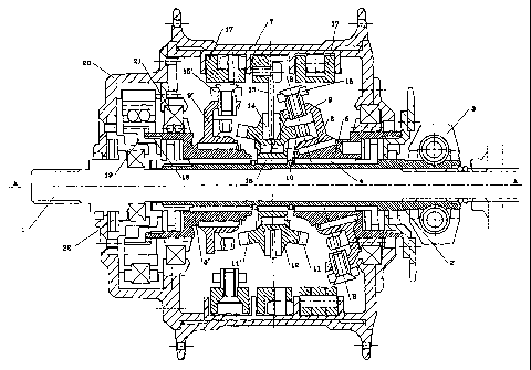
A variable-ratio transmission device is disclosed comprising: a support shaft
(1); an hollow shaft (5) rotatingly assembled onto the shaft (1); a support
(9) assembled onto the hollow shaft (5) in a rotating way with respect to the
shaft around a slanted axis with respect to an axis of the support shaft (1);
a plurality of rollers or teeth (10) arranged in a circular series on the
support (9); a wheel assembled idle onto the shaft (1), equipped with a front
toothing (11) adapted to be engaged by the rollers or teeth (10) assembled on
the support (9); a rotation of the hollow shaft (5) subjecting the support (9)
to an orbital movement adapted to take the teeth or rollers of the support to
engage the toothing of the idle wheel (12); means adapted to establish a
connection between the wheel (12) and a user to which motion is transmitted,
wherein it provides means adapted to axially slide the support (9) or the
wheel (12) with respect to the shaft (1).


French Abstract

La présente invention a trait à un dispositif de transmission à rapport variable comportant : un arbre support (1) ; un arbre creux (5) monté en rotation sur l'arbre (1) ; un support (9) monté sur l'arbre creux (5) en rotation par rapport à l'arbre autour d'un axe incliné par rapport à un axe de l'arbre support (1) ; une pluralité de galets ou de dents (10) disposée en séquence circulaire sur le support (9) ; une roue montée folle sur l'arbre (1), munie d'une denture avant (11) apte à s'engager avec les galets ou dents (10) montés sur le support (9) ; une rotation de l'arbre creux (5) entraînant un mouvement orbital du support (9) apte à provoquer l'engagement des dents ou galets du support avec la denture de la roue folle (12) ; des moyens destinés à établir une connexion entre la roue (12) et un utilisateur auquel le mouvement est transmis, où sont prévus des moyens aptes à entraîner un coulissement axial du support (9) sur la roue (12) par rapport à l'arbre (1).

Claims

Note: Claims are shown in the official language in which they were submitted.


CLAIMS

1. Variable-ratio transmission device characterised in
that it provides at least one support (9) for a circular
series of rollers (10), said support being assembled idle
on a shaft (5) with slanted axis connected to motor means
(6), a rotation of said shaft (5) with slanted axis
making said support (9) perform an orbital movement that
takes it to engage a toothed wheel (12) with front
toothing (11), said toothed wheel (12) with front
toothing (11) being connected to a user, and means (2, 3)
being provided adapted to axially slide said at least one
support (9), in order to change a reduction ratio.
2. Variable-ratio transmission device according to claim
1, characterised in that said toothed wheel (12) with
front toothing (11) has, on an opposite part to said
toothing (11), a second series of teeth or rollers (11')
that engage a series of rollers or respectively teeth
assembled on a support (9') connected to a user, means
(2, 3) being provided adapted to axially slide one or
both of said supports (9, 9') in order to change a
reduction ratio.
3. Variable-ratio transmission device characterised in
that it comprises:
.cndot. a support shaft (1);
.cndot. an hollow shaft (5) rotatingly assembled onto said
support shaft (1);
.cndot. a support (9) assembled onto said hollow shaft (5)
in a rotating way with respect to said hollow shaft
(5) around a slanted axis with respect to an axis of
said support shaft (1);
.cndot. a plurality of rollers or teeth (10) arranged in a
circular series on said support (9);
-8-


.cndot. a wheel assembled idle onto said support shaft (1),
equipped with a front toothing (11) adapted to be
engaged by said rollers or teeth (10) assembled on
said support (9);
.cndot. a rotation of said hollow shaft (5) subjecting said
support (9) to an orbital movement adapted to take
said teeth or rollers (10) of said support (9) to
engage said toothing (11) of said idle wheel (12)
.cndot. means adapted to establish a connection between said
wheel (12) and a user to which motion is
transmitted, characterised in that it provides means
adapted to axially slide said support (9) or said
wheel (12) with respect to said support shaft (1).
4. Transmission device according to claim 3,
characterised in that it provides on said toothed wheel
(12), from an opposite part to said front toothing (11),
a further front toothing (11') that engages the rollers
of a second support (9') assembled with its axis slanted
on an hollow shaft (5') that is also assembled onto said
shaft (1), said second hollow shaft (5') being connected
to a user such as an hub of a velocipede.
5. Transmission device according to claim 4,
characterised in that said second hollow shaft (5) is
connected through a free wheel to an hub box.
6. Transmission device according to claim 5;
characterised in that it provides, on an internal part of
the hub, a pair of free wheels (17, 17') to which a pair
of rings (15, 15') are respectively hinged, in turn
respectively hinged to the supports (9, 9') so that said
rings (15, 15') can rotate with respect to said free
wheels (17, 17') around a first axis and with respect to
said supports (9, 9') around a second axis that is
-9-


orthogonal with the first axis.
7. Transmission device according to claim 6,
characterised in that said hollow shafts (5, 5') are
rotatingly assembled on a grooved hollow shaft (2), in
turn only slidingly assembled onto said support shaft
(1).
8. Transmission device according to any one of claims 2
to 7, characterised in that it provides said wheel (l2)
with double front toothing assembled on a central ring-
shaped support (14), in turn assembled onto a support
that is integral with the wheel hub.
-10-

Description

Note: Descriptions are shown in the official language in which they were submitted.


CA 02510329 2005-06-15
WO 2004/055411 PCT/IT2003/000802
VARIABhE-RATIO TRANSMISSION DEVICE
The present invention refers to the field of motion
transmission kinematisms, particularly for vehicles, and
deals, more particularly, with a variable-ratio
transmission device that operates continuously,
comprising a support with a circular series of teeth or
rollers that rotates around°a slanted axis, in order to
perform an orbital motion, and meshes with a crown with
teeth that are parallel to the axis.
In turn, the crown can directly actuate a user such
as, for example, a velocipede hub or, according to a
preferred embodiment of the invention, from its opposite
part the crown can 'have a second series of teeth that
mesh with a circular series of rollers, in turn assembled
on a support with slanted axis that is able to perform an
orbital movement, said second support being connected to
a user.
The system provides for means adapted to axially
slide said roller supports, in order to continously
change the reduction ratio.
A transmission device is thereby obtained that is
composed of a stepless speed change gear, with a ratio
among speeds that is continuously variable within an
extremely wide range.
As known, it would be highly useful to be able to
have available, in vehicles, a transmission with
continuously changing ratio, both for a more comfortable
and soft driving, and to be able to better exploit the
-1-


CA 02510329 2005-06-15
WO 2004/055411 PCT/IT2003/000802
engine characteristics that, as is well known, provides
an optimum efficiency for a well defined rotation speed.
Different types of transmission are known and
comprise stepless speed change gears, but these are
systems that are excessively encumbrant and cumbersome
and that are adapted only for certain types of vehicles
but cannot be assembled, for example, on velocipedes such
as bicycles, motorcycles or the like.
The present invention belongs to this sector and
proposes a'continuously variable-ratib transmission
devices as claimed in Claim 1, that can find a wide~range
of applications, also due to the fact that its speed can
be'changed within an extremely wide range'and that, due
to its characteristics; is particularly adapted to be
used also as applied to velocipedes, such as bicycles,
motorcycles, or, made of plastics or other light-weight
and sturdy material, to white goods or cutting machines,
or the like.
The arrangement of the device according to the
invention is such as to allow easily inserting it within
an hub of a motorcycle wheel. The description that
follows refers, only as a mere example, to the specific
case of a trarnsmission device for velocipedes such as
bicycles or motorcycles, but it is clear that the same
inventive idea can be validly applied also to different
fields and that the scope is not limited by the specific
case as described, but extends to all pieces of equipment
and vehicles that adopt this transmission device.
The present invention will now be described in
detail, as a non-limiting example, with reference to the
enclosed drawings, in which:
- Figure 1 schematically sectionally shows a first
embodiment of a transmission device according to the
-2-


CA 02510329 2005-06-15
WO 2004/055411 PCT/IT2003/000802
invention;
- Figure 2 schematically sectionally shows a further
preferred embodiment of the transmission device according
to the invention.
With reference to Figure 1, reference 1 points out a
fixed shaft, that can for example be the shaft of the
driving wheel of a velocipede, on which the transmission
device according to the invention is assembled.
The shaft 1 is grooved and an hollow shaft 2 is
assembled thereon and can axially slide with respect to
the shaft 1.
The hollow shaft 2 position can be changed for
example by means of a ring nut 3 or another known system,
for example by means of mechanisms with worm screws, or
with electronic circuit control.
A pair of hollow shafts 5 and 5' are assembled onto
the shaft 2, by interposing bearings, bushings or the
like, referenced with 4.
The shaft 5 is the motion inlet shaft and in case of
a transmission for velocipedes is stiffly connected to a
pinion or a toothed crown 6 that is moved by the chain.
The hollow shaft 5' instead is connected, as will be
described below, to the wheel hub, referenced by number
7.
The external surface of the shaft 5 is worked in
order to define, at least for a certain length, a
cylindrical surface with slanted axis B-B with respect to
axis A-A of the support shaft 1.
In practice, following the rotation of the hollow
shaft 5 around axis A-A, axis B-B of the slanted length
describes a tapered sufrace with its vertex on axis A-A.
On the shaft 5, next to the length with slanted
axis, a support 9 is assembled, by interposing bearings
-3-


CA 02510329 2005-06-15
WO 2004/055411 PCT/IT2003/000802
or bushings 8, such support 9 being substantially
composed of a disk or a wheel that has, perimetrally, a
plurality of teeth or rollers 10 whose axis rests on a
plane that is parallel with the support 9 plane.
The rollers 10 are provided to be engaged with the
toothing 11 of a wheel 12 assembled idle on a support 13
that is integral with the wheel hub 7.
Bearings or bushings 14 allow the wheel 12 to freely
rotate with respect to its own support.
A ring 15 is hinged, through a pair of diametrally
opposite pins 16, to the support 9 of the rollers l0. It
is therefore possible to rotate the ring 15 relative to
the support 9, around a first axis that is substantially
parallel to the plane of said support 9.
In turn, the ring 15 is hinged, through two
diametrally opposite pins that are offset by about 90°
with respect to pins 16, to an external ring 17 that is
part of ,a free-wheeled device that is integral with the
internal surface of the hub 7.
The rings 15 and 17 consequently make a sort of
cardan joint that allows the support 9 of the rollers 10
to rotate with respect to the ring 11 around a first axis
and with respect to the ring 17 around a second axis that
is orthogonal with the previous axis.
In practice, due to these chances of movement around
two orthogonal axes, the support 9 can perform an orbital
movement, taking in succession the rollers 10 to engage
the teeth 11 of the wheel 12.
The number of rollers 10 on the support 9 is
different from the number of teeth 11 of the wheel 12
that are engaged by the rollers 10.
According to a first embodiment of the invention,
the wheel 12 has, from the opposite part to the toothing
-4-


CA 02510329 2005-06-15
WO 2004/055411 PCT/IT2003/000802
1l, a symmetrical toothing 11' that engages a series of
rollers assembled on the disk support 9' symmetrical to
the support 9 and assembled, by interposing bearings, on
a length of the hollow shaft 5' that has a slanted axis.
The shaft 5' engages, thr~ugh a toothing 18, a free
wheel 19 that in turn is assembled on a box 20 secured to
the hub 7.
This latter one is assembled on the shafts 5 and 5'
by interposing bearings 21 that allow the hub to freely
rotate with respect to the shafts.
Like support 9, also support 9' is hinged to a ring
15' in turn hinged, according to an axis that is
orthogonal to the previous one, to a free-wheel device
17', on the internal surface of the hub 7.
Tn case of application of the device to
motorvehicles, the connection between free wheel 19 and
box 20 occurs by interposing one of more clucth disks 22.
The operation is as follows.
Motion from the chain is transmitted to the pinion
6, that in turn rotate the hollow shaft 5.
The consequent rotation of the length with slanted
axis for this shaft imparts to the support 9 an orbital
movement that takes in succession the rollers 10 to mesh
with the teeth 11 of the wheel 12.
The support 9 can also angularly rotate around axis
A-A together with the hollow shaft 5 and these movements,
orbital and angular ones, are independent and can be
algebraically summed.
In practice the support 9 can perform an angular
movement around the axis A-A, in practice rotating around
this axis and always engaging with the same roller the
toothed wheel 12 that is thereby dragged rotating at the
same speed of the shaft 5.


CA 02510329 2005-06-15
WO 2004/055411 PCT/IT2003/000802
The second movement is the orbital one, so that the
support 9 assumes a different rotation speed with respect
to the eccentric of the shaft 5 and therefore starts
"orbiting" by sequentially meshing with the wheel 12,
namely with one tooth after the other, like a traditional
gear.
In this case, with an orbital movement of the
support 9, the wheel 12 is rotated with a reduced angular
speed with respect to the angular speed of the hollow
shaft 5, with a reduction ratio that changes depending on
the ratio between number of support rollers and number of
teeth 11, in addition to the axial position of the
support 5, by changing which it is possible to change the
lever arm length with which the rollers 10 go and mesh
the rollers 10 of the toothed wheel 12, thereby changing
the reduction ratio.
At the beginning of operation, the hub 7 is still
and prevents the rings 17 and 15 from rotating, so that
the support 9 can only perform an orbital movement,
rotating the wheel 12 with a certain reduction ratio.
From the opposite part, the teeth 11' mesh with the
rollers 10' of the support 9'. The free wheel 17'
prevents the assembly from rotating backwards, 'so that
the support 9' is forced to perform an orbital movement
that moves it forward.
This movement is transformed into a rotation~of~the
eccentric 5' that can be exploited in order tn rotate;
through the free wheel 19, the box 20 and with this the
hub'7 integral therewith.
As soon as the hub starts rotating through the'fre~e
wheel l7, it transmits the angular motion~to th:e ring 15
and from here to the support 9 of the roller's ' 10, which
starts rotating around axis A-A, with a rotation motion
-6-


CA 02510329 2005-06-15
WO 2004/055411 PCT/IT2003/000802
that is summed to the orbital motion and that is
transmitted to the wheel 12.
Now, the central wheel 12, with toothings 11 and
11', is rotated with two types of meshing, orbital and
angular ones, as well as the support 9'.
The angular movement is automatically limited by the
number of hub revolutions.
If necessary, like in case of use on a motorvehicle,
clutch disks 22 can be used for disengaging the device
whtn the vehicle is still, thereby obtaining a
transmission device with a ratio that changes
continuously and within a very wide range, with compact
su es and adapted for numerous applications, among which
vehicles and velocipedes.
zn compliance with a second preferred embodiment of
the invention, the transmission device can have a
simplified configuration that can be seen in Figure 2;
that is lacking the second toothing 11', in addition to
the' second support 9' and the kinematisms downstream of
this one.
~Tri this embodiment, particularly suitable~~~~for
bicycles, the central wheel 12 is directly'COrinected to
the hub 7, that is dragged moving at the beginning only
due to the orbital motion of the support 9, to which it
is overlapped and then, little by little, is replaced by
the angular~motion. ' ~~
A skilled person in the art will then be'~able to
provide numerous modifications and variations,~that will
however have to be deemed all included within the scope
of the present invention as claimed in the following
Claims.

Representative Drawing
A single figure which represents the drawing illustrating the invention.
Administrative Status

For a clearer understanding of the status of the application/patent presented on this page, the site Disclaimer , as well as the definitions for Patent , Administrative Status , Maintenance Fee  and Payment History  should be consulted.

Administrative Status

Title Date
Forecasted Issue Date 2011-06-21
(86) PCT Filing Date 2003-12-05
(87) PCT Publication Date 2004-07-01
(85) National Entry 2005-06-15
Examination Requested 2008-12-03
(45) Issued 2011-06-21
Deemed Expired 2015-12-07

Abandonment History

There is no abandonment history.

Payment History

Fee Type Anniversary Year Due Date Amount Paid Paid Date
Registration of a document - section 124 $100.00 2005-06-15
Application Fee $400.00 2005-06-15
Maintenance Fee - Application - New Act 2 2005-12-05 $100.00 2005-09-19
Maintenance Fee - Application - New Act 3 2006-12-05 $50.00 2006-10-03
Maintenance Fee - Application - New Act 4 2007-12-05 $50.00 2007-10-01
Maintenance Fee - Application - New Act 5 2008-12-05 $200.00 2008-09-30
Request for Examination $800.00 2008-12-03
Maintenance Fee - Application - New Act 6 2009-12-07 $200.00 2009-10-02
Maintenance Fee - Application - New Act 7 2010-12-06 $200.00 2010-08-27
Final Fee $300.00 2011-04-11
Maintenance Fee - Patent - New Act 8 2011-12-05 $200.00 2011-10-03
Maintenance Fee - Patent - New Act 9 2012-12-05 $200.00 2012-10-31
Maintenance Fee - Patent - New Act 10 2013-12-05 $125.00 2013-11-18
Owners on Record

Note: Records showing the ownership history in alphabetical order.

Current Owners on Record
ORBITECH ENGINEERING S.R.L.
Past Owners on Record
BAUSOLA, GIUSEPPE
CONTARDO, GIOVANNI
Past Owners that do not appear in the "Owners on Record" listing will appear in other documentation within the application.
Documents

To view selected files, please enter reCAPTCHA code :


To view images, click a link in the Document Description column. To download the documents, select one or more checkboxes in the first column and then click the "Download Selected in PDF format (Zip Archive)" or the "Download Selected as Single PDF" button.

List of published and non-published patent-specific documents on the CPD .

If you have any difficulty accessing content, you can call the Client Service Centre at 1-866-997-1936 or send them an e-mail at CIPO Client Service Centre.


Document
Description 
Date
(yyyy-mm-dd) 
Number of pages   Size of Image (KB) 
Abstract 2005-06-15 1 78
Claims 2005-06-15 3 103
Drawings 2005-06-15 2 97
Description 2005-06-15 7 303
Representative Drawing 2005-06-15 1 51
Cover Page 2005-09-14 1 65
Representative Drawing 2011-05-26 1 37
Cover Page 2011-05-26 2 77
Correspondence 2005-09-28 1 26
PCT 2005-06-15 3 117
Assignment 2005-06-15 7 253
Correspondence 2011-04-11 1 31
Prosecution-Amendment 2008-12-03 1 31