Note: Descriptions are shown in the official language in which they were submitted.
CA 02511611 2005-06-22
WO 2004/059229 PCT/GB2003/005525
OVEN
The present invention relates to an oven. In particular the present invention
relates to a
development of the type of oven described in the applicants International
patent
application published as WO 01/98092 A1, the content of which is hereby
incorporated
by reference in its entirety.
There is an increasing requirement to recycle materials such as aluminium,
magnesium
and other metals and non-metals. Often such materials will be coated in paint,
oil, water,
to lacquers, plastics, or other volatile organic compounds (V.O.C.s) which
must be removed
prior to re-melting the materials. For materials which are capable of being
processed at
relatively high temperatures without melting, such impurities are typically
removed using
a thermal process which is sometimes lcnown as de-coating. Such thermal de-
coating
processes can also be used to dry and/or sterilize materials prior to
remelting.
For example, aluminium is often used in the production of beverage cans which
are
typically coated in paint, lacquers and/or other V.O.C.s. Before used beverage
cans
(U.B.C.s) or scrap material produced during the manufacture of beverage cans
can be
melted down for recycling, any coatings or other impurities must be removed in
order to
2o minimize metal loss.
Thermal de-coating, however, is not limited to application to aluminium but
can be used
to clean or purify any metal or non-metallic materials which are capable of
withstanding
the temperatures present in the thermal de-coating process. Thermal de-coating
can be
used to de-coat or purify magnesium or magnesium alloys for example.
Known thermal de-coating processes involve exposing the material to be treated
to hot
gases in order to oxidise the coatings and/or impurities which are to be
removed. This
exposure takes place in a closed and controlled environment in which the
temperature and
oxygen content of the hot gases can be controlled during the de-coating
process.
Temperatures in excess of 300 C are required to remove most organic compounds
and an
oxygen level in the range of 6% to 12% is normally required.
CA 02511611 2005-06-22
WO 2004/059229 PCT/GB2003/005525
2
If the temperature and oxygen levels of the hot gases are not carefully
controlled this can
lead to oxidation of the metal as the V.O.C.s which are released during the
thermal
stripping are combusted. This can result in an uncontrolled increase in the
temperature of
the hot gases which leads to further metal loses and can be very dangerous.
The material will usually be shredded before treatment and it is important for
effective
de-coating that all the surfaces of the shredded material are exposed to the
hot gases. If
this does not occur then the treatment becomes less effective and, in the case
of U.B.C.s
in particular, a black stain may be left on the surface of the treated
material. It is also
to desirable for the material to be agitated during the treatment to
physically remove lose
coatings or impurities from the material.
At present there are three main systems which are used on an industrial scale
for thermal
de-coating, these are:
1. STATIC OVEN
In a static oven, the material is staclced on a wire mesh and hot gases are
recirculated
through the oven to heat the material to the required process temperature.
This arrangement is not efficient because the hot gases do not come in to
contact with the
materials that are enclosed witlun the stack of materials on the mesh. As
discussed
previously, it is important in de-coating that all the surfaces of the
materials being treated
are exposed to the hot gases. Also there is no agitation of the material being
treated.
2. CONVEYING OVEN
This system uses a mesh belt conveyor to transport materials for treatment
through an
oven. Hot gasses are passed through the material on the belt as it passes
through the oven.
3o The problems with this method are as follows:
The depth of materials on the belt limits the process. The materials are
CA 02511611 2005-06-22
WO 2004/059229 PCT/GB2003/005525
3
stacked, causing similar problems to those found with the static oven in which
materials at the centre of the stack do not come into contact with the hot
gases
There is no agitation of the materials, so loose coatings are not removed.
The conveyor belt life is short.
The materials have to be constantly fed.
l0 The process is not suitable for low volume or continuously changing
product.
3. ROTATING KILN
A large lciln is inclined to the horizontal so that material fed or charged
into the l~iln at its
highest end travels towards the lowest end, where it is discharged, under the
influence of
gravity. The lciln is rotated so that material within the lciln is agitated
and a flow of hot
gases is provided to heat up the material as it travels through the kiln. A
number of
problems are associated with this method:
2o The material has to be constantly fed.
The process is not suitable for low volume or continuously changing product.
The continuous process requires air loclcs at both ends, materials charge end
and.materials discharge end.
The kiln requires a rotating seal leading to a high level of maintenance.
WO 01/98092 Al describes a pivotable or tiltable oven that overcomes many of
the
3o disadvantages of the previously known apparatus and methods for thermal de-
coating.
For a detailed description of the construction and operation of the oven, the
reader should
refer to WO 01/98092 A1. However, briefly, the oven has a charging portion for
". FEB. 2005 17:05 MARKS & CLERK . ND. 1544 FGB0305525
17-02-2005 002 l~.oz.2c"., 1,.~~=«
p019B7W0 2oD502i6 AmndedSgex
receiving material to be treated and a changeover portion. IrtcorpoAated
within the
changeover portion is a heat treatment chamber through-which a stream or flow
of hot
gasses can be passed. The oven is pivotally moveable between a ~zst position
in which
the changeover portion is higher tbam the charging portion and a second
position in which
s the eltargit~g portion is higher than tha changeover portion Tht arrangement
is such that
the oven can be repeatedly moved between the first and second positions so
that material
within the oven falls fronn one portion to the other portion, passing through
the stream of
hot gasses in the beat treatment chamber. A method of using the apparatus is
also
disclosed.
~o
The above known oven ltas 13~e advantage that it can be used to treat
comparatively tow
volumes of material in a batch process. A further advantage is that by
controlling the
mQVement of the oven, the material lyeing treated can be brought into and out
of the heat
treatment chamber at will, enabling the oven to be operated safely without the
process
t s going autothermic in atr uncontrolled manner and allowing a very fine
degree of control
of the treatment process.
'Z'he oven described in 'WO Q1I98092 A1 has beerA found to work well,
prorriding a
commercially and technically acceptable means of thezmally de-coating
relatively low
Zo volumes of rmarerials. Hourever, when treating Light weight materials, such
as powders or
maroerials that have been shredded into very smiall pieces, there can be a
tendency for
some of the ma6erial being treated to become enh~ainad in the flow of tot
gasses passing
through the heat treatment chamber. Whilst some of the entrained material can
be filtered
our of the gas flow and recollected, there is an overate reduction in the
efficiency of the
zs process.
It is an object of tl~e present irtvencion is to provide an improved oven in
which the
problems of the known oven are overcome or at least reduced.
3o In accordance with the invetltion, there is provided an oven comprising]
a charging portion for receiving material to be fxeated;
a rotatabla changeovex portion comprising an outer chamber and an rioter
trestxnent
CA 02511611 2005-06-22 AMENDED SHEET
m FEB, 2005 17:01 MARKS & CLERK , 003 ~ i~~o2.2o~c GB0305525
17-02-2005 CA 02511611 2005-06-22
P01487W0 2905216 Antet~d~c
Chamber within the outer Chamber,
and means to heat the inner treatrncnt chamber externahy thereof;
the oxen being moveable betweon a fast position in which the changeover
portion is
generally higher than the charging portion and a second position in which the
charging poztion is generally higher than the changeover partaon;
the: inner treatment chamber being adapted to receive mamrial ~Cz~om ttte
charging
portion as the oven rnovea from the fast position to the second position.
It is an advantage of an oven in accordance with the invention, that the
material fitted in
v Q the inner treatment chamber can be heated indirectly by virtue of the
external Iaeatiug of
the inner treatment chamber. A further advantage of an oven in accordance with
the
invention is that the w$Ils of the ixlner ireatrnent chamber axe heated by the
external
heating means. When the material being treated enters the inner treatment
chamber, some
wih come into contact with the hat walls, helping to heat the material and so
reduczng
t5 pxocessirlg times.
In a preferred embodirxlent, the external heating means comnprises a flow of
hot gasses
through the outer treatment chamber and which passes over at least part of the
external
surface of the inner treatment chamber.
It is a particular advantage of the invention that the material being treated
is separated
from the flow of gasses through the outer chamber by the itnter treatment
chamber. As a
result, the material does nit become entrained in the flow of gasses through
the outer
Chamber.
In a particularly preferred embodiment the oven further con'tprises an inlet
means for
AMENDED SHEET
CA 02511611 2005-06-22
WO 2004/059229 PCT/GB2003/005525
6
introducing a flow of hot gases into the inner treatment chamber and outlet
means through
which the flow of hot gasses can exit the inner treatment chamber.
In an oven in accordance with the preferred embodiment a flow or stream of hot
gases can
be generated through the inner treatment chamber. Material entering the inner
treatment
chamber will be introduced into the flow of hot gases in the inner treatment
chamber to be
heated in much the same way as with the prior art oven described in WO
01/98092 Al.
However, because the inner treatment chamber can also be heated externally,
the flow of
hot gasses through the inner treatment chamber can be reduced when treating
lightweight
to materials, so reducing the likelihood of the material becoming entrained.
When treating
heavier materials, the flow of hot gases through the inner treatment chamber
can be
increased to ensure effective treatment. The balance of the flow of hot gases
through the
inner treatment chamber and the external heating of the chamber can be
adjusted to suit
any particular material to the treated.
Preferably, the means for introducing a flow of hot gases comprises an array
of inlet
nozzles.
Advantageously, the array of nozzles are located adj acent a first side wall
of the imier
treatment chamber.
Preferably, the means for introducing a flow of hot gases through the inner
treatment
chamber fiuther comprises an outlet vent through which the gasses can exit the
inner
treatment chamber. The outlet vent may be located in a second side wall of the
inner
treatment chamber opposite from the first wall. Preferably, the outlet vent is
positioned
such that , in use, as the oven moves between the first and second positions,
the material
passing between the charging box and the inner treatment chamber does not fall
through
the outlet vent.
3o Preferably, the oven is rotated in a first direction as it moves from the
first position to the
second position and is rotated in the opposite direction as it moves from the
second
position to the first position.
CA 02511611 2005-06-22
WO 2004/059229 PCT/GB2003/005525
7
Preferably, the oven further comprises a control means for regulating the flow
and/or the
oxygen content of gasses passing through the outer treatment chamber. In which
case, the
control means may also adapted to regulate the flow and/or oxygen level of the
gasses
flowing through the inner treatment chamber independently of the gases flowing
through
the outer treatment chamber.
An embodiment of the invention will now be described, by way of example only,
with
reference to the following drawings in wluch:
to Figure 1 is a front elevation of an oven in accordance with the invention;
Figure 2 is an end elevation of the oven of Figure 1, shown in a first
position;
Figure 3 is a view similax to that of Figure 2 but showing the oven in a
second, inverted
position;
Figure 4 is a perspective view of the oven of Figure 1, showing various
features in hidden
detail;
2o Figure 5 is a perspective view of an inner treatment chamber forming paxt
of the oven of
Figures 1 to 4, shown connected to a charging box of the oven; and
Figure 6 is a schematic diagram showing an oven in accordance with the
invention
connected with a second afterburner and an air pollution control unit.
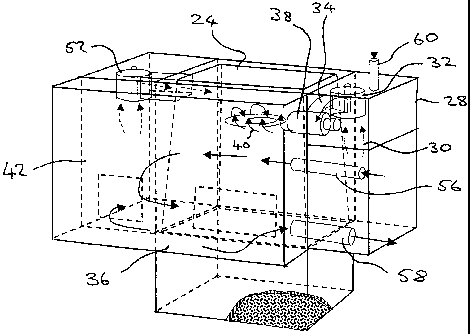
An oven 10 comprises a charging portion 12 and a changeover portion 14. The
oven is
mounted to a support 16 so as to be movable between a first position in which
the
changeover portion is generally higher than the charging portion (as shown in
Figure 2),
and a second position in which the charging portion is generally higher than
the
3o changeover portion (as shown in Figure 3).
The charging portion 12 is in the form of a charging box which is removably
mountable
CA 02511611 2005-06-22
WO 2004/059229 PCT/GB2003/005525
8
to the changeover portion 14. The charging box 12 is substantially rectangular
in shape.
The end of the box which is uppermost when the oven is in the first position
has an
opening 18 through which material can enter and exit the box 12.
The changeover portion 14 has an outer treatment chamber 20 and an inner
treatment
chamber 22 located within the outer treatment chamber. The inner treatment
chamber is
generally rectangular in shape though tapering inwardly towards a base 24. The
inner
treatment chamber 22 has an opening 26 in a face opposite to the base 24,
which face is
lowermost when the oven is in the first position. The opening 26 of the inner
treatment
to chamber is substantially the same size as the opening 18 of the charging
box l2.When the
charging box 12 is mounted to the changeover portion 14, the openings 18, 26
of the
charging box and the inner treatment chamber are aligned face to face so that
material can
pass between the charging box 12 and the imier treatment chamber 22 as the
oven is
moved between the first and second positions.
The oven has means for recirculating a flow of hot gases, which may be a
mixture of air
and volatiles, through the inner and outer treatment chambers 22, 20 in a
maimer similar
to that described in WO 01/98092 Al, to which the reader should refer for a
detailed
description. To this end, as can be seen from Figure 4 in particular, on one
side of the
oven there is a recirculation chamber 28 into which the recirculated gases 30
are drawn
from the outer treatment chamber 20 by a recirculating fan 32. An air mixing
jacket 34
guides the gases from the recirculation chamber 28 into an afterburner chamber
36 in
which the gasses are heated by a burner 38. The walls of the afterburner
chamber 36 can
be air cooled stainless steel walls or may be lined with a suitable refractory
material.
The burner 38 which heats the gasses may be designed to run on either a
gaseous or a
liquid fuel or both. In a preferred embodiment the burner is also designed so
as to be able
to burn the V.O.C.s which axe thermally stripped from the materials in the
inner treatment
chamber 22. These V.O.C.s are drawn out of the inner treatment chamber 22 and
the
outer treatment chamber 20 with the gases 30 by the recirculating fan 32 and
are mixed
with the gases in the mixing jacket 34. The air mixing jacket 34 is designed
to ensure that
the gasses enter the afterburner with a helical flow, as indicated by the
arrows 40, which
CA 02511611 2005-06-22
WO 2004/059229 PCT/GB2003/005525
9
ensures that V.O.C.s have a maximum residence time and exposure to the hot
zone of the
burner flame.
By burning the V.O.C.s the overall thermal efficiency of the oven is increased
since less
fuel need be supplied to heat the gases 30 to the required operating
temperature. If
sufficient V.O.C.s are present, no additional fuel need be added to heat the
gases to the
required temperature so that the process can operate autothermically but in a
controlled
manner.
l0 Burning the V.O.C.s also improves the control of emissions by removing
these pollutants
from the re-circulating gases and reducing the need for further and expensive
treatment of
gases which are exhausted from the afterburner chamber as is described in WO
01/98092
A1.
From the afterburner chamber 36, the hot gases enter a pre-treatment chamber
42 from
where they are feed into the outer treatment chamber 20 on the opposite side
of the oven
from the recirculation chamber 28. As the gases pass through the outer
treatment chamber
from the pre-treatment chamber 42 to the recirculation chamber 28, they flow
around
most of the outer surfaces of the walls of inner treatment chamber. The walls
of the inner
2o treatment chamber are made of a suitable material, such as stainless steel,
and are heated
by the hot gases passing over them. A certain amount of this heat is also
conducted
through the walls into the air within the inner treatment chamber.
In order to provide a flow of hot gases through the inner treatment chamber
22, the inner
treatment chamber 22 is provided with an axray of gas inlet nozzles 44
(indicated
schematically in Figure 5). The nozzles may be located adjacent to a first
side wall 46 of
the inner treatment chamber 22. An opening or outlet vent 48 is provided in a
second side
wall 50 of the imier treaixnent chamber opposite from the first. A further
recirculating fan
52 draws gases from the pre-treatment chamber 42 and supplies the gases to the
nozzles
44 from where they flow across the inner treatment chamber 22 and are drawxn
out
through the outlet vent 48. The gases exiting the outlet vent join with the
gasses flowing
through the outer treatment chamber 20 and are drawn into the recirculating
chamber 28
CA 02511611 2005-06-22
WO 2004/059229 PCT/GB2003/005525
by the first recirculating fan 32. If required, more than one recirculating
fan 52 can be
provided.
A further set of inlet nozzles (not shown) can be provided between the first
and second
5 side walls 46, 50 of the inner chamber if required.
A control system (indicated schematically at 54 in Figure 2) monitors and
controls the
level of oxygen and the temperature of the gases individually in both the
outer treatment
chamber 20 and the inner treatment chamber 22 to ensure the system operates
within safe
l0 and effective limits for thermal de-coating of the material being treated.
Typically, the
oxygen level will be maintained below 16% whilst temperatures in excess of 300
C are
required to remove most organic compounds. A lance 56, regulated by the
control system,
supplies fresh air into the afterburner chamber 36 so as to control both the
required level
of oxygen and temperature of the gases. The afterburner chamber 36 exhausts
combustion
gases through an exhaust pipe 58. The flow of exhaust gases being controlled
via
temperature and pressure controlled damper (not showm).
An auxiliary fresh air inlet 60 is also provided in the recirculation chamber
28. The
auxiliary inlet 60 allows air to enter the recirculation chamber to mix with
the hot gases
and to cool the fan 32. The control system monitors the temperature of the fan
and
operates a valve to control the flow of air through the auxiliary inlet to
maintain the
temperature of the fan below its maximum permitted operating temperature. The
control
system balances the flow of air through the lance 56 and the auxiliary inlet
60 in order to
maintain the required oxygen content and temperature of the gases in the inner
22 and
outer 20 treatment chambers.
The oven 10 is pivotably mounted to the support structure 16. Means 62 are
provided for
automatically moving the oven between the first and second positions under the
control of
the control system 54 for the oven. This means can be of any suitable form and
may, for
3o example, comprise one or more electric or hydraulic motors. The motors may
act through
a gearbox if required. Alternatively the means may comprise one or more
hydraulic or
pneumatic rams. The means could also comprise a combination of motors and
rams.
CA 02511611 2005-06-22
WO 2004/059229 PCT/GB2003/005525
11
The oven is arranged to rotate in the direction indicated by arrow A in Figure
2 when
moving from the first position to the second position. When the oven 10
reaches the
second position, rotation is stoped. To move the ovenl0 from the second
position to the
first position, the oven is rotated in the opposite direction.
As the oven 10 moves from the first position towards the second position, the
first side
wall 46 of the inner treatment chamber 22 remains below the opposing second
side wall
50 in which the outlet vent 48 is provided. Similarly when the oven moves in
the reverse
to direction from the second position to the first position, the wall 46 of
the inner treatment
chamber will again remain below the opposing wall 50 in which the outlet vent
48 is
provided. As the oven is moved from the first position to the second position,
the material
being treated will tend to fall from the charging box 12 onto the first side
wall 46 of the
inner treatment chamber and then downwards on to the base 24 of the inner
treatment
chamber. Similarly when the oven is moved in the reverse direction from the
second
position to the first position the material will tend to fall from the base 24
of the inner
treatment chamber onto the first side wall 46 and then back into the charging
box 12. By
positioning the outlet vent 48 in the wall 50 opposite to the wall 46 which
remains
lowermost during the rotary movement of the oven, it can be ensured that none
of the
material will fall through the outlet vent as the oven moves between the first
and second
positions.
In an alternative embodiment, rather than the oven being rotated reciprocally
between the
first and second positions, the oven could be adapted so that it is rotated
through 360
degrees in the same direction to move from the first position through the
second position
and baclc to the first position. In this alternative arrangement, the outlet
vent 48 in the
inner chamber can be provided with a suitably sized mesh to prevent the
material being
treated from passing through the vent. This arrangement would be most suited
for use in
treating materials having a relatively large size and which can be retained in
the inner
3o treatment chamber 22 by the mesh.
Operation of the oven will now be described.
CA 02511611 2005-06-22
WO 2004/059229 PCT/GB2003/005525
12
The material to be processed is loaded into the charging box 12 which is then
transported
to the oven by means of a fork lift truck or other means. Once the charging
box 12 is in
position it is locked to the changeover portion. The treatment process can
then be initiated
under the control of the control system 54.
The gases passing through the inner 22 and outer 20 chambers of the changeover
portion
are heated. The oven is then rotated from the first position as shown in
Figure 2 until it
reaches the second position shown in Figure 3 in which the oven is inverted.
to
As the oven is rotated, the materials in the charging box 12 will fall under
the influence of
gravity into the inner treatment chamber 22. As they do so, the materials
enter the stream
of hot gases in the inner treatment chamber 22. Also, some of the material
will come into
direct contact with the wall 46 and base 24 of the inner treatment chamber 22
which will
be at an elevated temperature. This heat will be conducted in to the material
to assist in
the heat treatment.
The rotary movement of the oven can then be reversed, until the oven is
returned to the
first position. During this reverse rotary movement, the materials will fall
from the inner
treatment chamber 22 back into the charging box 12. The reciprocal rotary
movement of
the oven between the first and second positions is repeated a number of times
as required
by the process control until the material is fully treated.
As the oven is repeatedly moved between the first and second positions, the
materials
being treated are mixed so that at some point most of the material will have
come into
contact with the heated walls and base 24 of the inner treatment chamber 22.
This helps to
speed up the treatment process by increasing the temperature of the materials.
The treatment process goes through a number of phases or cycles: a heating
cycle during
3o which the hot gases and the materials are brought up to the required
treatment
temperature, a treatment cycle in which the temperature of the gasses and
materials is
maintained at the treatment temperature, and finally a cooling cycle during
which the
CA 02511611 2005-06-22
WO 2004/059229 PCT/GB2003/005525
13
temperature of the gases and the treated material is brought down to a level
at which the
material can be safely removed.
Once the treatment process is completed, the oven is returned to the first
position and the
charging box 12 removed so that the treated material can be transported for
cooling,
storage or further processing as required.
The rotary motion of the oven ensures that the material to be treated passes
through the
stream of gases in the inner treatment chamber 22 in a controlled manner. The
falling
to action of the material also ensures that all the surfaces of the material
become fully
exposed to the gases in the inner chamber 22 promoting an efficient and
effective de-
coating and/or decontamination.
The control system controls the speed and frequency of the rotary movement of
the oven
along with the temperature and oxygen level of the gases in the inner and
outer treatment
chambers 20, 22 in order to oxidize coatings or impurities on the material
whilst ensuring
the process is caiTied out safely and efficiently with minimum loss of the
material being
treated.
2o Any V.O.C.s or other volatiles given off during the treatment of the
material axe removed
from the inner treatment chamber 22 with the gasses as they flow out of the
outlet 48 and
rejoin the gases 30 flowing through the outer treatment chamber to be
recirculated
through the afterburner chamber 36 where most of the V.O.C.s are incinerated.
When a light-weight material is to be treated, the flow of gases through the
inner
treatment chamber 22 can be reduced to the minimum necessary to remove the
volatiles
thermally without entraining the material in the gas flow. To ensure the
material is
brought to a high enough temperature to be successfully de-coated or otherwise
treated,
the flow of gases through the outer treatment chamber 20 around the inner
treatment
3o chamber 22 can be increased and/or the temperature of those gases
increased.
When the material to be treated is relatively heavy, the flow of gases trough
the inner
CA 02511611 2005-06-22
WO 2004/059229 PCT/GB2003/005525
14
treatment chamber 22 can be increased and the flow of gases through the outer
treatment
chamber 20 decreased to the point where most of the heating of the material is
effected by
the gasses flowing through the inner treatment chamber and directly impinging
on the
heavy coated material.
The control means can be set to regulate the flow and temperature of the gases
through
the Timer and outer treatment chambers independently as required for any
particular
material.
l0 The oven may also be provided with a second afterburner and cooling system
as shown
schematically in Figure 6, if required. The second afterburner system 64 can
be located
next to the rotating oven 10 and is connected via ducts 66, which may be
stainless steel
and/or insulated, that transfer some of the hot gases with the volatiles 67
from the inner
treatment chamber 22 into the second afterburner 64.
Inside the second afterburner 64 the volatiles are incinerated with the aid of
a second
burner 68. The exhaust gasses from the second afterburner 64 are cooled in a
separate
cooling system 70 which may be located adjacent the second afterburner system
64. After
passing through the cooling unit 70, the exhaust gasses, which now contain no
fuel or
oxygen and so are inert, can be recirculated baclc into the first afterburner
chamber 36
and/or the second afterburner 64 via further ducts 74 in order to help reduce
the
combustion process further. The hot gasses are circulated through the second
afterburner
64 and the cooling system 70 by a second recirculating fan 76. The cooling
system 70
uses indirect cooling, for example a heat exchanger system, to provided a
controlled .
cooling which yields a temperature level that is acceptable to the air
pollution control unit
72.
A separate stream of exhaust gasses from the oven is taken via another series
of ducts 78,
which may be stainless steel and/or insulated, directly to an air pollution
control unit 72
3o such as a bag or reverse jet filtration system. Preferably, the air
pollution control unit
comprises high temperature ceramic filters that are capable of receiving
gasses having a
temperature greater than 120 degrees Celsius and preferably gasses having a
temperature
CA 02511611 2005-06-22
WO 2004/059229 PCT/GB2003/005525
above 300 degrees Celsius. This means that the gasses do not require dilution
with air
before entering the air pollution control unit and prevents reformation of
dioxins. The
gasses leaving the air pollution control unit into the atmosphere can be
subject to rapid
gas quenching in a known manner.
5
Where the second afterburner and cooling system are not required, they can
simply be
omitted, in which case all the exhaust gasses from the first afterburner
chamber can be
directed to the air pollution control unit 72.
to Whereas the invention has been described in relation to what is presently
considered to be
the most practical and preferred embodiment, it is to be understood that the
invention is
not limited to the disclosed arrangements but rather is intended to cover
various
modifications and equivalent constructions included within the scope of the
invention as
defined by the claims. For example, whilst it is preferred that the external
heating of the
15 inner treatment chamber is effected by means of recirculating hot gasses
through of the
outer treatment chamber, this need not be the case and other suitable means of
externally
heating the imler chamber may be used. In one example, the inner chamber could
be
heated by means of external electrical heating elements. The oven in
accordance with the
invention could also be provided with means for separating the inner treatment
chamber
22 from the charging portion 12 so that the material being treated can be
retained in the
inner chamber 22 or the charging box 12 as the oven is rotated. A suitable
means for
separating the inner treatment chamber 22 may be a series of flaps or dampers
similar to
those described with reference to Figure 5 in WO 01/98092 A2 positioned to
close the
opening 26 of the inner treatment chamber or the opening 18 of the charging
box to
control movement of the material between the charging portion and the inner
treatment
chamber.