Language selection

Search

Patent 2512042 Summary

Third-party information liability

Some of the information on this Web page has been provided by external sources. The Government of Canada is not responsible for the accuracy, reliability or currency of the information supplied by external sources. Users wishing to rely upon this information should consult directly with the source of the information. Content provided by external sources is not subject to official languages, privacy and accessibility requirements.

Claims and Abstract availability

Any discrepancies in the text and image of the Claims and Abstract are due to differing posting times. Text of the Claims and Abstract are posted:

  • At the time the application is open to public inspection;
  • At the time of issue of the patent (grant).
(12) Patent: (11) CA 2512042
(54) English Title: A SCREW WITH A DOUBLE THREAD AND A RECESS IN THE SIDE OF THE SHANK
(54) French Title: VIS A FILET DOUBLE ET ENCOCHE DANS LE COTE DE LA TIGE
Status: Expired and beyond the Period of Reversal
Bibliographic Data
(51) International Patent Classification (IPC):
  • F16B 25/02 (2006.01)
  • F16B 35/04 (2006.01)
(72) Inventors :
  • BUHL, MORTEN FRIIS (Denmark)
(73) Owners :
  • ITW CONSTRUCTION PRODUCTS APS
(71) Applicants :
  • ITW CONSTRUCTION PRODUCTS APS (Denmark)
(74) Agent: FINLAYSON & SINGLEHURST
(74) Associate agent:
(45) Issued: 2009-04-07
(22) Filed Date: 2005-07-14
(41) Open to Public Inspection: 2007-01-14
Examination requested: 2005-07-14
Availability of licence: N/A
Dedicated to the Public: N/A
(25) Language of filing: English

Patent Cooperation Treaty (PCT): No

(30) Application Priority Data: None

Abstracts

English Abstract


A screw (1, 2) includes two recesses (5, 6) in the side of the shank, said
recesses being
arranged diametrically opposite one another, where each recess is shaped as
two
plane segments extending substantially parallel to the axis of the screw and
along a
portion of the shank length.


Claims

Note: Claims are shown in the official language in which they were submitted.

4
WHAT IS CLAIMED IS:
1. A screw comprising:
a double thread; and
two recesses arranged diametrically opposite one another on a radial side
portion of a
shank of the screw, each of the two recesses being shaped as two plane
segments extending
substantially parallel to an axis of the screw and along a portion of the
shank and located so
that a portion of the double thread in which the recesses are formed divides
the remainder of
the double thread into first and second uninterrupted portions one of which
extends from the
recess to a tip of the screw.
2. The screw according to claim 1, wherein a depth of each of the said two
recesses is
approximately 0.15 mm to approximately 0.5 mm taken along a core diameter the
screw shank.
3. The screw according to claim 1, wherein each of the said two recesses
extend along the
screw shank to a location which is approximately 6.0 mm to approximately 14.0
from the tip
of the screw.
4. The screw according to claim 2, wherein each of the said two recesses
extend along the
screw shank to a location which is approximately 6.0 mm to approximately 14.0
from the tip
of the screw.
5. The screw according to claim 1, wherein the screw has a tapered shank
portion and a
non-tapered shank portion, the tapered shank portion extending from the tip of
the screw to the
non-tapered shank portion, and wherein the two recesses are formed in at least
the non-tapered
shank portion so that a root diameter of the screw presents the same size
along the non-tapered
portion of the shank in which the two recesses are formed.
6. The screw according to claim 1, wherein the screw comprises a wood screw.

7. The screw according to claim 1, wherein the two recesses interrupt the
double screw
thread in a manner wherein a plurality of cutting edges, which are configured
to cut wood
fibers, are formed on the interrupted portion of the double screw thread and
which provides
a space in which wood fibers can nestle against plane surfaces of the two
recesses in a manner
that attenuates a tendency for the wood into which the screw is screwed, to
split.

Description

Note: Descriptions are shown in the official language in which they were submitted.


CA 02512042 2005-07-14
1
Title: A screw with a double thread and a recess in the side of the shank
Technical Field
5. The invention relates to a screw with a double thread and a recess in the
side of the
shanl~.
Back.g_round Art
It is a well-known fact that screws have a tendency to spread the wood fibres
instead
j of cutting said wood fibres, especially when said screws are used close to a
side of a
piece of wood, and accordingly said screws leave a tendency to split said wood
on
both sides of the screw. As a result, not ozaly the wood is destroyed, but the
tighten-
i . ing grip of the screw in the wood is much too poor. When the fibres are
not cut up
during the insertion of the' screw, said fibres are arranged as a bow
surrounding the
1 core of the screw. As a result, the screw is subjected to an intense
pressure, which in
turn involves a high fziction oaunteractir~g the screwing movement.
; . In addition, it is known to provide screws with a recess leaving a portion
of the
j ZO ' screw without threads an,d extending into the shank of said screw. Such
a single re-
cess does not ensure the ndcessary cutting up of the wood fibres duriztg the
screwing
movement.
Disclosure of Izivention
The object of the invention is to provide a screw which efficiently cuts up
the wood
fibres during the screwing ri~ovement, and which avoids a splitting of said
wood dur-
ing the screwing movement.

CA 02512042 2005-09-07
2
The above object is obtained by the screw including two recesses arranged
diametrically opposite
one another, where each recess is shaped as two plane segments extending
substantially parallel
to the axis of the screw and along a portion of the shank length.
As a result two cut surfaces are provided, where the two cutting edges thereof
are arranged
diagonally opposite one another while a clearance is simultaneously
established, said clearance
being positioned ahead of the cutting edges during the screwing movement. As a
result, the
wood fibres have a tendency to nestle against the plane surfaces of the
recesses between the
thread-cutting edges prior to meeting the succeeding two cutting edges which
efficiently cut up
the wood fibres in such a manner that the risk of a splitting of the wood has
been minimized.
The recesses are suitably of such a length that they extend from the tapering
portion of the screw
and a short distance over a portion where the root diameter of the screw
presents the same size
everywhere. A double thread renders it possible to keep the length of the
recess relatively short
in such a manner that the strength and retaining force of the screw are not
significantly reduced.
According to a particularly advantageous embodiment of the invention, each
recess can cut off
from approximately 0.15 mm to approximately 0.5 mm of the core diameter
extending
perpendicular to the plane side of the recess farthest away from the tapered
end of the screw.
Finally, the recesses may extend up to a distance of from approximately 6.0 mm
to approximately
14.0 from the tapered end of the screw, whereby it is ensured that a suitably
good result is
obtained in connection with most screw dimensions.
Brief Description of the Drawing
The invention is explained in detail below with reference to the drawing, in
which

CA 02512042 2005-09-07
3
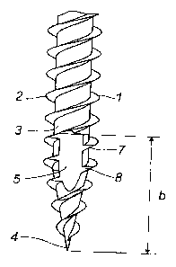
FIG. 1 is a front view of a portion of a screw according to the invention, and
FIG. 2 is a side view of the portion of FIG. 1.
Best Mode for Carrying out the Invention
The screw shown in the drawing includes two threads 1 and 2 extending in
parallel and around
the core 3 of the screw from a tapered end 4.
A plane recess 5, 6 is provided on each side of the screw, said recesses
extending parallel to one
another and parallel to the axis of the core. The recesses extend at such a
distance from the axis
of the core 3 that a segment of the core is cut off, said segment being of a
maximum height a
in the range from approximately 0.15 mm to approximately 0.5 mrn. The plane
recesses 5 and
6 extend from the tapered area of the screw in such a manner that the end
adjacent the tapered
end 4 also extends through the portions of the threads 1 and 2 within this
axea. Subsequently,
the recesses 5 and 6 extend upwards to a length b of from approximately 6.0 mm
to
approximately 14.0 mm from the tapered end of the screw. As a result, two
threaded cutting
edges 7, 7 are provided along the sides of the recesses 5 and 6, said threaded
cutting edges
cutting up the wood fibres during the screwing movement of the screw.
The above ranges of the lengths a and b depend on the dimension of each screw,
as two threaded
cutting edges 7 and 8 should, if possible, always be provided along the rirn
of the recess.

Representative Drawing
A single figure which represents the drawing illustrating the invention.
Administrative Status

2024-08-01:As part of the Next Generation Patents (NGP) transition, the Canadian Patents Database (CPD) now contains a more detailed Event History, which replicates the Event Log of our new back-office solution.

Please note that "Inactive:" events refers to events no longer in use in our new back-office solution.

For a clearer understanding of the status of the application/patent presented on this page, the site Disclaimer , as well as the definitions for Patent , Event History , Maintenance Fee  and Payment History  should be consulted.

Event History

Description Date
Time Limit for Reversal Expired 2011-07-14
Letter Sent 2010-07-14
Grant by Issuance 2009-04-07
Inactive: Cover page published 2009-04-06
Inactive: Final fee received 2009-01-19
Pre-grant 2009-01-19
Notice of Allowance is Issued 2008-07-22
Letter Sent 2008-07-22
Notice of Allowance is Issued 2008-07-22
Inactive: Approved for allowance (AFA) 2008-05-13
Amendment Received - Voluntary Amendment 2008-01-14
Amendment Received - Voluntary Amendment 2007-10-11
Inactive: S.30(2) Rules - Examiner requisition 2007-07-16
Amendment Received - Voluntary Amendment 2007-04-26
Application Published (Open to Public Inspection) 2007-01-14
Inactive: Cover page published 2007-01-14
Letter Sent 2005-10-28
Inactive: Single transfer 2005-10-12
Inactive: IPC assigned 2005-10-04
Inactive: First IPC assigned 2005-10-04
Inactive: Correspondence - Formalities 2005-09-07
Inactive: Filing certificate - RFE (English) 2005-08-23
Filing Requirements Determined Compliant 2005-08-23
Letter Sent 2005-08-23
Application Received - Regular National 2005-08-23
Request for Examination Requirements Determined Compliant 2005-07-14
All Requirements for Examination Determined Compliant 2005-07-14

Abandonment History

There is no abandonment history.

Maintenance Fee

The last payment was received on 2008-06-18

Note : If the full payment has not been received on or before the date indicated, a further fee may be required which may be one of the following

  • the reinstatement fee;
  • the late payment fee; or
  • additional fee to reverse deemed expiry.

Please refer to the CIPO Patent Fees web page to see all current fee amounts.

Fee History

Fee Type Anniversary Year Due Date Paid Date
Request for examination - standard 2005-07-14
Application fee - standard 2005-07-14
Registration of a document 2005-10-12
MF (application, 2nd anniv.) - standard 02 2007-07-16 2007-06-19
MF (application, 3rd anniv.) - standard 03 2008-07-14 2008-06-18
Final fee - standard 2009-01-19
MF (patent, 4th anniv.) - standard 2009-07-14 2009-06-17
Owners on Record

Note: Records showing the ownership history in alphabetical order.

Current Owners on Record
ITW CONSTRUCTION PRODUCTS APS
Past Owners on Record
MORTEN FRIIS BUHL
Past Owners that do not appear in the "Owners on Record" listing will appear in other documentation within the application.
Documents

To view selected files, please enter reCAPTCHA code :


To view images, click a link in the Document Description column. To download the documents, select one or more checkboxes in the first column and then click the "Download Selected in PDF format (Zip Archive)" or the "Download Selected as Single PDF" button.

List of published and non-published patent-specific documents on the CPD .

If you have any difficulty accessing content, you can call the Client Service Centre at 1-866-997-1936 or send them an e-mail at CIPO Client Service Centre.


Document
Description 
Date
(yyyy-mm-dd) 
Number of pages   Size of Image (KB) 
Abstract 2005-07-14 1 9
Description 2005-07-14 3 111
Claims 2005-07-14 1 20
Drawings 2005-07-14 1 14
Description 2005-09-07 3 112
Representative drawing 2006-12-28 1 6
Cover Page 2007-01-05 1 28
Claims 2008-01-14 2 49
Cover Page 2009-03-23 1 29
Acknowledgement of Request for Examination 2005-08-23 1 177
Filing Certificate (English) 2005-08-23 1 157
Courtesy - Certificate of registration (related document(s)) 2005-10-28 1 106
Reminder of maintenance fee due 2007-03-15 1 110
Commissioner's Notice - Application Found Allowable 2008-07-22 1 164
Maintenance Fee Notice 2010-08-25 1 170
Correspondence 2005-08-23 1 29
Correspondence 2005-09-07 3 110
Correspondence 2009-01-19 1 36