Language selection

Search

Patent 2512146 Summary

Third-party information liability

Some of the information on this Web page has been provided by external sources. The Government of Canada is not responsible for the accuracy, reliability or currency of the information supplied by external sources. Users wishing to rely upon this information should consult directly with the source of the information. Content provided by external sources is not subject to official languages, privacy and accessibility requirements.

Claims and Abstract availability

Any discrepancies in the text and image of the Claims and Abstract are due to differing posting times. Text of the Claims and Abstract are posted:

  • At the time the application is open to public inspection;
  • At the time of issue of the patent (grant).
(12) Patent: (11) CA 2512146
(54) English Title: HEIGHT ADJUSTMENT CLIP FOR AN ELEVATOR DOOR
(54) French Title: BRIDE DE REGLAGE DE HAUTEUR POUR PORTE D'ASCENSEUR
Status: Deemed expired
Bibliographic Data
(51) International Patent Classification (IPC):
  • B66B 13/30 (2006.01)
  • E05F 15/632 (2015.01)
  • E05D 15/06 (2006.01)
  • E05F 15/14 (2006.01)
(72) Inventors :
  • BASS, PATRICK M. (United States of America)
(73) Owners :
  • THYSSENKRUPP ELEVATOR CORPORATION (United States of America)
(71) Applicants :
  • THYSSEN ELEVATOR CAPITAL CORP. (United States of America)
(74) Agent: MLT AIKINS LLP
(74) Associate agent:
(45) Issued: 2010-03-30
(86) PCT Filing Date: 2004-01-15
(87) Open to Public Inspection: 2004-08-05
Examination requested: 2005-06-29
Availability of licence: N/A
(25) Language of filing: English

Patent Cooperation Treaty (PCT): Yes
(86) PCT Filing Number: PCT/US2004/001473
(87) International Publication Number: WO2004/065277
(85) National Entry: 2005-06-29

(30) Application Priority Data:
Application No. Country/Territory Date
10/348,440 United States of America 2003-01-21

Abstracts

English Abstract


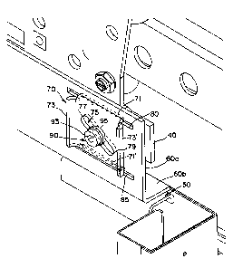
A height adjustment assembly connecting an elevator door to an elevator door
hanger comprises a door bracket (60), a plurality of door clip receiving
sections (80, 85) and corresponding number of door clips (70). Each door clip
comprises upper (71) and lower fins (71~), side fins, and an oblique slot (75)
disposed centrally between the fins. Each oblique slot is aligned with an
aperture in the receiving sections, and the upper and lower fins slidably
engage corresponding slots in the receiving sections. A fastener (90) inserted
into the oblique slot in the door clip and the aperture in the door bracket
holds the clip and the bracket onto the door hanger in a friction hold mode.
The height of the door may be adjusted by moving the door clips laterally in
the slots.


French Abstract

La présente invention a trait à un ensemble de réglage de hauteur reliant une porte d'ascenseur à un support de porte (60), une pluralité de sections de réception (80, 85) de brides de porte et un nombre correspondant de brides de porte (70). Chaque bride de porte comprime des nervures supérieures (71) et inférieures (71') et des nervures latérales, et une fente oblique (75) disposée au centre entre les nervures. Chaque fente oblique est alignée avec une ouverture dans les sections de réception, et les nervures supérieures et inférieures s'engagent en coulissement avec des fentes correspondantes dans les sections de réception. Une attache (90) introduite dans la fente oblique de la bride de porte et une ouverture dans le support de porte maintiennent la bride et le support sur le dispositif de guidage en un mode de maintien à frottement. La hauteur de la porte peut être réglée par le déplacement latérale des brides de porte dans les fentes.

Claims

Note: Claims are shown in the official language in which they were submitted.


What is claimed is:


1. A height adjustment assembly for connecting an elevator door to an elevator
door
hanger, the assembly comprising:

a bracket having a planar portion and an area for attachment to the top of the

elevator door;

a plurality of door clip receiving sections in the planar portion, each door
clip
receiving section comprising an upper slot and a lower slot oriented parallel
to
one another and an aperture between the upper and lower slots;

a plurality of door clips individually disposed in each door clip receiving
section,
each door clip comprising a body having an upper fin slidably engaging the
upper
slot of the door clip receiving section and a lower fin slidably engaging the
lower
slot of the door clip receiving section, and an oblique slot disposed between
the
fins and oriented obliquely with respect to the fins;

a fastener passing through the oblique slot and the aperture for frictionally
fastening the door clip and bracket to the door hanger;

wherein the height of the elevator door may be adjusted relative to the door
hanger by
moving the door clips laterally in the slots, which causes the fastener to
move along the
oblique slots on the door clips.

2. The height adjustment assembly of claim 1, further comprising one or more
lateral
tapping areas on each door clip for providing a tapping surface;

wherein each door clip may be moved laterally within the upper and lower slots
by
tapping on the tapping surfaces to move the oblique slot relative to the
fastener and
thereby raise or lower the door.

3. The height adjustment assembly of claim 2, wherein the assembly comprises
two


6


door clip receiving sections and two door clips.

4. The height adjustment assembly of claim 2, wherein the fastener is a nut
and a bolt.
5. The height adjustment assembly of claim 2, wherein the fastener is a bolt
threaded
into a threaded hole in the door hanger.

6. An elevator door and hanger having an height adjustment assembly
comprising:
an elevator door;

a door hanger for supporting the elevator door and allowing horizontal sliding

movement of the elevator door;

a height adjustment assembly connecting the elevator door to the door hanger,
the height adjustment assembly comprising;

a. a bracket having a planar portion and an area attached to the top of the
elevator door;

b. a plurality of door clip receiving sections in the planar portion, each
door clip
receiving section comprising an upper slot and a lower slot oriented parallel
to
one another and an aperture between the upper and lower slots;

c. a plurality of door clips individually disposed in each door clip receiving

section, each door clip comprising a body having an upper fin slidably
engaging
the upper slot of the door clip receiving section and a lower fin slidably
engaging
the lower slot of the door clip receiving section, and an oblique slot
disposed
between the fins and oriented obliquely with respect to the fins;

d. a fastener passing through the slot and the aperture and frictionally
fastening
the door dip and the bracket to the door hanger;

wherein the height of the door may be adjusted relative to the door hanger by
moving
the door clips laterally within the upper and lower slots of the door clip
receiving section,


7


which causes the oblique slots to move relative to the fastener.

7. The height adjustment assembly of claim 6, wherein the fastener is a nut
and a bolt.
8. The height adjustment assembly of claim 6, wherein the fastener is a bolt
threaded
into a threaded hole in the door hanger.

9. The height adjustment assembly of claim 6, further comprising one or more
lateral
tapping areas on each door clip for providing a tapping surface;

wherein the door clip may be moved laterally within the upper and lower slots
by tapping
on the tapping surfaces to move the oblique slot relative to the fastener and
thereby
raise or lower the door.

10. The height adjustment assembly of claim 9, wherein the assembly comprises
two
door dip receiving sections and two door clips.

11. A method of adjusting the height of an elevator door, comprising the steps
of:
providing a height adjustment assembly according to claim 1 for connecting an
elevator door to an elevator door hanger;

attaching the bracket of the height adjustment assembly to the top of the
elevator
door;

holding the bracket up against the elevator door hanger until the aperture in
each
of the receiving sections of the door bracket is aligned with a corresponding
hole
in the door hanger ready to receive a fastener;

placing a door clip within each of the receiving sections of the door bracket;

inserting a fastener through the oblique slot in the door clip, the aperture
in the
receiving section and in to the hole on the door hanger;


8


tightening the fastener to an adjustable state;

tapping the door clip until the door height is adjusted; and
tightening the fastener to a locked state.

12. The method according to claim 11, wherein the fastener is a nut and a
bolt.

13. The method according to claim 11, wherein the fastener is a bolt threaded
into a
threaded hole in the door hanger.

14. The method according to claim 11, wherein the adjustable state is achieved
by
tightening the fastener until the friction hold is sufficient to hold the door
against the door
hanger without slipping.

15. The method according to claim 11, wherein the door clip may be moved
laterally
Within the upper and lower slots by tapping on the tapping surfaces to move
the oblique
slot relative to the bolt and thereby raise or lower the door.

16. The method according to claim 11, wherein the lock state is achieved by
tightening
the fastener until the door clip and the door are fastened securely to the
door hanger.


9

Description

Note: Descriptions are shown in the official language in which they were submitted.


CA 02512146 2005-06-29
WO 2004/065277 PCT/US2004/001473
HEIGHT ADJUSTMENT CLIP FOR AN ELEVATOR DOOR
Field of the Invention
[0001] This invention relates to the field of elevator systems in general, and
more
particularly to a device for adjusting the height of elevator doors.
Background of the Invention
[0002] Elevator doors in general require adjustment to fit properly into the
opening of an
elevator car. Conventionally, an elevator door is hung on a door hanger.
[0003] It is often necessary to make fine adjustments to the height of the
elevator doors
once the doors are hung on the hanger. For example, after a door is hung, it
may be
desirable to raise or lower it slightly to provide the proper clearance
between the bottom
of the door and the doorsill at the entry of the cab. Conventional doors allow
for
adjustment in height by providing bolt and slot configurations where the door
is fastened
to the hanger. The weight of the door makes adjustment cumbersome and usually
requires more than one worker. One worker must raise or lower the door to the
desired
position while a second worker tightens the fastener. It would therefore be
desirable to
provide a height adjustment assembly for an elevator door that may be used
easily and
by only one worker hanging the door.
Summary of the Invention
[0004] The present invention concerns a height adjustment assembly for fitting
elevator
doors into the door opening of an elevator car and a method of adjusting the
height of
elevator while the door is being fitted into the door opening.
[0005] In one embodiment of the present invention, the assembly comprises a
bracket
having a planar portion and an area for attachment to the top of the elevator
door. The
planar portion further comprises a plurality of door clip receiving sections,
each door clip
receiving section having an upper slot and a lower slot oriented parallel to
one another
and an aperture between the upper and lower slots. A plurality of door clips
is provided,
and each clip is disposed in a receiving section. Each door clip has a body
having an
upper fin slidably engaging the upper slot of the receiving section and a
lower fin
slidably engaging the lower slot of the receiving section. The door clip also
has a slot
between the fins and oriented obliquely with respect to the fins. A fastener
passes
through the slot and the aperture for frictionally holding the door clip and
bracket to the


CA 02512146 2005-06-29
WO 2004/065277 PCT/US2004/001473
door hanger. The height of the elevator door can then be adjusted relative to
the door
hanger device by moving the door clips laterally in the slots, which causes
the oblique
slot to move along the fastener and thereby vertically raise or lower the
door.
[0006] The invention also concerns an elevator door and hanger having a height
adjustment assembly comprising an elevator door; a hanger for supporting the
elevator
door and allowing horizontal sliding movement of the door; and the height
adjustment
assembly of the invention connecting the elevator door to the door hanger.
[0007] The invention also concerns a method of adjusting the height of an
elevator
door. The method includes providing a height adjustment assembly according to
the
invention. The door bracket of the assembly is atttached to the top of an
elevator door.
The door bracket is then held up against the door hanger until the aperture in
each of
the receiving sections of the door bracket is lined up with a corresponding
hole in the
door hanger ready to receive a fastener. A door clip is then placed within
each of the
receiving sections of the door bracket while aligning the oblique slot in the
door clip with
the fastener. Next, the upper and lower fins of the door clip are inserted
into the
corresponding upper and lower slots in the receiving sections of the door
bracket.
Gravity drops the door to a low position on the door hanger. While in the low
position,
the fastener is tightened to an adjustable state where the tightness provides
sufficient
friction to hold the door against the door hanger without slipping on the
fastener. In the
adjustable state, the fastener is not too tight to allow incremental movements
of the
oblique over the fastener when the clip is tapped. Then, small blows or taps
on the side
fins of the door clip move the door clip laterally within the upper and lower
slots and the
oblique slot relative to the fastener, thereby raising or lowering the door.
When the
desired door height is achieved, the fastener is tightened to a lock state to
lock the door
to the door hanger securely.
Brief Description of the Drawings
[0008] Figure 1 is an embodiment of the present invention showing a height
adjustment
assembly for connecting an elevator door to an elevator door hanger.
(0009] Figure 2 shows a door hanger, set of door clips, and a door bracket
adapted to
receive the clips, according to the present invention.
[0010] Figure 3A shows a fastener holding a door clip and the door bracket
onto the
door hanger, according to the present invention.
2


CA 02512146 2005-06-29
WO 2004/065277 PCT/US2004/001473
[0011] Figure 3B shows a door bracket having upper and lower slots and an
aperture
disposed centrally between the slots, according to the present invention.
[0012] Figure 4 shows a door clip, according to the present invention.
[0013] Figure 5a shows the displacement of the door of Figure 3 in an upward
direction
when one of the side fins of the door clip is tapped in the corresponding
direction,
according to the present invention.
[0014] Figure 5b shows the displacement of the door of Figure 3 in a downward
direction when one of the side fins of the door clip are tapped in the
corresponding
direction, according to the present invention.
Detailed Description
[0015] Figure 1 shows the basic structure of an elevator car 13 in a sling
having stiles
20, bolster 17, and header 30. Stiles 20 and header 30 form a frame around the
door
opening. Door header 30 supports door hangers 40. Doors 50 hang from the door
hangers 40.
[0016] As shown in Figure 2, each door 50 is attached to its corresponding
door hanger
40 by a height adjustment assembly of the invention. The height adjustment
assembly
includes a door bracket 60 having vertical planar portion 60a and preferably a
right-
angle area 60b for attachment to the top of elevator door 50. The planar
portion 60a
provides sections to receive a plurality of door clips 70 that are used for
attaching the
bracket 60 to the hanger 40 and for adjusting the height of the doors. It is
preferred that
the two proximate end sections of the bracket are used for this purpose.
[0017] As shown in Figure 3A, each door clip receiving section comprises upper
slot 80
and lower slot 85, each slot adapted to receive a portion of door clip 70. An
aperture 87
is also included between the slots 80 and 85 (See Figure 3B). Door clip 70
comprises a
body having upper fin portion 71 and lower fin portion 71' (Also see Figure
4). Each fin
71 and 71' is formed outwardly from the planar body of the clip in order to
slidably
engage the corresponding upper and lower slots 80 and 85, respectively. The
slots 80
and 85 are substantially wider than the width of fins 71 and 71' so that the
fins can
easily move laterally within their respective slots. Door clip 70 preferably
includes
additional side fins 73 and 73' that are formed in a direction opposite to
that of the upper
and lower fins. The side fins provide tapping surfaces that allow the worker
to tap the
clip and move it laterally within the slots 80 and 85. A slot 75 is disposed
between fins
3


CA 02512146 2005-06-29
WO 2004/065277 PCT/US2004/001473
71 and 71', and oriented obliquely with respect to the fins. As shown in
Figure 4,
oblique slot 75 is preferably formed centrally in clip 70 along axis 75'
aligned diagonally
with respect to the vertices of the clip.
[0018] Referring again to Figure 3A, door 50 is attached to area 60b of
bracket 60.
Bracket 60 with door 50 attached thereto is then held up against door hanger
40 so that
aperture 87 of bracket 60 is aligned with a hole in door hanger 40 ready to
receive a
fastener. Door clip 70 is then placed within the receiving section with door
clip fins 71
and 71' aligned in upper and lower slots 80 and 85 and with oblique slot 75
aligned with
aperture 87 in bracket 60 and with the hole in hanger 40. A fastener, such as
bolt 90,
passes through oblique slot 75 in each clip, and through aperture 87 of door
bracket 60
and to the hole in door hanger 40, thereby fastening the clip and the door
bracket to the
door hanger. When the door is simply hung on to the door hanger without the
tightening
the bolt, that is, with the bolt in a "loose state," the door will, by
gravity, drop to the "low
position," with upper end 77 of oblique slot 75 shown in Figure 3A resting on
bolt 90 as
shown in Figure 5a. In other words, the weight of the door will make it slide,
riding bolt
90 down the oblique slot. At the same time, upper and lower fins 71 and 71',
respectively, will move laterally to the right in their corresponding slots 80
and 85. On
the other hand, the door can be lifted upwards so that the clip now rides
upwards until
bolt stops at lower end 79 of the oblique slot while the upper and lower fins
move
laterally to the left as shown in Figure 5b. In order to hold the door in the
"up position,"
the bolt is tightened so that bearing surface 95 (such as a washer) of the
bolt locks the
door in the desired position.
[0019] The door height can be adjusted from the natural "low" position to any
height
within specifications through incremental steps. This is accomplished by
tightening the
bolt to provide sufficient friction hold on the door against the door hanger
while the door
is preferably in approximately the center position as shown in Figure 3A.
Then, small
blows or taps on the side fins, namely, on fins 73 and 73' that provide
tapping surfaces,
advance the clips left or right, depending upon which fin is tapped. With each
tap,
therefore, the door moves vertically, that is, up or down. The tightness of
the bolt is
such that in its "adjustable state," the friction hold is sufficient to hold
the weight of the
door against the door hanger without slipping on the bolt, and yet not so
tight as to
prevent incremental movement along the oblique slot with each tap. After
proper
adjustment, the bolt is tightened to a "lock state" to hold the door securely
in place.
4


CA 02512146 2005-06-29
WO 2004/065277 PCT/US2004/001473
[0020] While the invention has been particularly shown and described with
reference to
particular embodiments, those skilled in the art will understand that various
changes in
form and details may be made without departing form the spirit and scope of
the
invention.

Representative Drawing
A single figure which represents the drawing illustrating the invention.
Administrative Status

For a clearer understanding of the status of the application/patent presented on this page, the site Disclaimer , as well as the definitions for Patent , Administrative Status , Maintenance Fee  and Payment History  should be consulted.

Administrative Status

Title Date
Forecasted Issue Date 2010-03-30
(86) PCT Filing Date 2004-01-15
(87) PCT Publication Date 2004-08-05
(85) National Entry 2005-06-29
Examination Requested 2005-06-29
(45) Issued 2010-03-30
Deemed Expired 2019-01-15

Abandonment History

Abandonment Date Reason Reinstatement Date
2008-01-21 R30(2) - Failure to Respond 2008-11-25

Payment History

Fee Type Anniversary Year Due Date Amount Paid Paid Date
Request for Examination $800.00 2005-06-29
Registration of a document - section 124 $100.00 2005-06-29
Application Fee $400.00 2005-06-29
Maintenance Fee - Application - New Act 2 2006-01-16 $100.00 2006-01-06
Maintenance Fee - Application - New Act 3 2007-01-15 $100.00 2006-12-28
Maintenance Fee - Application - New Act 4 2008-01-15 $100.00 2008-01-10
Reinstatement - failure to respond to examiners report $200.00 2008-11-25
Maintenance Fee - Application - New Act 5 2009-01-15 $200.00 2009-01-02
Final Fee $300.00 2009-12-01
Maintenance Fee - Application - New Act 6 2010-01-15 $200.00 2009-12-29
Maintenance Fee - Patent - New Act 7 2011-01-17 $200.00 2010-12-30
Maintenance Fee - Patent - New Act 8 2012-01-16 $200.00 2011-12-29
Maintenance Fee - Patent - New Act 9 2013-01-15 $200.00 2012-12-31
Maintenance Fee - Patent - New Act 10 2014-01-15 $250.00 2014-01-06
Registration of a document - section 124 $100.00 2014-03-17
Maintenance Fee - Patent - New Act 11 2015-01-15 $250.00 2015-01-05
Maintenance Fee - Patent - New Act 12 2016-01-15 $250.00 2016-01-04
Maintenance Fee - Patent - New Act 13 2017-01-16 $250.00 2017-01-02
Owners on Record

Note: Records showing the ownership history in alphabetical order.

Current Owners on Record
THYSSENKRUPP ELEVATOR CORPORATION
Past Owners on Record
BASS, PATRICK M.
THYSSEN ELEVATOR CAPITAL CORP.
Past Owners that do not appear in the "Owners on Record" listing will appear in other documentation within the application.
Documents

To view selected files, please enter reCAPTCHA code :


To view images, click a link in the Document Description column. To download the documents, select one or more checkboxes in the first column and then click the "Download Selected in PDF format (Zip Archive)" or the "Download Selected as Single PDF" button.

List of published and non-published patent-specific documents on the CPD .

If you have any difficulty accessing content, you can call the Client Service Centre at 1-866-997-1936 or send them an e-mail at CIPO Client Service Centre.


Document
Description 
Date
(yyyy-mm-dd) 
Number of pages   Size of Image (KB) 
Claims 2008-11-25 4 112
Cover Page 2010-03-05 2 50
Claims 2009-03-18 4 124
Abstract 2005-06-29 2 74
Claims 2005-06-29 3 124
Drawings 2005-06-29 5 100
Description 2005-06-29 5 227
Representative Drawing 2005-09-22 1 11
Cover Page 2005-09-23 1 44
Prosecution-Amendment 2009-03-19 7 195
Prosecution-Amendment 2009-03-19 7 185
PCT 2005-06-29 3 81
Assignment 2005-06-29 8 282
Fees 2006-01-06 3 69
Prosecution-Amendment 2009-02-13 1 28
Fees 2006-12-28 4 114
Prosecution-Amendment 2007-07-20 2 47
Fees 2008-01-10 4 122
Prosecution-Amendment 2008-11-25 7 230
PCT 2005-06-29 5 203
Fees 2009-01-02 6 157
Correspondence 2009-12-01 3 84
Fees 2009-12-29 3 118
Assignment 2014-03-17 21 1,342
Correspondence 2014-04-09 1 16
Correspondence 2015-03-02 2 102
Office Letter 2016-06-09 1 41
Change of Agent 2016-06-06 5 189
Office Letter 2016-07-22 2 30
Office Letter 2016-07-22 2 29