Some of the information on this Web page has been provided by external sources. The Government of Canada is not responsible for the accuracy, reliability or currency of the information supplied by external sources. Users wishing to rely upon this information should consult directly with the source of the information. Content provided by external sources is not subject to official languages, privacy and accessibility requirements.
Any discrepancies in the text and image of the Claims and Abstract are due to differing posting times. Text of the Claims and Abstract are posted:
| (12) Patent Application: | (11) CA 2512246 |
|---|---|
| (54) English Title: | APPARATUS FOR CONNECTING A BATTERY PLATE TO A METAL STRAP OR POST |
| (54) French Title: | APPAREIL PERMETTANT DE CONNECTER UNE PLAQUE D'ACCUMULATEUR A UN ETRIER OU UNE BARRETTE METALLIQUE |
| Status: | Deemed Abandoned and Beyond the Period of Reinstatement - Pending Response to Notice of Disregarded Communication |
| (51) International Patent Classification (IPC): |
|
|---|---|
| (72) Inventors : |
|
| (73) Owners : |
|
| (71) Applicants : |
|
| (74) Agent: | OSLER, HOSKIN & HARCOURT LLP |
| (74) Associate agent: | |
| (45) Issued: | |
| (86) PCT Filing Date: | 2003-12-19 |
| (87) Open to Public Inspection: | 2004-08-12 |
| Examination requested: | 2008-07-14 |
| Availability of licence: | N/A |
| Dedicated to the Public: | N/A |
| (25) Language of filing: | English |
| Patent Cooperation Treaty (PCT): | Yes |
|---|---|
| (86) PCT Filing Number: | PCT/GB2003/005562 |
| (87) International Publication Number: | WO 2004067208 |
| (85) National Entry: | 2005-06-29 |
| (30) Application Priority Data: | ||||||
|---|---|---|---|---|---|---|
|
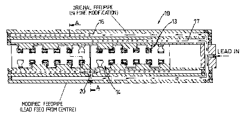
This invention relates to apparatus for connecting a battery plate to a metal
strap or post or to moulds therefor. In contrast to existing arrangements lead
is fed to the feed passage (17) via an opening (20) which is positioned
immediate the ends of the aligned cavities in the set (14) of the mould. This
arrangement enables the cavities to be fed with lead at approximately the same
time and hence the dip of the lugs into the cavities can be optimised without
any significant difficulties. In itself this substantially increases
productivity. It has also been found that up to three batteries can be cast
simultaneously, particularly if bypasses (16c) are used for fine tuning the
lead supply.
Appareil permettant de connecter une plaque d'accumulateur à un étrier ou une barrette métallique ou à des moules pour lesdits étriers ou barrettes. Par rapport aux systèmes existants, le plomb est introduit dans le passage d'alimentation (17) via une ouverture (20) qui est placée à proximité immédiate des extrémités des cavités alignées de la série de cavités (14) du moule. Cette configuration permet le remplissage des cavités approximativement au même moment, et par conséquent l'immersion des languettes dans les cavités peut être optimisé sans difficultés significatives. En soi, cela augmente considérablement la productivité. Il a également été découvert que jusqu'à trois accumulateurs peuvent moulés simultanément, en particulier si des dérivations (16c) sont utilisées pour ajuster précisément l'alimentation en plomb.
Note: Claims are shown in the official language in which they were submitted.
Note: Descriptions are shown in the official language in which they were submitted.
2024-08-01:As part of the Next Generation Patents (NGP) transition, the Canadian Patents Database (CPD) now contains a more detailed Event History, which replicates the Event Log of our new back-office solution.
Please note that "Inactive:" events refers to events no longer in use in our new back-office solution.
For a clearer understanding of the status of the application/patent presented on this page, the site Disclaimer , as well as the definitions for Patent , Event History , Maintenance Fee and Payment History should be consulted.
| Description | Date |
|---|---|
| Inactive: IPC from PCS | 2021-10-16 |
| Inactive: Agents merged | 2013-10-31 |
| Time Limit for Reversal Expired | 2010-12-20 |
| Application Not Reinstated by Deadline | 2010-12-20 |
| Inactive: Abandoned - No reply to s.30(2) Rules requisition | 2010-05-03 |
| Deemed Abandoned - Failure to Respond to Maintenance Fee Notice | 2009-12-21 |
| Inactive: S.30(2) Rules - Examiner requisition | 2009-11-03 |
| Letter Sent | 2008-10-20 |
| All Requirements for Examination Determined Compliant | 2008-07-14 |
| Request for Examination Received | 2008-07-14 |
| Request for Examination Requirements Determined Compliant | 2008-07-14 |
| Letter Sent | 2006-03-29 |
| Inactive: Single transfer | 2006-02-23 |
| Inactive: Courtesy letter - Evidence | 2005-09-27 |
| Inactive: Cover page published | 2005-09-26 |
| Inactive: Notice - National entry - No RFE | 2005-09-20 |
| Application Received - PCT | 2005-08-24 |
| National Entry Requirements Determined Compliant | 2005-06-29 |
| Application Published (Open to Public Inspection) | 2004-08-12 |
| Abandonment Date | Reason | Reinstatement Date |
|---|---|---|
| 2009-12-21 |
The last payment was received on 2008-12-08
Note : If the full payment has not been received on or before the date indicated, a further fee may be required which may be one of the following
Please refer to the CIPO Patent Fees web page to see all current fee amounts.
| Fee Type | Anniversary Year | Due Date | Paid Date |
|---|---|---|---|
| Basic national fee - standard | 2005-06-29 | ||
| MF (application, 2nd anniv.) - standard | 02 | 2005-12-19 | 2005-12-19 |
| Registration of a document | 2006-02-23 | ||
| MF (application, 3rd anniv.) - standard | 03 | 2006-12-19 | 2006-12-05 |
| MF (application, 4th anniv.) - standard | 04 | 2007-12-19 | 2007-12-06 |
| Request for examination - standard | 2008-07-14 | ||
| MF (application, 5th anniv.) - standard | 05 | 2008-12-19 | 2008-12-08 |
Note: Records showing the ownership history in alphabetical order.
| Current Owners on Record |
|---|
| TBS ENGINEERING LIMITED |
| Past Owners on Record |
|---|
| CHRISTOPHER BARGE |
| ROBERT HOPWOOD |

