Note: Descriptions are shown in the official language in which they were submitted.
CA 02512318 2005-07-18
HEAT EXCHANGERS WITH CORRUGATED HEAT EXCHANGE ELEMENTS
OF IMPROVED STRENGTH
FIELD OF THE INVENTION
The invention relates to heat exchangers and corrugated heat exchange elements
for use therein, and particularly to corrugated heat exchanger fins and
turbulizers
of improved strength and manufacturability, and to heat exchangers
incorporating
such fins and turbulizers.
BACKGROUND OF THE INVENTION
Heat exchangers are commonly provided with heat exchange elements such as
corrugated fins and/or turbulizers in order to enhance heat transfer between
two
or more fluids. Corrugated fins and turbulizers are structurally similar, and
typically comprise a thin metal sheet in which parallel bends define a series
of
corrugations of a generally rectangular or triangular form. A turbulizer is
generally
inserted inside a fluid flow passage defined by the interior of a tube or a
plate pair,
whereas a fin is generally mounted on an exterior surface of a tube or plate
pair.
The fluids which come into contact with these heat exchange elements may be on
the hot or cold heat transfer side and may consist of gaseous, liquid or two-
phase
fluids.
Corrugated heat exchange elements can take the form of corrugated turbulizers
such as those described in U.S. Patent No. 4,945,981 (Joshi) issued on August
7,
1990. Joshi describes an automotive oil cooler comprising a pair of plates
defining an oil passage with a turbulizer inserted therein. The Joshi
turbulizer
comprises a metal foil having a plurality of parallel V-shaped corrugations
and is
orientated in the oil passage with the longitudinal direction of the
corrugations
extending either parallel or transverse to the direction of oil flow. The top
and
bottom surfaces of the corrugations are in heat exchange contact with the
plates
of the oil cooler and are preferably brazed to the plates. The side surface of
each
CA 02512318 2005-07-18
2
corrugation is provided with a series of louvers which create turbulence in
the oil
and enhance heat transfer. Where the corrugations are transverse to the flow
direction, the oil must flow through the louver openings in order to pass from
the
inlet to the outlet.
One disadvantage of the Joshi turbulizer is that the triangular or V-shaped
corrugations make contact with the plates only along the relatively narrow top
and
bottom surfaces of the turbulizer, thereby limiting heat transfer.
Furthermore, the
sloping side walls of the Joshi turbulizer result in the formation of
relatively large
spaces between adjacent side walls. Where the corrugations are aligned
parallel
to the direction of fluid flow, there is significant duct flow between the
side walls,
which results in poor heat transfer.
Heat exchange elements having rectangular corrugations, with substantially
vertical side walls and flat top and bottom walls, are preferred over those of
Joshi
because the relatively constant spacing between adjacent side walls provides
reduced duct flow as compared to inserts with V-shaped corrugations.
However, the formation of rectangular corrugations involves additional bending
operations, with the top and bottom wall of each corrugation being defined by
a
pair of closely-spaced substantially 90-degree bends. The metal foil used in
these inserts is very thin and therefore it is difficult to form clean bends
along the
edges of the top and bottom walls.
In order to ensure that the top and bottom walls of the corrugations are in
contact
with the plates or tubes of the heat exchanger, these corrugated heat exchange
elements are usually compressed between the plates or tubes during assembly.
Due to the thinness of the foil, the heat exchange elements can be easily
crushed
by this compression, resulting in irreparable damage to the heat exchanger.
While the strength of the corrugated heat exchange element may be improved by
CA 02512318 2005-07-18
3
the provision of louvers, this improvement is sometimes insufficient to resist
crushing during assembly. Furthermore, in conventional louvered fins or
turbulizers as taught by Joshi, there is an unsupported area between the ends
of
the louvers and the top and bottom walls. This unsupported area is
particularly
vulnerable to crushing during assembly of the heat exchanger.
There is a need for corrugated heat exchange elements having improved
strength, manufacturability, thermal performance and/or reduced gauge, and
which preferably comprise corrugations with generally flat top and bottom
walls.
SUMMARY OF THE INVENTION
In one aspect, the present invention provides a corrugated heat exchange
element for a heat exchanger, the heat exchange element comprising a plurality
of side walls interconnected by a plurality of top and bottom walls, wherein
each
of the side walls defines a plane and extends parallel to a longitudinal axis,
wherein each of the side walls extends between an adjacent one of the top
walls
and an adjacent one of the bottom walls, and wherein longitudinal bends are
formed between each side wall and the adjacent top and bottom walls such that
spaces for flow of a heat exchange fluid are defined between adjacent ones of
said side walls; and at least one group of adjacent louvers provided in at
least
some of the side walls, wherein each group of adjacent louvers is defined by a
plurality of parallel slits extending between the top wall and the bottom wall
of the
side wall substantially perpendicular to the axis; wherein each of the
adjacent
louvers comprises an area of the side wall between an adjacent pair of said
slits
and includes: (i) a first edge extending along a first slit of the adjacent
pair of slits;
(ii) a second edge extending along a second slit of the adjacent pair of
slits; and
(iii) at least one bend located between the first and second edges of the
louver
which causes at least one of the edges of the louver to project outwardly of
the
plane of the side wall.
CA 02512318 2005-07-18
4
In another aspect, the present invention provides a corrugated heat exchange
element for a heat exchanger, the heat exchange element comprising a plurality
of side walls interconnected by a plurality of top and bottom walls, wherein
each
of the side walls defines a plane and extends parallel to a longitudinal axis,
wherein each of the side walls extends between an adjacent one of the top
walls
and an adjacent one of the bottom walls, and wherein longitudinal bends are
formed between each side wall and the adjacent top and bottom walls such that
spaces for flow of a heat exchange fluid are defined between adjacent ones of
said side walls; wherein each of the top walls of the heat exchange element
extends between a pair of longitudinal bends through which it is joined to
adjacent
ones of said side walls, and wherein each of the bottom walls of the heat
exchange element extends between a pair of longitudinal bends through which it
is joined to adjacent ones of said side walls; wherein embossments are
provided
in at least some of the top walls and at least some of the bottom walls of the
heat
exchange element; and wherein each of the embossments in the top walls cause
portions of said top walls to deviate away from the top plane of the heat
exchange
element in a direction toward the bottom plane of the heat exchange element,
and
wherein the embossments in the bottom walls cause portions of said bottom
walls
to deviate away from the bottom plane of the heat exchange element in a
direction toward the top plane of the heat exchange element.
In yet another aspect, the present invention provides a plate-type heat
exchanger
comprising a pair of plates secured together at their margins and spaced from
one
another between the margins to form a fluid flow passage, the fluid flow
passage
having a height and having an inlet opening and an outlet opening spaced apart
along a plate axis. A corrugated heat exchange element according to the
invention is received inside said fluid flow passage and is located between
the
inlet and outlet openings with its top and bottom walls in contact with the
plates.
CA 02512318 2005-07-18
s
BRIEF DESCRIPTION OF THE DRAWINGS
The invention will now be described, by way of example only, with reference to
the accompanying drawings in which:
Figure 1 is a perspective view of a preferred corrugated heat exchange element
according to the invention;
Figure 2 is a cross section along line 2-2 of Figure 1;
Figure 3 is a cross section along line 3-3 of Figure 1;
Figure 4 is a cross section along line 4-4 of Figure 1;
Figure 5 is a cross section of a corrugated heat exchange element according to
a
another preferred embodiment of the invention;
Figure 6 is cross sectional end view of the corrugated heat exchange element
shown in Figure 5;
Figure 7 is a cross section of a portion of a corrugated heat exchange element
according to another preferred embodiment of the invention;
Figure 8 is a cross section of a portion of a corrugated heat exchange element
according to another preferred embodiment of the invention;
Figure 9 is a cross section of a portion of a corrugated heat exchange element
according to another preferred embodiment of the invention;
Figures 10 to 14 illustrate corrugated heat exchange elements according to the
invention having various types of protrusions in their top and bottom walls;
CA 02512318 2005-07-18
6
Figure 15 is a plan view of a flattened section of corrugated heat exchange
element of Figures 1 to 4;
Figure 16 is a plan view of a flattened section of corrugated heat exchange
element according to another preferred embodiment of the invention;
Figure 17 is a cut-away perspective view of a plate-type heat exchanger
incorporating the corrugated heat exchange element of Figures 1 to 4;
Figure 18 is a cross section along line 18-18 of Figure 17;
Figure 19 is cross section through a preferred heat exchange element according
to the invention having trapezoidal corrugations;
Figure 20 is a cross sectional end view through a heat exchange element with
triangular corrugations according to the invention;
Figure 21 is a cross section through the side wall of a heat exchange element
according to another preferred embodiment of the invention;
Figure 22 is a cross section through the side wall of a heat exchange element
according to another preferred embodiment of the invention; and
Figure 23 is a perspective view of a corrugated heat exchange element
according
to the invention having protrusions formed in its top and bottom walls.
DETAILED DESCRIPTION OF PREFERRED EMBODIMENTS
The following is a detailed description of preferred corrugated heat exchange
elements according to the invention, as well as preferred heat exchangers in
which they are used. As used herein, the term "corrugated heat exchange
CA 02512318 2005-07-18
7
element" is intended to include both corrugated fins and turbulizers which, as
mentioned above, are structurally similar and differ primarily in the way they
are
incorporated into heat exchangers.
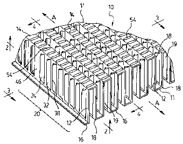
A first preferred corrugated heat exchange element 10 according to the
invention
is now described with reference to Figures 1 to 4. Heat exchange element 10
comprises a plurality of corrugations 11 extending along a longitudinal axis
A, the
corrugations 11 being defined by a plurality of spaced-apart side walls 12
interconnected by a plurality of top and bottom walls 14, 16. Each side wall
12
defines a plane S (Figure 2) and extends parallel to axis A. Each of the side
walls
12 has a height H and extends between an adjacent top wall 14 and an adjacent
bottom wall 16 of the heat exchange element 10 and is joined to the adjacent
top
and bottom walls 14, 16 by longitudinal bends 18 such that spaces 19 for flow
of a
heat exchange fluid are defined between adjacent pairs of side walls 12.
Height
H is defined as the distance measured along the side walls 12 between the top
and bottom walls 14, 16. Although terms such as "top", "bottom", "upper" and
"lower" are used herein, it is to be appreciated that these terms are used for
convenience only. The top and bottom of heat exchange element 10 are
preferably indistinguishable from each other. Furthermore, it is to be
appreciated
that the drawings illustrating the preferred embodiments are not necessarily
to
scale, and certain features are exaggerated in order to better explain the
invention.
In the first preferred embodiment described herein, the corrugations 11 and
the
spaces 19 between adjacent side walls 12 are substantially rectangular, having
substantially flat top and bottom walls 14, 16 and side walls 12 which are
substantially parallel to one another along their entire height H and with
longitudinal bends 18 having an angle of about 90 degrees.
CA 02512318 2005-07-18
g
The top and bottom walls 14, 16 of heat exchange element 10 are generally flat
and parallel to one another and have a width W, which is defined as a
transverse
distance between an adjacent pair of longitudinal bends 18 through which they
are joined to adjacent side walls 12. The top and bottom walls 14,16 define
respective top and bottom planes T and B of the heat exchange element 10,
wherein each of the longitudinal bends 18 is located in either the top plane T
or
the bottom plane B. In the first preferred heat exchange element 10, all the
top
walls 14 are preferably located in top plane T and all the bottom walls 16 are
preferably located in bottom plane B. It will, however, be appreciated that
this is
not necessarily the case and that the objects of the invention can be achieved
where the height H of the side walls 12 is varied, for example to conform to
an
irregularly-shaped fluid flow passage.
At least some of the side walls 12 of the corrugated heat exchange element 10
are provided with one or more groups 20 of closely-spaced louvers 24. In the
first
preferred embodiment, each side wall 12 is provided with two groups 20 of
louvers 24. Each group 20 of louvers 24 is defined by a plurality of parallel
slits
22 formed in the side wall 12 and extending substantially between the top and
bottom walls 14, 16. In the first preferred embodiment, the slits 22 are
substantially perpendicular to the axis A and are spaced equidistantly from
one
another.
Adjacent groups 20 of louvers 24 may preferably be spaced apart by a distance
which is greater than the spacing between adjacent slits 22. In the first
preferred
embodiment, the groups 20 of louvers 24 are separated by a dividing web 46
which is located in the plane S of the side wall 12. It will, however, be
appreciated
that the provision of dividing web 46 between the groups 20 of louvers 24 is
not
necessary.
CA 02512318 2005-07-18
9
Each of the adjacent louvers 24 within each group 20 comprises an area of the
side wall 12 between an adjacent pair of slits 22 and includes a first edge 28
extending along one slit 22 and a second edge 30 extending along an adjacent
slit 22. Each of the louvers 24 further comprises at least one bend located
between the first and second edges 28, 30. In the first preferred embodiment,
there is a single, angular bend 26 provided between the first and second edges
28, 30 of each louver 24. Preferably, the bend 26 is located approximately
midway between the edges 28, 30, although this is not necessarily the case.
The
bend 26 extends along a line which is substantially parallel to the edges 28,
30 of
the louver 24 and extends throughout substantially the entire height of louver
24.
The bend 26 also defines an apex 34 of the louver 24, the apex 34 being
located
in the plane S of the side wall 12. The apex 34 divides the louver 24 into a
substantially flat first louver wall 32 and a substantially flat second louver
wall 38
which meet at the apex 34 and extend from the apex 34 to the respective first
and
second edges 28, 30 of louver 24.
The bend 26 defines an angle a' between the first and second louver walls 32,
38. The provision of bend 26 between the edges 28, 30 of louvers 24 causes at
least one of the edges of the louver 24 to project outwardly of the plane S of
the
side wall 12, thereby providing gaps 40 through which the heat exchange fluid
can flow through the side walls 12.
In the first preferred embodiment, the louvers 24 are of the "one-sided" type,
meaning that only the first edge 28 (and the first wall 32) of each louver 24
projects outwardly of the plane S of the side wall 12, while the second edge
30
(and the second wall 38) of the louver 24 is located in plane S. Furthermore,
the
first edges 28 of all the louvers 24 within each group 20 project outwardly
from the
same side of the side wall 12. In preferred embodiments where the heat
exchange element 10 is orientated such that the flow of heat exchange fluid is
parallel to axis A, i.e. the "low pressure drop" orientation, the first louver
wall 32 is
CA 02512318 2005-07-18
preferably at an angle ~3' of about 20 to 30 degrees relative to plane S, with
angle
a' being 180 - Vii'. In the first preferred embodiment, the angles a' and Vii'
are the
same for all the louvers 24, although this is not necessarily the case.
Furthermore, each louver 24 projects outwardly of the side wall 12 by the same
amount, although this is not necessary either.
As shown in the drawings, the louvers 24 within each group 20 face in the same
direction, i.e. each of the slits 22 is bounded by the first edge 28 of one of
the
louvers 24 and the second edge 30 of an adjacent one of the louvers 24.
Moreover, the louvers 24 of the two groups 20 preferably face the same
direction,
and preferably project from opposite sides of the side wall 12.
Figures 5 to 8 illustrate corrugated heat exchange elements according to other
preferred embodiments of the invention in which the louvers are two-sided,
i.e.
each louver projects outwardly from both sides of the side wall. Two-sided
louvers provide improved heat transfer because they disrupt fluid flow along
both
sides of the side wall and provide better transition of fluid flow from one
side wall
to another than one-sided louvers.
Figures 5 and 6 illustrate a second preferred corrugated heat exchange element
72 according to the invention which incorporates two-sided louvers 74. Heat
exchange element 72 comprises a plurality of corrugations 76 extending along
longitudinal axis A, the corrugations 76 having generally the same rectangular
shape as the corrugations 11 of heat exchange element 10 described above.
Corrugations 76 are defined by a plurality of spaced-apart side walls 78
interconnected by a plurality of top and bottom walls 80, 82. Each side wall
78
defines a plane S and is parallel to the axis A. The side walls 78 and walls
80, 82
are joined by longitudinal bends 84, each bend 84 defining an angle of about
90
degrees and being located in a top plane T or a bottom plane B of the heat
exchange element 72.
CA 02512318 2005-07-18
11
Figure 5 is a cross section through one of the side walls 78, taken in a plane
corresponding to that of Figure 2, showing that the louvers 74 are arranged in
much the same way as louvers 24 of heat exchange element 10, i.e. the louvers
74 are arranged as two groups 86 separated by a dividing web 88. Each group
86 of louvers 74 is defined by a plurality of parallel, equidistantly spaced
slits 90
formed in the side wall 78 and extending between the top and bottom walls 80,
82.
Each of the adjacent louvers 74 within each group 86 comprises an area of the
side wall 78 between an adjacent pair of slits 90 and includes a first edge 92
extending along one of the slits 90 and a second edge 94 extending along an
adjacent slit 90. Each of the louvers 74 further comprises a single, angular
bend
96 provided approximately midway between the edges 92, 94, similar to louvers
24 described above, and extending along a bend line which is substantially
parallel to edges 92, 94. The bend 96 defines an apex 98 which divides the
louver 74 into a substantially flat first louver wall 100 and a substantially
flat
second louver wall 102 which meet at the apex 98 and extend to the respective
edges 92, 94 of the louver 74. The apex 98 is preferably located in the plane
S of
the side wall.
The bend 96 defines an angle a2 between the louver walls 100, 102 and the bend
96 is orientated so that both edges 92, 94 of louver 74, as well as the
respective
louver walls 100, 102, are caused to project outwardly from opposite sides of
the
side wall 78, with the angles between the louver walls 100, 102 and the side
wall
78 or plane S being ~i2 and (33. Where angle a2 is an obtuse angle as shown in
Figure 5, it is preferably within the range from about 150 degrees to less
than 180
degrees. Angle a2 may, however, be greater than 180 degrees and may be as
great as about 240 degrees. Angles (32 and (33 may preferably be the same or
different and are greater than zero, preferably being in the range from about
20 to
30 degrees as in the embodiment of Figures 1 to 4.
CA 02512318 2005-07-18
12
Figures 7 to 9 illustrate cross-sectional views through the side walls of heat
exchange elements, corresponding to the cross-sections of Figures 2 and 5,
illustrating two-sided louvers according to other preferred embodiments of the
invention. The heat exchange elements shown in Figures 7 to 9 embody
substantially the same principles described above in connection with Figures 1
to
6. Therefore, these embodiments are only briefly described below, focusing on
the differences from the first two embodiments described above.
Figure 7 illustrates a side wall 104 of a corrugated heat exchange element 106
having a plurality of rectangular corrugations of generally the same shape as
in
heat exchange elements 10 and 72 described above. The side wall 104 is
provided with two groups 108 of two-sided louvers 110 arranged on either side
of
a dividing web 112. In this preferred embodiment, each group 108 of louvers
110
is defined by a plurality of equidistantly spaced slits 114 formed in the side
wall
and extending between the top and bottom walls (not shown) of the heat
exchange element 106.
Each of the adjacent louvers 110 within each group 108 comprises an area of
side wall 104 between an adjacent pair of slits 114 and includes a first edge
116
extending along one of the slits 114 and a second edge 118 extending along an
adjacent slit 114. Each of the adjacent louvers 110 further comprises a
plurality of
angular bends, specifically two angular bends 120, 122, provided between the
edges 116, 118 and extending along bend lines which are substantially parallel
to
edges 116, 118. The individual bends 120, 122 define obtuse angles y' and y2
and divide each of the louvers 110 into three segments: a first edge portion
124
between the first edge 116 and bend 120; a second edge portion 126 between
the second edge 118 and bend 122; and a central portion 128 between the bends
120, 122. An overall angle a3 of louver 110 is defined as the angle between
the
first and second edge portions 124, 126 of the louver, and may preferably be
the
same as angle a2 described above. In Figure 7, the angle a3 is an obtuse
angle.
CA 02512318 2005-07-18
13
The bends 120, 122 are orientated so that both edges 116, 118 of louver 110
project outwardly from opposite sides of the side wall 104, with an angles ~i4
and
(35 between respective edge portions 124, 126 and the side wall 104 preferably
being the same as angles ~i2 and ~i3 described above. Although Figure 7
illustrates louvers 110 having two angular bends 120, 122, it will be
appreciated
that corrugated heat exchange elements according to the invention may be
constructed with louvers having more than two angular bends.
Figure 8 illustrates a side wall 130 of a corrugated heat exchange element 132
having a plurality of rectangular corrugations of generally the same shape as
in
heat exchange elements 10 and 72 described above. The side wall 130 is
provided with two groups 134 of two-sided louvers 136 arranged on either side
of
a dividing web 138. Each group 134 of louvers 136 is defined by a plurality of
equidistantly spaced slits 140 formed in the side wall 130 and extending
between
the top and bottom walls (not shown) of the heat exchange element 132.
Each of the adjacent louvers 136 within each group 134 comprises an area of
side wall 130 between an adjacent pair of slits 140 and includes a first edge
142
extending along one of the slits 140 and a second edge 144 extending along an
adjacent slit 140. Each of the adjacent louvers 136 further comprises an
arcuate
bend 146 located between the first and second edges 142, 144 of the louver
136.
In the specific arrangement shown in Figure 8, the louvers 136 are arcuately
shaped across their entire width, although this is not necessarily the case.
In the
embodiment of Figure 8, an angle a4 is formed between two lines 148, 150 which
intersect at a line 152 bisecting the arcuate bend into two segments 154, 156
and
which are tangential to the segments 154, 156 at their midpoints. Angle a4 may
preferably be the same as angles a2 and a3 described above and is shown in
Figure 8 as being an obtuse angle.
CA 02512318 2005-07-18
14
As shown in Figure 8, the edges 142, 144 of each louver 136 extend outwardly
from opposite sides of the side wall 130, with the an angle (36 being formed
between line 148 and side wall 130 and an angle Vii' being formed between line
150 and side wall 130. The angles his and ~3' may preferably be the same as
angles ~i2 to X35 described above.
Figure 9 is a cross section through a side wall 196 of a corrugated heat
exchange
element 194 having a plurality of rectangular corrugations of generally the
same
shape as in heat exchange elements 10, 72 and 132 described above. The side
wall 196 is provided with two groups 198 of two-sided louvers 200 arranged on
either side of a dividing web 202. Each group 198 of louvers 200 is defined by
a
plurality of equidistantly spaced slits 204 formed in the side wall 196 and
extending between the top and bottom surfaces (not shown) of heat exchange
element 194.
Each of the adjacent louvers 200 within each group 198 comprises an area of
the
side wall 196 between an adjacent pair of slits 204 and includes a first edge
206
extending along one of the slits and a second edge 208 extending along an
adjacent slit 204. Each of the adjacent louvers 200 further comprises a pair
of
angular bends 210, 212 provided between the edges 206, 208 and extending
along bend lines which are substantially parallel to edges 206, 208. The
individual bends 210, 212 define obtuse angles Y3 and y4 and divide each of
the
louvers 200 into three segments; a first edge portion 214 between the first
edge
206 and bend 210; a second edge portion 216 between the second edge 208 and
bend 212; and a central portion 218 between the bends 210, 212. The central
portions 218 of louvers 200 are preferably located in the plane S of side wall
196
and the bends 210, 212 are oppositely directed so that the first and second
edge
portions 214, 216 project outwardly from opposite sides of the side wall 196.
In
the preferred heat exchange element 194, the obtuse angles Y3 and y4 are the
same, and may preferably be the same as obtuse angle a' of heat exchange
CA 02512318 2005-07-18
IS
element 10 described above, which results in the first and second edge
portions
214, 216 of louvers 200 being parallel to each other. It will, however, be
appreciated that angles y3 and y4 are not necessarily the same.
fn the heat exchange element 194 of Figure 9, the edges 206, 208 of each
louver
project outwardly from opposite sides of the side wall 196. The first edge
portion
214 forms an angle (3$ with side wall 196 and the second edge portion 216
forms
an angle ~i9 with side wall 196. As in the embodiments described above, the
angles (3$ and (39 are preferably in the range from about 20 to 30 degrees.
Where
the central portions 218 of the louvers 200 are located in the plane S of side
wall
196, the angle y3 = 180 - ~i$ and y4 =180 - ~i9. It will, however, be
appreciated that
the central portions 218 of louvers 200 may preferably be angled relative to
the
side wall 196.
Although specific one-sided and two-sided louvers have been described above in
connection with heat exchange elements having rectangular corrugations, it
will
be appreciated that louvers according to the invention could be used in any
type
of corrugated heat exchange element regardless of the specific shape of the
corrugations. Some of these alternate shapes are described in greater detail
below. It will also be appreciated that the louvers according to the invention
could
be incorporated into a heat exchange element with generally triangular or V-
shaped corrugations (not shown) as described in the above-mentioned Joshi
patent.
In another preferred aspect of the invention, the top and bottom walls 14, 16
of at
least some of the corrugations 11 are provided with protrusions, which serve
the
following two purposes. Firstly, the protrusions increase the rigidity of the
top and
bottom walls 14, 16, thereby reducing the radius of curvature of the
longitudinal
bends 18 and enabling the formation of rectangular convolutions 11. Secondly,
CA 02512318 2005-07-18
16
the protrusions augment heat transfer in areas proximate to the top and bottom
walls 14, 16.
In the corrugated heat exchange element 10 shown in Figures 1 to 4, the
protrusions comprise embossments formed as elongate ribs 54 extending
transversely across the width of the top and bottom walls 14, 16. The ribs 54
are
spaced apart along the axis A. The ribs 54 are all of the same length,
although
this is not necessary. It is however preferred that the ends of at least some
of the
ribs 54 are in close proximity to the longitudinal bends 18, for reasons which
will
be discussed below. The ribs 54 in the top wall 14 are depressed, i.e. they
deviate away from the top plane T of the heat exchange element 10 in a
direction
toward the bottom plane B of the heat exchange element 10. On the other hand,
the ribs 54 in the bottom wall 16 are raised, i.e. they deviate away from the
bottom
plane B in a direction toward the top plane T. This ensures that the top and
bottom walls 14, 16 will remain substantially flat, ensuring maximum contact
with
the plates of the heat exchanger.
Although the protrusions are shown in Figures 1 to 4 as being in the form of
substantially identical ribs 54, it will be appreciated that the protrusions
could be
any one of a number of continuous, discontinuous, regular or irregular shapes
without deviating from the present invention. Figures 10 to 14 and 23
illustrate
corrugated heat exchange elements according to the invention having variously
shaped protrusions in their top and bottom walls. In Figures 10 to 14, all
details of
louvers in the side walls are omitted for convenience and similar reference
numerals are used to refer to similar elements.
Figure 10 illustrates a heft exchange element 158 having rectangular
corrugations comprising side walls 160, top walls 162 and bottom walls 164
connected by longitudinal bends 165 forming angles of about 90 degrees. The
top and bottom walls 162, 164 of heat exchange element 158 are each embossed
CA 02512318 2005-07-18
17
with an elongate V-shaped rib 166 extending parallel to the axis and
preferably
extending continuously along the entire length of the top and bottom walls
162,
164.
Figure 11 illustrates a heat exchange element 168 embossed with an irregularly-
shaped, longitudinal continuous rib 170 having portions which extend
relatively
close to the longitudinal bends 165 at the edges of the top and bottom walls
162,
164.
Figure 12 illustrates a heat exchange element 172 in which the top and bottom
walls 162, 164 are embossed with generally circular dimples 174 of
substantially
constant diameter which are spaced apart along the longitudinal axis of the
heat
exchange element 172. The dimples 174 are relatively large, extending
proximate to the longitudinal bends 165 at the edges of the top and bottom
walls
162, 164.
Figure 13 illustrates a heat exchange element 176 in which the top and bottom
walls 162, 164 are embossed with relatively large circular dimples 174
separated
by smaller generally circular dimples 178.
Figure 14 illustrates a heat exchange element 182 in which the protrusions in
the
top and bottom walls 162, 164 are in the form of pierced holes 184 in which
the
material 186 displaced from the holes 184 protrudes from the top and bottom
walls 162, 164.
Figure 23 illustrates a heat exchange element 250 comprised of a series of
generally V-shaped corrugations 252 comprised of angled side walls 254 joined
by curved top and bottom surfaces 256, 258. Each of the side walls 254 is
provided with a plurality of louvers 260 arranged in two groups 262 separated
by
a dividing web 264. The top and bottom surfaces 256, 258 are provided with
CA 02512318 2005-07-18
18
protrusions which are in the form of hemispheric depressions 266 having a
width
substantially the same as the width of the top and bottom surfaces 256, 258.
In
the preferred embodiment shown in the drawings, the depressions 266 of
adjacent corrugations 252 are aligned with each other and with the dividing
webs
264. The depressions 266 function to re-direct fluid flow away from the top
and
bottom surfaces 256, 258 and into contact with the louvers 260, thereby
minimizing duct flow and improving heat transfer. It will be appreciated that
the
depressions 266 can be of any desired shape, and are not necessarily
hemispherical.
Figure 15 is a plan view of heat exchange element 10 of Figures 1 to 4, which
has
been flattened to better illustrate some preferred features of the invention.
As
shown, the ribs 54 are formed in the top and bottom walls 14, 16 of heat
exchange element 10 and the louvers 24 are formed in the side walls 12. The
longitudinal bends 18 of heat exchange element 10 are formed between the side
walls 12 and the adjacent top and bottom walls 14, 16 along dotted lines 52.
As mentioned above, it is preferred that the bends 18 have a small radius so
that
the corrugations of heat exchange element 10 will be as close as possible to
an
ideal rectangular shape. In order to minimize the radius of bends 18, it is
preferred that the ends of at least some of the louvers 24 and the ends of at
least
some of the ribs 54 extend as close as possible to the dotted lines 52 along
which
the bends 18 are formed, thereby causing the formation of narrow areas of
relatively low rigidity (low moment of inertia) along dotted lines 52.
In heat exchange element 10, the ends of all the louvers 24 and the ends of
all
the ribs 54 extend close to the dotted lines 52. However, as shown in Figure
16,
this is not necessary. Figure 16 is a plan view of a flattened heat exchange
element 188 which is similar to heat exchange element 10 in that it comprises
side walls 12, top and bottom walls 14, 16 and longitudinal bends 18 formed
CA 02512318 2005-07-18
19
along dotted lines. The heat exchange element 188 also includes a plurality of
louvers 24 and ribs 54 having ends which extend close to the longitudinal
bends
18, thereby creating narrow areas of low rigidity along dotted lines 52. Heat
exchange element 188 also includes a plurality of ribs 190 which are shorter
than
ribs 54 and a plurality of louvers 192 which are shorter than louvers 24. The
relative numbers and spacing of the louvers 24, 192 and ribs 54, 190 can be
varied from that shown in Figure 16, so long as the number of full length
louvers
24 and full length ribs 54 is sufficient to form the areas of low rigidity
along dotted
lines 52.
The relative difference in rigidity between the bends 18 and the surrounding
areas
containing ribs 54 and louvers 24 may be further enhanced by weakening the
foil
48 along lines 52. This can be accomplished for example by providing a series
of
small perforations (not shown) along line 52. It will be appreciated that this
feature of the present invention is not restricted to use in louvered heat
exchange
elements such as heat exchange element 10, but can be used in any heat
exchange element having rectangular corrugations.
Figures 17 and 18 describe a plate-type heat exchanger 56 in which heat
exchange element 10 functions as a turbulizer. Heat exchanger 56 may, for
example, comprise an engine oil cooler for automotive applications. It will,
however, be appreciated that preferred heat exchange elements according to the
invention may be incorporated into any type of heat exchanger which
incorporates
a fin or turbulizer, including concentric tube heat exchangers, without
departing
from the scope of the present invention.
Heat exchanger 56 comprises a pair of plates 58, 60 secured together at their
margins 62, 64 and spaced from one another to form a fluid flow passage 66.
The fluid flow passage has a height which is defined by the vertical spacing
between the plates 58, 60 and also has fluid inlet and outlet openings 68, 70
CA 02512318 2005-07-18
which are spaced apart along a plate axis P. Although heat exchanger 56 is
shown as comprising only two plates 58, 60, it will be appreciated that heat
exchanger 56 may also include one or more additional plate pairs and may have
alternating fluid flow passages for heat transfer between two or more fluids.
As shown in Figures 17 and 18, the corrugated heat exchange element 10 is
received inside the fluid flow passage 66 and is located between the inlet and
outlet openings 68, 70 so that fluid flowing between openings 68, 70 will be
forced
to pass through the heat exchange element 10. Preferably, as shown in Figure
15, the edges of heat exchange element 10 are in contact with or in close
proximity to the margins 62, 64 of plates 58, 60 to prevent substantial
amounts of
fluid from bypassing heat exchange element 10.
Each of the side walls 12 has a vertical height which is substantially equal
to the
height of the fluid flow passage so as to produce intimate contact between the
top
and bottom walls 14, 16 of heat exchange element 10 and the plates 58, 60.
Where the heat exchange element and the plates 58 and 60 are formed from a
brazeable metal such as aluminum, this contact permits the formation of a good
braze joint between the heat exchange element 10 and plates 58, 60, thereby
providing good heat transfer. In order to provide good contact, the side walls
12 of
heat exchange element 10 are preferably provided with a height slightly
greater
than that of the fluid flow passage 66. Thus, when plates 58 and 60 are
brought
together during assembly of heat exchanger 56, the side walls 12 are
vertically
compressed and the top and bottom walls 14, 16 of heat exchange element 10
are pressed against the plates 58, 60. As mentioned above, the vertical
reinforcement provided by louvers 24 permits the heat exchange element 10 to
resist deformation during compression, thereby ensuring intimate heat exchange
contact between the rib 10 and the plates 58, 60. It will be appreciated that
the
improved resistance to deformation provided by the present invention would
CA 02512318 2005-07-18
21
permit a reduction in the thickness (gauge) of the foil from which heat
exchange
element 10 is formed, thereby resulting in material savings.
As mentioned above, the plates 58, 60 and heat exchange element 10 may
preferably be formed of a brazeable metal such as aluminum. More preferably,
the plates 58, 60 and/or the heat exchange element 10 may be clad with an
aluminum brazing alloy which forms a filler metal when heated to a
sufficiently
high temperature. The filler metal flows into the gaps between the top and
bottom
walls 14, 16 of heat exchange element 10 and the plates 58, 60, thereby
joining
the heat exchange element 10 to the plates 58, 60.
In the preferred embodiment shown in the drawings, the heat exchange element
is orientated in the "low pressure drop" orientation in the flow passage 66,
i.e.
with the axis A parallel to the plate axis P. In this orientation, the fluid
flowing
through the flow passage 66 flows between and along the side walls 12, with
the
louvers 24 and the embossments (ribs 54) causing flow mixing of the louver-
aligned flow and the duct flow.
In other preferred embodiments, the heat exchange element 10 may be oriented
in the "high pressure drop" orientation, i.e. with the axis A being transverse
to the
plate axis P, as shown in Figures 3 and 4 of Joshi. In this orientation, the
fluid
flowing through the flow passage 66 must flow through the louver openings in
order to pass from the inlet opening 68 to the outlet opening 70. In this
orientation, the angle between the louver wall 32 and the axis A may be
increased
so as not to unduly restrict flow through the passage 66. With the heat
exchange
element 10 in the high pressure drop orientation and the overall direction of
fluid
flow being transverse to the axis A, it will be appreciated that the
protrusions in
the top and bottom walls 14, 16 do not significantly improve heat transfer.
CA 02512318 2005-07-18
22
Another preferred aspect of the present invention is now described below with
reference to Figures 3 and 19. As shown in the view of Figure 3, the
rectangular
corrugations 11 of heat exchange element 10 provide mixing of louver-aligned
and duct flow along and between the side walls 12, due to the presence of
louvers 24, and also along the top and bottom walls 14, 16, due to the
presence
of the protrusions (i.e. ribs 54). There is, however, an area 180 indicated by
hatching in Figure 3 in which there is significant duct flow. The presence of
duct
flow 180 has the effect or reducing heat transfer.
Figure 19 illustrates a heat exchange element 10' which is comprised of
identical
elements as heat exchange element 10, and therefore corresponding numbering
is used to identify corresponding elements. The only difference between heat
exchange elements 10 and 10' is that the corrugations 11' of heat exchange
element 10' are trapezoidal rather than rectangular. In other words, the heat
exchange element 10' has been compressed in a direction transverse to axis A
so
as to reduce the width of the spacing between adjacent top walls 14 and
between
adjacent bottom walls 16. This has the effect of improving flow mixing,
thereby
reducing the amount of duct flow and improving heat transfer.
Although the preferred embodiments of the invention have been described with
reference to heat exchange elements having rectangular corrugations, it will
be
appreciated that at least some of the features of the present invention can be
applied to heat exchange elements having corrugations of other shapes, such as
generally triangular or V-shaped corrugations. Figure 20 illustrates such a
heat
exchange element 220 having V-shaped corrugations 222 comprised of angled
side walls 224 joined by bends 226. The heat exchange element 220 is provided
with two-sided louvers 228 which are preferably similar or identical in form
to the
louvers described above with reference to Figures 5 to 9. The ends of louvers
228 extend in close proximity to the bends 226, thereby creating narrow areas
of
weakness at the bends 226. By extending close to the bends 226, the louvers
CA 02512318 2005-07-18
23
228 provide support for the side walls 224 throughout substantially their
entire
height, thereby preventing crushing of the heat exchange element 220 during
assembly of the heat exchanger, as discussed above.
Further preferred aspects of the invention are shown in Figures 21 and 22.
Figure
21 illustrates the side wall 230 of a heat exchange element 232, the side wall
230
having two-sided louvers 234 of generally the same shape as the louvers in
Figure 9. Obtuse angles y5, ys and y' are formed between the edge portions and
the central portions of louvers 234. As seen, these obtuse angles increase in
magnitude from left to right, causing the edge portions of louvers 234 to
project
outwardly from side wall 230 by a greater amount from left to right. The edges
of
louvers 234 define inclined lines 236, 238 which diverge away from the side
wall
230 from left to right. Thus, the embodiment shown in Figure 21 illustrates
how
varying the angles of the louver walls can alter the amount by which the
louvers
project from the side wall.
Figure 22 illustrates how the same effect can be achieved by varying the
spacing
of the slits, thereby varying the widths of the edge portions of the louvers.
Figure
22 illustrates the side wall 240 of a heat exchange element 242, the side wall
240
having two-sided louvers 244 of generally the same shape as the louvers in
Figures 9 and 21. Obtuse angles y$ are formed between the edge portions and
the central portions of louvers 234, and these angles are kept constant in
this
embodiment. As seen, the width of the edge portions of the louvers 244
increases from left to right, causing the edge portions of louvers 244 to
project
outwardly from side wall 240 by a greater amount from left to right. The edges
of
louvers 244 define inclined lines 246, 248 which diverge away from the side
wall
240 from left to right. It will be appreciated that gradually increasing the
amount
by which the louvers project from the side wall, as in Figures 21 and 22, can
improve flow mixing with reduced pressure drop.
CA 02512318 2005-07-18
24
Although the invention has been described with reference to certain preferred
embodiments, it is not intended to be restricted thereto. Rather, the
invention
includes within its scope all embodiments which may fall within the scope of
the
following claims.