Note: Descriptions are shown in the official language in which they were submitted.
(51 EM) 135296
CA 02512781 2005-07-21
APPARATUS AND METHODS FOR REMOVING WEDGES
OF A STATOR CORE OF AN ELECTRICAL MACHINE
BACKGROUND OF THE INVENTION
The present invention relates to apparatus and methods for removing wedges
overlying the windings of a stator core in an electrical machine and
particularly
relates to apparatus and methods for cutting the wedges longitudinally
parallel to the
slots to facilitate removal of the wedges and refurbishment of the machine.
In electrical machines such as generators, the stator core has a slot wedging
system
for retaining the windings in the core. The windings are arranged in
circumferentially
spaced, longitudinally extending slots, which, along radially inward ends of
the slots
have dovetail or tapered surfaces. A plurality of wedges typically extend
along the
length of each circumferentially spaced slot to retain the windings in the
slot. The
radial outer sides of the wedges are tapered and tapered slides underlie the
wedges,
forcing the wedges radially inwardly against the dovetail slots. In recent
electrical
machine construction, ripple springs underlie the slides or wedges and bias
the
wedges in a radial inward direction. The ripple springs can apply as much as
3500
pounds force to the wedges.
It is common practice to rewedge or rewind the stator core during
refurbishment, thus
necessitating the removal of the wedges. The wedges are typically removed by
sawing them in half in a longitudinal direction. In the past, where ripple
springs have
not been used, handsaws were used to split the wedges and remove them from the
stator core. When biasing the wedges using ripple springs, however, the ripple
springs cause the wedge halves to move toward one another as the cut is being
made.
That is, the action of the ripple spring causes the wedges to bind the cutting
blade,
causing slippage and tool and core damage as well as generating a potential
for injury
to the operator. Efforts to remove wedges biased by ripple springs have
resulted in
labor-intensive, tedious, slow and expensive processes, typically using hand-
chisels.
Accordingly, there is a need for apparatus and methods for safely,
inexpensively and
expeditiously removing wedges from a stator core.
1
(SIEM)135296
CA 02512781 2005-07-21
BRIEF DESCRIPTION OF THE INVENTION
In a preferred embodiment according to the present invention, there is
provided a
method of removing wedges in axially extending slots in a stator core of an
electrical
machine wherein springs in the stator core bias the wedges radially inwardly,
comprising the steps of (a) disposing a frame carrying a carnage in the stator
core, (b)
providing cutter heads on the carriage diametrically opposite one another, (c)
engaging the heads against diametrically opposed wedges of the stator core,
(d)
applying a force to the wedges through the heads in a direction against the
bias of the
springs; and (e) cutting the wedges in a direction generally parallel to an
axis of the
stator core.
In a further preferred embodiment according to the present invention, there is
provided a method for removing wedges in axially extending slots of a stator
core of
an electrical machine, comprising the steps of (a) disposing a frame within
the core
extending between diametrically opposite wall portions of the stator core, (b)
providing a carnage carrying a cutter head, the carriage being carried by the
frame for
pivotal movement about the axis of the stator core to position the cutter head
carned
thereby adjacent a wedge in a first slot of the stator core, (c) displacing
the cutter head
in an axial direction to cut a plurality of the wedges longitudinally in the
slot to enable
removal of the wedges and (d) pivoting the carriage about the axis to locate
the cutter
head adjacent a wedge in another slot circumferentially spaced from the first
slot.
In a further preferred embodiment according to the present invention, there is
provided apparatus for cutting wedges in axially extending slots in a stator
core of an
electrical generator, comprising a frame receivable within the stator core, a
carriage
carned by the frame for axial movement along the stator core and relative to
the
frame, diametrically opposed heads carried by the carnage and a cutter tamed
by
each of the heads for cutting the diametrically opposed wedges as the carriage
and
heads move axially relative to the stator core.
2
(51 EM) 135296
CA 02512781 2005-07-21
BRIEF DESCRIPTION OF THE DRAWINGS
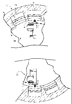
FIGURE 1 is a fragmentary axial cross sectional view of a stator core
illustrating the
wedges, wedge slots and portions of a wedge removal apparatus according to a
preferred aspect of the present invention;
FIGURE 2 is a fragmentary side elevational view illustrating a wedge, a slide,
a ripple
spring and windings in a stator core slot;
FIGURE 3 is a side elevational view of the wedge removal apparatus hereof;
FIGURE 4 is a cross sectional view taken generally about on line 4-4 in Figure
3;
FIGURE 5 is an enlarged side elevational view of a cutter head illustrating a
saw
blade; and
FIGURE 6 is an end elevational view of the cutter head.
DETAILED DESCRIPTION OF THE INVENTION
Refernng now to the drawings, particularly to Figure 1, there is illustrated a
stator
core generally designated 10 forming part of an electrical machine such as an
electrical generator. The stator core 10 has a plurality of longitudinally
extending
slots 12 spaced circumferentially one from the other and opening in a radial
inward
direction. Windings 14 are disposed in the slots 12. As illustrated in Figures
1 and 2,
the radially inwardly opening slots 12 are closed by wedges 16 which have
tapered
surfaces 18 for cooperation with complementary tapered surfaces along the
length of
the slots adjacent the radially inner opening of the slots to retain the
windings within
the slots 12. The undersurfaces of the wedges 16 are tapered as illustrated in
Figure 2
and tapered slides 20 underlie the wedges 16 to maintain the wedges 16 in the
tapered
or dovetail shaped groove of the slots. Ripple springs 22 underlie the slides
20 and lie
between the slides 20 and the windings 14. The ripple springs 22 compress the
slides
and wedges radially inwardly with substantial force. When refurbishing the
electrical
machine, for example, providing rewinding, the wedges 16 are required to be
3
(51 EM) 135296
CA 02512781 2005-07-21
removed. It will be appreciated that substantial radial inward force, e.g., on
the order
of 3500 pounds, is applied to the wedging system, rendering the wedges
difficult to
remove, particularly since saws used to cut the wedges tend to bind up under
the force
of the ripple springs.
A wedge removal assembly is illustrated in Figure 3. The assembly generally
designated 30 includes a substantially rectilinear outer frame 32 which lies
generally
in a single plane. The frame 32 includes longitudinally extending support
members
34 connected to diametrically extending radial elements 36 and 38 forming end
stanchions. The radial elements 36 and 38 are telescopically related to one
another
and are provided with a hydraulic ram arrangement 39 for extending and
retracting
the members 34 diametrically toward and away from the slots of the stator
core.
Outer edges of the longitudinal members 34 at opposite ends of the frame 30
are
provided with pads 40 for bearing against the wedges of diametrically opposed
slots.
It will be appreciated that the frame 30 is disposed longitudinally within the
stator
core with elements 36 and 38 extending diametrically within the core. Upon
actuation
of the hydraulic ram 39, the pads 40 are engaged against the wedges 16 in
diametrically opposed slots.
The frame 30 mounts a carriage assembly generally designated 50 on a linear
drive
assembly generally designated 52. The linear movement assembly 52 includes a
drive
box 54 and an idler box 56 at opposite ends and adjacent opposite ends of the
frame.
The drive box 54 and idler box 56 are pivotally tamed by bearings mounted on
the
end stanchions 36, 38 of the frame 30. Preferably, the linear drive assembly
52 is
mounted for rotation about the stator core axis. Four rails or bars 58 extend
between
the drive and idler boxes 54 and 56, respectively, and the carriage 50 is
slidably
mounted on the bars or rails 58 for axial sliding movement along the bars or
rails
between opposite ends of the linear drive assembly 52.
Referring to Figure 4, the drive box 52 includes an electric motor 60 for
driving a
shaft 62 in corresponding directions. Mounted adjacent opposite ends of shaft
62 are
drive sprockets 64 for driving chains 66. Opposite ends of each chain 66 is
connected
4
(S l EM) 135296
CA 02512781 2005-07-21
to the carriage 50. The chains 66 extend longitudinally about idler sprockets,
not
shown, carried by the idler box 56. Consequently, by energizing motor 60 and
driving shaft 62, the chains 66 translate or drive the carriage SO along the
bars 58 in
selected opposite longitudinal directions.
Carriage 50 mounts a pair of diametrically' opposed cutter heads generally
designated
70 as best illustrated in Figures 5 and 6. The cutter heads 70 include
generally
rectilinear frames 72 mounting a plurality of rollers 74 at radial outer ends.
Rollers 74
straddle a saw blade 76 of a saw 77 as best illustrated in Figure 6, there
being
preferably four rollers on each of the opposite sides of the saw blade 76. The
carriage
50 also includes a hydraulic cylinder 78 (Figure 3) for displacing the cutter
heads 70
radially outwardly and inwardly. Consequently, by actuating the cylinder 78,
the
rollers 74 of the respective heads 70 may engage the wedges in diametrically
opposite
slots of the stator core. As described below, sufficient force is applied by
the cylinder
78 to the rollers and consequently to the diametrically opposed wedges to
compress
the ripple springs underlying the wedges, enabling the saw blade 76 to cut
through the
wedges without binding.
Referring to Figure 4, each saw blade 76, preferably rotary saw 77, is
illustrated in an
extended radially outward cutting position. The saw blade 76 is driven by an
electric
motor 80 mounted on a chassis 82 pivotally coupled at 84 to the rectilinear
frame 72.
An air cylinder 86 adjacent the opposite end of the motor 80 from pivot 84
interconnects the frame 72 and the motor 80 for pivoting the saw blade 76
between a
radial inward non-wedge contacting position and a radial outward sawing
position
vis-a-vis the wedge, the sawing or cutting position being illustrated in both
Figures 5
and 6. The saw blade 76 may be retracted radially inwardly to a position
inwardly of
the rollers 74.
To utilize the wedge removal system hereof, the frame 30 is disposed
longitudinally
within the stator core 10 with the pads 40 aligned with diametrically opposite
wedges
of diametrically opposed stator core slots. The hydraulic cylinders or rams 39
in each
of the stanchions 36, 38 are actuated to engage the diametrically opposed
wedges 16
and secure the frame within the stator core. It will be appreciated that the
frame 30
(51 EM) 135296
CA 02512781 2005-07-21
extends a limited length within the stator core and is repositioned
longitudinally upon
successful completion of cutting the wedges at the location of the wedge
removal
assembly to further longitudinal positions to complete the cutting of the
wedges in
each of the slots.
With the frame 30 fixed within the stator core, the linear drive assembly 52
including
the carriage assembly 50 and heads 70 are rotated into a position aligning the
heads
70 with diametrically opposed wedges in slots circumferentially spaced from
the slots
having wedges engaged by the frame pads 40. For example, as illustrated in
Figure 1,
the linear assembly 52 is rotated to align the heads 70 with wedges
diametrically
opposed adjacent the diametrically opposed wedges engaged by the pads 40. Once
the linear assembly 52 is aligned with the wedges of the adjacent slots, the
hydraulic
cylinder 78 is actuated to displace the heads 70 radially outwardly to engage
the
rollers 74 against the wedges. Sufficient force is applied to the head 70 by
cylinder
78 acting through the rollers 74 to compress the ripple springs 22 underlying
the
wedges 16. With the ripple springs 22 compressed, the electric motors 80 for
the saw
blades 76 are actuated. The air cylinders 86 are also actuated to pivot the
saw blades
76 into engagement with the wedges to cut through central portions thereof in
a
longitudinal direction.
With the saw blades engaged and cutting the wedges, the linear drive assembly
52 is
actuated to draw the carnage 50 and consequently the heads and saw blades 76
Longitudinally along the wedges of the slots whereby the wedges are cut. It
will be
appreciated that by maintaining the wedges under radial outward pressure with
the
ripple springs compressed, the saw blades are able to cut through the wedges
without
the wedges binding the saw blades as would be the case if the ripple springs
were not
compressed. When each saw blade reaches the end of its travel, the air
cylinder 86 is
actuated to withdraw the saw blade from the last wedge cut. Additionally, the
cylinder 78 is actuated to displace the heads 70 in radially inward directions
out of
engagement with the cut wedges. The carriage 50 is then displaced
longitudinally to
its start position along the linear drive assembly by driving the chains 66 in
a reverse
direction. With the heads spaced radially inwardly of the wedges, the linear
drive
assembly 52 is manually rotated about its axis to align the heads 70 with the
next
6
(SIEM)135296
CA 02512781 2005-07-21
circumferentially adjacent slots and wedges. Upon alignment, the cylinder 78
is
actuated to displace the heads 70 radially outwardly to engage and apply
sufficient
forces to the wedges to compress the ripple springs. The previously described
process
is repeated by engaging the saws with the wedges and displacing the carnage 50
along
the drive assembly to cut the wedges. It will be appreciated that the heads 70
and saw
blades are then withdrawn from the cut wedges and the linear drive assembly
displaces the carriage back to the start position for rotation into a further
circumferential position to cut wedges of further circumferentially spaced
slots.
Upon completion of the cutting operations for all circumferentially spaced
slots
except for the slots mounting the frame 32, the hydraulic rams 39 at opposite
ends of
the frame 32 can be retracted to release the frame from the stator core. The
frame is
then rotated to engage diametrically opposed adjacent slots which have been
cut. The
operation is then repeated with the cutting heads 70 aligned with the
remaining two
diametrically opposed uncut wedges of diametrically opposed slots. Once these
slots
have been cut, the wedge removal operation for that length or section of the
stator
core is complete. The frame is then removed from that portion of the stator
core and
advanced longitudinally to another section of the stator core to repeat the
foregoing
described process to cut the wedges of the slots in the next core section.
While the invention has been described in connection with what is presently
considered to be the most practical and preferred embodiment, it is to be
understood
that the invention is not to be limited to the disclosed embodiment, but on
the
contrary, is intended to cover various modifications and equivalent
arrangements
included within the spirit and scope of the appended claims.
7