Language selection

Search

Patent 2512978 Summary

Third-party information liability

Some of the information on this Web page has been provided by external sources. The Government of Canada is not responsible for the accuracy, reliability or currency of the information supplied by external sources. Users wishing to rely upon this information should consult directly with the source of the information. Content provided by external sources is not subject to official languages, privacy and accessibility requirements.

Claims and Abstract availability

Any discrepancies in the text and image of the Claims and Abstract are due to differing posting times. Text of the Claims and Abstract are posted:

  • At the time the application is open to public inspection;
  • At the time of issue of the patent (grant).
(12) Patent: (11) CA 2512978
(54) English Title: MANUALLY CONTROLLED REPLACEMENT SOLENOID FOR HYDRAULIC VALVES
(54) French Title: SOLENOIDE DE REMPLACEMENT A COMMANDE MANUELLE POUR VALVES HYDRAULIQUES
Status: Expired and beyond the Period of Reversal
Bibliographic Data
(51) International Patent Classification (IPC):
  • F16K 31/06 (2006.01)
  • F16K 27/00 (2006.01)
  • H01F 7/06 (2006.01)
(72) Inventors :
  • DELANEY, PATRICK M. (United States of America)
(73) Owners :
  • INTERNATIONAL TRUCK INTELLECTUAL PROPERTY COMPANY, LLC
(71) Applicants :
  • INTERNATIONAL TRUCK INTELLECTUAL PROPERTY COMPANY, LLC (United States of America)
(74) Agent: FINLAYSON & SINGLEHURST
(74) Associate agent:
(45) Issued: 2010-11-16
(22) Filed Date: 2005-07-22
(41) Open to Public Inspection: 2006-02-13
Examination requested: 2010-05-28
Availability of licence: N/A
Dedicated to the Public: N/A
(25) Language of filing: English

Patent Cooperation Treaty (PCT): No

(30) Application Priority Data:
Application No. Country/Territory Date
10/918,782 (United States of America) 2004-08-13

Abstracts

English Abstract

Solenoid controlled hydraulic valves in sealed hydraulic circuits are provided with backup actuation without compromise of the hydraulic circuit by provision of an auxiliary, quick fitting solenoid coil case which incorporates manual switches and which may be attached directly to a battery for energization.


French Abstract

Les valves hydrauliques commandées par solénoïde et faisant partie de circuits hydrauliques fermés sont pourvues de dispositifs de commande de secours afin de ne pas compromettre le fonctionnement du circuit hydraulique. Les dispositifs de secours en question prennent la forme d'un boîtier de solénoïde auxiliaire à installation rapide comportant des interrupteurs manuels et que l'on peut raccorder directement à une pile pour en assurer l'alimentation électrique.

Claims

Note: Claims are shown in the official language in which they were submitted.

WHAT IS CLAIMED IS:
1. Apparatus comprising:
a tube shaped coil case sized and shaped to fit on to a hydraulic valve body
having a
positionally fixed, rod like extension;
a switch carrier mounted onto an outside surface of the tube shaped coil case;
a quick release mechanism mounted through the tube like coil case for locking
the tube
like coil case on the rod like extension for retaining the tube like coil case
on the hydraulic valve
body; and
electrical leads for connection to a battery extending from the switch
carrier.

Description

Note: Descriptions are shown in the official language in which they were submitted.


CA 02512978 2005-07-22
D5544
MANUALLY CONTROLLED REPLACEMENT
SOLENOID FOR HYDRAULIC VALVES
BACKGROUND OF THE INVENTION
1. Technical Field:
The invention relates in general to solenoid control elements for hydraulic
valves and
more particularly to a quick fitting replacement solenoid for use as a
diagnostic tool or
backup actuator for a spool type hydraulic valve in a closed hydraulic
circuit.
2. Description of the Problem:
Vehicle mounted hydraulic systems have been employed for diverse purposes
including
positioning snowplows, compacting trash, moving support beds and other
functions.
Such hydraulic systems are controlled using spool valves and these spool
valves in turn
have often been manually activated, with handles mechanically linked to the
spool
valves. The mechanical link must of course be sealed to avoid spillage of
pressurized
hydraulic fluid. However, these seals are prone to wear and leaks almost
invariably
develop.
To avoid, or at least postpone, the development of leaks, solenoid controlled
hydraulic
valves have been developed. A solenoid coil is used to generate magnetic
fields to
control positioning of the spool valve inside the valve body without the need
for a
mechanical linkage through the valve body. Without a mechanical linkage, the
need for
mechanical seals around a linkage is eliminated. Solenoid actuated valves are
much
less prone to leakage than mechanically actuated valves, but they complicate
making
provision for fitting an override control mechanism to the valve. Some
manufacturer's
have retained a mechanical linkage to use as a backup to the electromagnetic
system.
While the linkages are now used less often, they still represent a compromise
of the full
sealing of the hydraulic system, and they can still develop leaks over time
due to
thermal cycling or chemical attack. The use of solenoids also eases
integration between
1

CA 02512978 2010-06-07
a vehicle's hydraulic systems and the vehicle's electronic control systems.
This in turn
raises questions in some minds as to the reliability of the electronic
controls or the ability
to diagnose a problem as being electronic or hydraulic, should a problem
occur.
SUMMARY OF THE INVENTION
According to the invention there is provided a solenoid coil and valve and
assembly
having an hydraulic valve body having a rod like extension. The solenoid coil
is held
within a tube shaped coil case sized and shaped to fit over and around the rod
like
extension after removal of the original coil assembly. An electrical switch
carrier is
mounted to an outside surface of the tube shaped coil case. Electrical leads
from the
switch body provide for direct, temporary connection to a battery.
More particularly, an embodiment of the invention pertains to an apparatus
comprising a
tube shaped coil case sized and shaped to fit on to a hydraulic valve body
having a
positionally fixed, rod like extension. A switch carrier is mounted onto an
outside surface
of the tube shaped coil case. A quick release mechanism is mounted through the
tube
like coil case for locking the tube like coil case on the rod like extension
for retaining the
tube like coil case on the hydraulic valve body, and electrical leads are
provided for
connection to a battery extending from the switch carrier.
Additional effects, features and advantages will be apparent in the written
description that
follows.
2

CA 02512978 2010-06-07
BRIEF DESCRIPTION OF THE DRAWINGS
The novel features believed characteristic of the invention are set forth in
the appended
claims. The invention itself however, as well as a preferred mode of use,
further aspects
and advantages thereof, will best be understood by reference to the following
detailed
description of an illustrative embodiment when read in conjunction with the
accompanying
drawings, wherein:
Fig. 1 is a perspective view of a prior art solenoid controlled hydraulic
valve assembly.
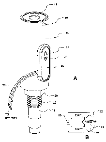
Fig. 2A is a perspective view of an solenoid controlled hydraulic valve
assembly accoding
to the present invention.
Fig. 2B is a circuit schematic for the solenoid controller.
Fig. 3 is an exploded view of a solenoid controller and a hydraulic valve.
2a

CA 02512978 2005-07-22
D5544
Fig. 4 is a partial cross sectional view of the solenoid controlled hydraulic
valve
assembly of Fig. 2.
DETAILED DESCRIPTION OF THE INVENTION
Referring now to the figures and in particular to Fig. 1, a prior art solenoid
controlled
hydraulic valve assembly 10 is shown comprising a hydraulic valve, the stem 12
of
which is visible extending below a coil package 14.
Coil package 14 is substantially self contained, providing only inputs for
connection to
an electronic control system. Coil package 14 provides bi-directional control
of the
valve. Coil package 14 fits over the upper end of valve body 18 and is
retained on
valve body 18 using a nut 16 threaded onto a threaded upper end of valve body
18. A
nut 20 threaded onto the lower a middle threaded section 22 of valve body 18
positions
double ended coil package 14.
Referring to Fig. 2A a replacement solenoid body 24 is a tube like structure,
fitted over
valve body 18 to provide manual control over the valve. Switches 32, 34 are
disposed
on a switch box 26 which in turn is carried on the outside surface of the
replacement
solenoid body 24. Switches 32, 34 provide for manual energization of the
solenoid coil
44. Switch box 26 has electrical leads 28 which are intended for direct
connection to a
12 volt battery, such as the motor vehicle battery or an auxiliary battery. A
quick
release button 30 extends from the replacement solenoid body 24 near the upper
rim of
the solenoid body. The circuit for the solenoid 44 of Fig. 2B may be
represented as a
bridge circuit connected across a battery 60. External buttons 32 and 34
correspond to
switch sets 132 and 134, respectively, which are arranged to energize coil 44
in either
of two directions.
As seen in Fig. 3, replacement solenoid body 24 fits around an upper rod like
segment
42 of valve body 18 and may be fitted with a quick release mechanism released
by
button 30 which cooperates with threads 40 for retaining body 24 on rod 42.
The partial
3

CA 02512978 2005-07-22
D5544
cross section of Fig. 4 better illustrates that replacement valve body 24 is a
tube,
constructed from a casing 46 which contain coils 44 in its interior. Coils 44
are
energized by use of switch box 26. Switch box 26 contains two momentary
switches
used for bi-directional control of the spool valve (not shown) disposed inside
valve body
26. The quick release mechanism 30 extends through casing 46 and cooperates
with
threading 50 at the top end of rod 42.
The invention gives operators the confidence that they can move to electronics
controlled hydraulic systems, with a fully sealed hydraulic system, without
losing the
ability to manually control valves using a direct, simple, electrical system.
Mechanical
backups to electronic solenoid valve control is eliminated.
While the invention is shown in only one of its forms, it is not thus limited
but is
susceptible to various changes and modifications without departing from the
spirit and
scope of the invention.
4

Representative Drawing
A single figure which represents the drawing illustrating the invention.
Administrative Status

2024-08-01:As part of the Next Generation Patents (NGP) transition, the Canadian Patents Database (CPD) now contains a more detailed Event History, which replicates the Event Log of our new back-office solution.

Please note that "Inactive:" events refers to events no longer in use in our new back-office solution.

For a clearer understanding of the status of the application/patent presented on this page, the site Disclaimer , as well as the definitions for Patent , Event History , Maintenance Fee  and Payment History  should be consulted.

Event History

Description Date
Time Limit for Reversal Expired 2015-07-22
Letter Sent 2014-07-22
Grant by Issuance 2010-11-16
Inactive: Cover page published 2010-11-15
Inactive: Final fee received 2010-08-31
Pre-grant 2010-08-31
Notice of Allowance is Issued 2010-07-23
Letter Sent 2010-07-23
Notice of Allowance is Issued 2010-07-23
Inactive: Approved for allowance (AFA) 2010-07-05
Letter Sent 2010-06-08
Advanced Examination Determined Compliant - PPH 2010-06-07
Advanced Examination Requested - PPH 2010-06-07
Amendment Received - Voluntary Amendment 2010-06-07
Request for Examination Requirements Determined Compliant 2010-05-28
All Requirements for Examination Determined Compliant 2010-05-28
Request for Examination Received 2010-05-28
Application Published (Open to Public Inspection) 2006-02-13
Inactive: Cover page published 2006-02-12
Inactive: IPC assigned 2005-09-21
Inactive: First IPC assigned 2005-09-21
Application Received - Regular National 2005-09-01
Filing Requirements Determined Compliant 2005-09-01
Letter Sent 2005-09-01
Inactive: Filing certificate - No RFE (English) 2005-09-01

Abandonment History

There is no abandonment history.

Maintenance Fee

The last payment was received on 2010-06-23

Note : If the full payment has not been received on or before the date indicated, a further fee may be required which may be one of the following

  • the reinstatement fee;
  • the late payment fee; or
  • additional fee to reverse deemed expiry.

Please refer to the CIPO Patent Fees web page to see all current fee amounts.

Owners on Record

Note: Records showing the ownership history in alphabetical order.

Current Owners on Record
INTERNATIONAL TRUCK INTELLECTUAL PROPERTY COMPANY, LLC
Past Owners on Record
PATRICK M. DELANEY
Past Owners that do not appear in the "Owners on Record" listing will appear in other documentation within the application.
Documents

To view selected files, please enter reCAPTCHA code :


To view images, click a link in the Document Description column. To download the documents, select one or more checkboxes in the first column and then click the "Download Selected in PDF format (Zip Archive)" or the "Download Selected as Single PDF" button.

List of published and non-published patent-specific documents on the CPD .

If you have any difficulty accessing content, you can call the Client Service Centre at 1-866-997-1936 or send them an e-mail at CIPO Client Service Centre.


Document
Description 
Date
(yyyy-mm-dd) 
Number of pages   Size of Image (KB) 
Description 2005-07-22 4 161
Abstract 2005-07-22 1 10
Claims 2005-07-22 2 34
Drawings 2005-07-22 4 56
Representative drawing 2006-01-17 1 7
Cover Page 2006-01-24 1 33
Claims 2010-06-07 1 13
Description 2010-06-07 5 171
Cover Page 2010-10-27 1 33
Courtesy - Certificate of registration (related document(s)) 2005-09-01 1 104
Filing Certificate (English) 2005-09-01 1 157
Reminder of maintenance fee due 2007-03-26 1 110
Reminder - Request for Examination 2010-03-23 1 121
Acknowledgement of Request for Examination 2010-06-08 1 192
Commissioner's Notice - Application Found Allowable 2010-07-23 1 164
Maintenance Fee Notice 2014-09-02 1 170
Correspondence 2010-08-31 1 38