Note: Descriptions are shown in the official language in which they were submitted.
CA 02513060 2005-07-08
WO 2004/063620 PCT/GB2004/000094
iONDENSATE TRAP
FIELD OF THE INVENTION
This invention relates to condensate traps.
BACKGROUND OF THE INVENTION
Condensate traps are commonly employed to remove
condensed water from steam utilizing plant and
equipment, in which context they are normally referred
to as steam traps. Many different designs of steam
traps have been developed to suit a variety of
circumstances. The majority of traps involve a self-
actuating mechanism which detects the presence of
condensate in the trap, and when necessary opens to
allow the condensate to drain. These traps have moving
parts and consequently are prone to suffering
mechanical failure. An alternative form of trap is a
fixed orifice trap. These are generally reliable as
they have no moving parts, and in the simplest form
comprise an aperture through which condensate is
discharged. Flash steam produced as the pressure drops
during flow through the aperture acts to reduce the
amount of steam that escapes through the aperture.
One problem encountered with fixed orifice traps is
that the aperture may become blocked. A further problem
is that it is difficult to select an orifice size which
matches the condensate load exactly, so that condensate
is discharged while preventing live steam from leaking
through the aperture. In reality fixed orifice traps
tend to be oversized to ensure that condensate is
CA 02513060 2005-07-08
WO 2004/063620 PCT/GB2004/000094
2
effectively removed while the Consequent loss of steam,
when little or no condensate is present, is accepted.
SUMMARY OF THE INVENTION
According to a first aspect of the present invention
there is provided a condensate trap comprising a vortex
chamber, an inlet being provided far admitting fluid
into the chamber in a manner to promote a rotational
flow of the fluid in the chamber about a longitudinal
axis of the Chamber, and an escape aperture being
provided at an axial end of the chamber.
Preferably at least a portion of the side wall has a
substantially Circular cross section and may be
cylindrical. In one embodiment, the cylindrical portion
adjoins the wider diameter end of a frusto conical
portion. The escape aperture may be provided at the
narrower end of the frusto conical portion, for example
on the longitudinal axis of the chamber.
The chamber may have a circular transverse end wall,
the escape aperture being provided in the centre of the
end wall.
In a practical embodiment of a steam trap in accordance
with the present invention, the vortex chamber may be
provided in a control element supported by a body
provided with inlet and outlet passages which
communicate respectively with the inlet to the chamber
and the escape aperture. The body may be provided with
means for connecting the inlet arid outlet passages to
pipework of a steam utilisation plant.
CA 02513060 2005-07-08
WO 2004/063620 PCT/GB2004/000094
3
The control element and the body may abut each other at
respective contact surfaces, which are preferably flat
and circular. Ports are preferably then provided at
the contact surfaces to provide communication between
the inlet and outlet passages in the body and the
respective inlet and escape aperture in the control
element.
The control element may be engageable with the body at
the contact surfaces in any one of a plurality of
different rotational positions, for example if the
contact surfaces are circular as mentioned above. The
port communicating with the escape aperture may serve
as the centre of rotation between the different
rotational positions. To ensure communication between
the inlet passage and the inlet in all possible
rotational positions, the port communicating with the
inlet may take the form of a circular groove centred on
the port communicating with the escape aperture.
The inlet may be one of a plurality of inlets, for
example three inlets, which are equally distributed
around the chamber and which are directed tangentially
of the chamber to induce the vortex.
The control element may be secured to the body by means
of a cap, which clamps the control element to the
contact surface of the body. The chamber may open at a
face of the control element opposite the contact
surface, in which case the cap preferably closes the
chamber.
A second inlet may be provided, which directs the fluid
towards the central longitudinal axis of the chamber.
CA 02513060 2005-07-08
WO 2004/063620 PCT/GB2004/000094
4
The second inlet may be provided at the same
longitudinal portion along the vortex chamber as the
first inlet. Switch means may be provided to select
either the first or second inlet to introduce the fluid
into the chamber. The switch means may be responsive to
temperature sensing means, such as a bimetallic strip,
which senses the temperature of the fluid upstream of
the trap.
The escape aperture may have any suitable diameter,
depending on the required discharge rate of condensate.
In most circumstances, it is envisaged that the escape
aperture diameter will fall in the range 1 mm to 40 mm,
although in many embodiments the escape aperture
diameter will be less than 30 mm, and possibly less
than 10 mm. For example, the diameter of the escape
aperture may be 5 mm.
According to a second aspect of the present invention,
there is provided a method of reducing a flow of steam
through an escape aperture of a steam trap, comprising
the steps of:
directing a fluid comprising a mixture of steam
and condensate into a chamber in a direction so as to
create a vortex within the chamber, and
providing the escape aperture directly downstream
of a low pressure location within the vortex.
BRIEF DESCRIPTION OF THE DRAWINGS
For a better understanding of the present invention,
and to show more clearly how it may be carried into
effect, reference will now be made, by way of example,
to the accompanying drawings, in which:-
CA 02513060 2005-07-08
WO 2004/063620 PCT/GB2004/000094
Figure 1 is a cross section view of a fixed orifice
steam trap in accordance with a first embodiment of the
present invention;
5 Figure 2 is a plan view of the fixed orifice steam trap
' of Figure 1 as viewed from the line II-II in Figure 1;
Figure 3 is a cross section view of a fixed orifice
steam trap in accordance with a second embodiment of
l0 the present invention;
Figure 4 is a plan view of the fixed orifice steam trap
of Figure 3 as viewed from the line IV-IV in Figure 3;
Figure 5 is a sectioned view of another embodiment of a
steam trap;
Figure 6 is a plan view of the steam trap o'f Figure;
and
Figure 7 is a plan view of a component of the steam
trap of Figures 5 and 6.
DETAILED DESCRIPTION
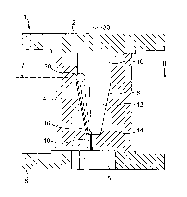
With reference to Figure 1, the steam trap 1 comprises
an upper flange 2, a lower flange 6, and a main body 4
secured between the upper and lower flanges 2,6.
The body 4 defines a vortex chamber 8, having an upper
portion 10 and a lower portion 12. The upper portion 10
of the vortex chamber is cylindrical and closed off at
its upper edge by the upper flange 2. The lower portion
is a conical frustum, continuing from the cylindrical
wall of the upper portion 10 and tapering to a smaller
CA 02513060 2005-07-08
WO 2004/063620 PCT/GB2004/000094
6
diameter at its flat.base 14. An escape aperture 16 is
provided in the centre of the base 14 on the central
axis 30 of the trap l, leading to a conduit 18
extending vertically downwardly from the aperture 16.
The escape aperture 16 is approximately 5 mm diameter
in this example. This communicates at its lower opening
to the surrounding environment or to a condensate
return pipe (not shown), via a circular opening 5 in
the lower flange 6.
The conduit 18 has a length which is greater than the
diameter of the escape aperture, for example greater
than twice the diameter of the escape aperture. In the
embodiment shown, the length of the conduit 18 is 12
mm.
A substantially cylindrical inlet passage 20 is
provided in the main body 4, and opens into the wall of
the chamber 8 at the lower region of the upper portion
10 of the chamber 8. Referring now to Figure 2, the
outermost edge 22 of the cylindrical inlet passage 20
continues tangentially from the cylindrical wall of. the
chamber 8. The innermost edge 24 of the inlet passage
20 is offset from the central axis 30 of the chamber 8
towards the outer edge 22. At the end of the inlet 20
away from the chamber 8, a connector 26 is provided to
connect the inlet 20 to a source of steam and
condensate.
In use, steam and Condensate is introduced tangentially
into the chamber 8 through the inlet 20. With the inlet
20 oriented as shown in Figure 2, the steam and
Condensate flows around the chamber wall 8 in an
anticlockwise direction, creating a vortex. The central
CA 02513060 2005-07-08
WO 2004/063620 PCT/GB2004/000094
7
axis of the vortex lies on or close to the central axis
30 of the chamber 8.
The vortex naturally generates a low pressure at its
centre. As the escape aperture 14 is located on the
central axis 30, the vortex thus provides a low
pressure region directly upstream of the aperture 16.
This reduces the discharge rate through the escape
aperture, and accordingly a larger escape aperture can
be used, reducing the likelihood of the aperture
becoming blocked. Additionally, the self regulatory
mechanisms of the vortex provide increased condensate
discharge in relation to the discharge of steam leaking
from the aperture, as the trap exhibits the following
characteristics:
During plant start up, cold condensate is built up
throughout the system and the condensate load on the
trap is at its highest at this time. As the water is
cold, little or no flash steam will be created, as the
water is typically not near the steam saturation
temperature and so will not flash to steam at the
pressures encountered, either at the low pressure
centre of the vortex, or at pressure of the outside
environment. Therefore the cold water will flow~freely
through the escape aperture 16.
However, as the temperature at the steam trap
increases, the water will eventually reach the
saturation temperature for the pressure prevailing at
the centre of the vortex. At this point vapour or
flash steam will begin to form, and it is this flash
steam that will be expelled through the escape aperture
16. This has the effect of reducing the discharge
CA 02513060 2005-07-08
WO 2004/063620 PCT/GB2004/000094
8
through the escape aperture 16, as the density of the
flash steam is much lower than that of water.
The low pressure created at the centre of the vortex
also reduces the pressure drop from upstream to
downstream of the escape aperture 16. Therefore this
will also reduce the discharge rate of the aperture 16
as an effect additional to the creation of flash steam
as described above.
The flow in the trap is in practice very complex. In
accordance with the present invention the vortex
chamber creates an area of low pressure upstream of the
escape aperture. As is well known in the art, in a
vortex pressure energy is converted to kinetic energy.
From the conservation of energy (Bernoulli) equation,
as the velocity increases the pressure falls.
Therefore, low pressure results in low density at any
given point, in this case the centre of the vortex. By
creating this condition, as steam reaches the escape
orifice, the mass discharge rate is reduced in
accordance with the flow equation for a single phase
f luid
Q = Cd x (~d~ / 4) x '~(p x Op~) where
= flow rate
Cd= discharge coefficient
= orifice diameter
p = fluid density
Op~= critical pressure
drop
CA 02513060 2005-07-08
WO 2004/063620 PCT/GB2004/000094
9
Since the density of water at 20°C is 998 kg/m3 and the
density of steam at 5 barg is 3.2 kg/m3, the ratio of
the mass discharge rates of steam and water is:
py,, 998 - 17. 7
ps 3. 2
Thus, when flash steam is generated just upstream of
the escape aperture 16, the mass discharge rate of the
steam is smaller than that of water by a factor of more
than 17.
In tests, it has been shown that, for a steam line
pressure of 11 bar (ie the pressure at the inlet 20),
the pressure falls to 7 bar at the centre of the
vortex. At 7 bar, the saturation temperature is 165°,
and so if the temperature of the condensate entering
the trap falls below 165°C, no flash steam is generated
and the condensate is discharged. rapidly. Above this
temperature the volume. of flash steam generated will
steadily increase, progressively reducing the rate of
discharge of the escape aperture 16. It has been found
that the mass rate of discharge falls to 50% of its
initial (cold water) value as the condensate
temperature increases from ambient temperature to near
saturation temperature.
Therefore a fixed orifice trap in accordance with the
present invention utilises the Bernoulli effect to
provide a naturally self regulating discharge
characteristic. Cold water is discharged rapidly but
the discharge diminishes rapidly as the saturation
temperature of the fluid is.approached and flash steam
is generated. Once the discharge rate exceeds the
condensate load, some steam is inevitably lost, but the
CA 02513060 2005-07-08
WO 2004/063620 PCT/GB2004/000094
high flow resistance of the vortex minimises this so
that at the extreme where no condensate is present, the
loss is just 50 of the cold water discharge capacity of
the escape aperture. In a more typical application
5 where the hot condensate load is 60% of the capacity of
the discharge escape aperture, the loss will be around
2% of the cold water capacity.
Referring now to Figure 3, a second embodiment of the
10 present invention is shown. Reference numerals in
Figures 3 and 4 relate to similar features as in
Figures 1 and 2.
The steam trap shown in Figures 3 and 4 is provided
with a second inlet 32 which extends radially of the
chamber 8 such that the second inlet 32 directs steam
and condensate into the chamber 8 centrally, towards
the central axis 30 of the chamber 8.
In use, a switching mechanism (not shown) is provided
upstream of the trap 1, either integrally or as a
separate component, and switches the flow between the
first 20 and second 32 inlets. This is controlled by
sensing means which determines the type of fluid in the
pipeline upstream of the trap 1. This may be an
electronic system, or a self actuating system which
responds to temperature, for example employing a
bimetallic element.
If the flow is directed to the first inlet 20, steam
and condensate is introduced tangentially into the
chamber 8 through the inlet 20. The steam and
condensate flows around the chamber wall 8 in an
anticlockwise direction, with reference to Figure 4,
CA 02513060 2005-07-08
WO 2004/063620 PCT/GB2004/000094
11
creating a vortex. The centre of the vortex lies along
the central axis 30 of the chamber 8. As discussed
above, the low pressure volume created by the vortex
upstream of the escape aperture 16 restricts the
discharge through the escape aperture 16.
If the flow is directed to the second inlet 32, as the
inlet 32 is directed towards the central axis of the
chamber 8, no vortex is generated. The trap then acts
as a conventional fixed orifice trap. The pressure
upstream of the escape aperture 16 is higher than with
the vortex, and the aperture is less restricted. In
this way the characteristics of the flow trap can be
altered according to the load. For example, if the
fluid upstream of the inlets is at a low temperature
then it is likely to be all, or nearly all, condensate,
in which case the second inlet 20 may be used thereby
avoiding the creation of a vortex in the chamber 8, and
therefore preventing the associated restriction of the
escape aperture 16 by the generation of flash steam.
This will expel condensate as quickly as possible.
If the fluid upstream of the inlets is predominantly
steam, the first inlet 20 is selected. This creates a
vortex in the chamber and restricts the escape aperture
16 accordingly, therefore reducing the amount of steam
lost to the environment.
In this way, the restriction of the discharge through
the escape aperture can be controlled in response to
the temperature of the fluid entering the trap, and an
improved ratio of condensate to live steam discharge is
achieved.
CA 02513060 2005-07-08
WO 2004/063620 PCT/GB2004/000094
12
Figures 5 to 7 show a practical embodiment of a steam
trap including a vortex chamber 8. The chamber 8 is
secured to a body 40 by a cap 42 which is fastened to
the body 40 by bolts 44 (Figure 6). The body 40
comprises an inlet passage 46 and an outlet passage 48
which have aligned threaded bores 50, 52 for connection
to further pipework. The passages 46, 48 extend to
respective ports 54, 56 at a flat, circular contact
surface 58 formed on the body 40.
10-
The chamber 8 is formed in a control element 60 which
is of generally cylindrical form having opposite axial
end faces 62 and 64. The end face 62 constitutes a
contact surface and abuts the contact surface 58 of the
body 40. The chamber 8 opens at the face 64, and the
inlets 20 are formed as grooves in the face 64. As
shown in Figure 7, there are three of the inlets 20
which are equally distributed about the chamber 8 and
are directed transversely of the chamber 8.
The chamber 8 is generally cylindrical over its full
length, although it has a shallow frusto conical end
wall in which the escape aperture 16 is situated. In
alternative embodiments, the frusto conical end wall
may be replaced by a transverse, radially extending end
wall.
Each inlet 20 is connected by a respective passageway
66 to a port 68 in the form of a circular groove. This
groove 68 is centred on a port 70 and the end of the
conduit 18 away from the escape aperture 16. The.
arrangement of the port 70 and the groove 68 is. such
that the control element 60 can be placed on the
contact surface 58 in any orientation about the port 70
CA 02513060 2005-07-08
WO 2004/063620 PCT/GB2004/000094
13
while maintaining communication between the inlets 20
and the escape aperture 16 and the respective inlet and
outlet passages 46 and 48 by way of the ports 54 and
56. Seals 72, 74 and 76 are provided to prevent
leakage at the faces 62 and 64.
The cap 42 clamps the control element 60 against the
contact face 58 of the body 40. The cap 42 closes the
chamber 8 and the inlets 20. In operation, steam and
condensate enters the trap as indicated by an arrow 78
and passes through the inlet passage 46 to the inlets
by way of the port 54, a groove 68 and the
passageways 66. As described above with reference to
Figures 1 to 4, flow through the inlet 20 creates a
15 vortex within the chamber 8 which regulates flow
through the escape aperture 16. Condensate and steam
passing through the passage 18 enters the outlet
passage 48 by way of the ports 70 and 56, for discharge
or return to the boiler.
The construction shown in Figure 5 makes it simple to
exchange one control element 60 for another without
disturbing the connection between the body 40 and the
surrounding pipework. Such exchange may be desirable
25~ if, for example, a control element 60 of different
characteristics (for example with an escape aperture 16
of a different diameter), or to replace a worn or
damaged control element 60 for another.