Note: Descriptions are shown in the official language in which they were submitted.
CA 02513329 2005-07-18
WO 2004/064489 PCT/IB2004/000855
- 1 - ,
A CUTTING HEAD FOR A BRUSH CUTTER, EDGE TRIMMER OR
SIMILAR
The present invention concerns in general the
field of devices for cutting plants, such as brush
cutters,. edge trimmers, etc.
In this type ~of .device, one or more cutting
strings, progressively unwound from a reserve. as the
strings wear or in the form of individual strands
replaced when worn, must be firmly locked relative to
the rotary cutting head on which they are mounted.
In this regard, a certain number of techniques
are known for locking the string. ,
One of these technique's relies upon a mobile
locking element of the cam type, which is acted upon by
a spring and/or by the -centrifugal force generated
during the rotation of the head to exert a pressure on
the string, a bearing counter-surface being provided
opposite the locking element to trap the string locally
between the element and the bearing surface. The
documents ~ US-A-4 301 642, US-A-4 335 510 and EP-A-
0 824 854 give examples of these techniques.
To improve the locking effect, it is also known
to provicl.e on the locking element a series of teeth
'capable of a better anchoring with the material
(usually a polyamide) of the string.
Despite these provisions, it~ sometimes happens
that the retention of the string in the head is not
achieved with sufficient effectiveness. In such a case,
traction forces exerted on the string, particularly
when the cutting encounters obstacles or particularly
hard or bushy plants, may cause the string to move
CA 02513329 2005-07-18
WO 2004/064489 PCT/IB2004/000855
- 2 -
relative to the locking device, and possibly (in the
F
case of strands of string) slide out of the head.
In extreme cases, it may even happen, under the
effect of very powerful actions (particularly in the
case of a brush cutter with a string of considerable
section), that the locking cam completely passes
through the hard point offered by the string's
resistance to the compression or the squeezing when the
cam turns, to finally cancel out any locking effect.
The present invention aims to overcome these
limitations of the state of the art and to propose an
improved string lock, which at the same times makes a
strand of string easy to put in place and to remove.
.Another aim of the present invention is to have
a locking mechanism that does not interfere with a
central mounting region of the head, i . a . which can be
easily arranged in the head peripheral region.
Still another aim of the present invention is to
make it possible, as a function of the required
retention forces, to make the locking element cooperate
with the string in a gripping relationship over a
significantly greater length of the string than could
be obtained with a cam.
To this end, the invention proposes a cutting
head for a brush cutter, edge trimmer or similar, of
the type comprising a passageway for a cutting string
and a mobile string locking element suitable for
locking the string in its passageway, characterized in
that the passageway is generally offset from a central
axis of the head and opens at both ends at the
periphery of the head, and in that the locking mobile
element is a one way-locking element, whereby a strand
of string can be readily inserted into the passageway
CA 02513329 2005-07-18
WO 2004/064489 PCT/IB2004/000855
- 3 -
from a first end opening thereof and extracted from the
passageway from the second end opening thereof.
Certain preferred, but non-limitative, aspects
of this cutting head are:
* the mobile locking element is located
between the passageway and the periphery of the head.
* the head comprises a cavity sheltering the
locking element and delimited on one side by the
string passageway and on an opposite side by a
surface oriented at an oblique angle relative to the
direction of the string passageway, while the locking
element comprises both a working face capable of
locking the cutting string and a bearing face
oriented at an oblique angle relative to the working
face and suitable for sliding against the said
obliquely angled surface of the cavity.
* the working face of the locking element is
oriented substantially in one plane.
the locking element is acted upon by a
pushing member.
* the pushing member comprises a pressure
spring.
* the pressure spring acts between one surface
of the cavity situated in the region where the
obliquely angled surface is furthest from the string
passageway and a region opposite the locking element.
* the locking element comprises, in the region
of one extremity on the side of engagement with the
cutting string,'a string guidance cut-away section.
* the locking element comprises on a working
face arrangements for gripping with the string.
* the gripping arrangements comprise teeth.
CA 02513329 2005-07-18
WO 2004/064489 PCT/IB2004/000855
- 4 -
* the gripping arrangements are provided
substantially along the whole extent of the working
face of the locking element.
* the locking element comprises in a working
face a longitudinal slot suitable for at least
partially receiving the cutting string.
* the cutting string presents a rugged
section, and the locking element is suitable for
acting on a ridge of the string.
* the locking element is suitable for moving
in translation in a direction generally transverse to
a radial direction of the head.
The invention also proposes a vegetation cutting
device such as a brush cutter, edge trimmer or similar,
characterized in that it comprises a cutting head as
defined above and a motor suitable for driving said
head in rotation.
Other aspects, aims and advantages of the
present invention will appear more clearly from the
following detailed description of the preferred
embodiments of the latter, given by way of non-
limitative example and made with reference to the
appended drawings in which:
Figures 1 to 3 are three 'views in side elevation
illustrating a cutting head according to one embodiment
of the invention.
Figure 4 is a plan view of a generally disc-
shaped part constituting a portion of a cutting head
according to the invention.
Figure 5 is a profile view of two disc-shaped
parts assembled to form the cutting head.
Figure 6 is a profile view of a generally disc-
shaped intermediate part that can, with two other
CA 02513329 2005-07-18
WO 2004/064489 PCT/IB2004/000855
- 5 -
parts, form another cutting head according to the
invention.
Figure 7 is a profile view of this other cutting
head in the assembled state.
Figure 8 is a schematic plan view of the cutting
head in Figure 7, with four strands of cutting string
mounted in the latter.
Figure 8A shows in perspective a curved bearing
zone defined by the cutting head for one of the
strands.
Figure 9 illustrates a detail of the disc-shaped
part in Figure 4, fitted with a device for locking a
strand of string.
Figure 10 is a view in cross-section along the
line X-X in Figure 9.
Figure 11 is a cross-sectional view of a first
variant of embodiment of the string locking device.
Figure 12 is a view in perspective of a locking
member belonging to the locking device in Figure 11.
Figure 13 is a cross-sectional view of a second
variant of embodiment of the string locking device.
Figure 14 is a cross-sectional view of a third
variant of the string locking device.
Figure 15 is a plan view of a fourth variant of
the string locking device, and
Figure 16 is a view in section along the line
XVI-XVI in Figure 15.
It will be noted as a preliminary matter that,
from one figure to the other, the identical or similar
elements or parts have, wherever possible, been
identified by the same reference marks.
Figures 1 to 3 represent a cutting head for a
brush cutter, edge trimmer and similar according to the
CA 02513329 2005-07-18
WO 2004/064489 PCT/IB2004/000855
- 6 -
invention, globally identified by the reference 100,
suitable for being mounted on the extremity of a drive
shaft 200 provided for the purpose, fixing arrangements
202 (washer, nut, mechanism of indexation in rotation),
as well as a counterplate intended to cooperate with
the said fixing arrangements in a manner completely
conventional in itself.
The cutting head is implemented here by
overlaying and assembling two disc-shaped parts 110a
and 110b concentric with the axis of rotation of the
drive shaft 200 and comprising, on their faces turned
one towards the other, arrrangements for running of
strands of string and for retaining those strands as
will be seen in detail below.
Figure 1 illustrates the cutting head 100 before
assembly to the shaft 200, whereas. Figures 2 and 3
illustrate, respectively in a view with partial cutaway
and a view.in elevation, the cutting head mounted on
the shaft.
With reference now to Figure 4, this shows a
disc-shaped part.110 (possibly one of the parts 110a
and 110b in Figures 1 to 3) contributing to the
implementation of the cutting head. It is provided with
a central orifice 1100 through which the drive shaft
200 can pass.
This part 110 comprises a set of 45° bevels 111,
111' (outer bevels) and 111 " (central bevel)
delimiting internally the portions of the part that are
raised and externally the portions of the part that are
recess. The overall contour of the bevels is here
circular and follows the contour of the disc, set back
at a certain distance from this contour.
CA 02513329 2005-07-18
WO 2004/064489 PCT/IB2004/000855
In particular, two bevels 111, 111 " extend in a
rectilinear and adjacent manner the one to the other to
delimit a first zone 112 of cutting string strand
passageway, this passageway opening onto the outside at
a first opening 113 and a second opening 115, for the
outlet of a strand of a cutting string. The axis A
along which the zone 112 extends is situated a certain
distance, marked D, from the centre C of the disc-
shaped part.
At the opening 113, the radius of curvature of
the bevels is small, it being simply to guide the
strand of string when it is put in place.
At the string outlet 115, the bevel 111"
defines a curved bearing zone 120, connected for
preference without change of slope on the one hand with
the string passageway zone 112 and on the other hand
with the circular peripheral zone formed jointly by the
three bevels. This curved bearing zone 120 supports the
strand of string during cutting, in particular when,
when the cutting head rotates, it encounters obstacles
resisting cutting and causing it to give way (the
direction of rotation of the cutting head being given
by the arrow F). It is important to note here,
according to one aspect of the invention, that, due to
the lateral offset of the string passageway 112 in
relation to the centre C of the part 110, that is in
relation to the axis of rotation of the cutting head,
it is possible to give the curved bearing zone 120 a
radius of curvature which is much greater than that
which could be achieved, as in the prior art, with a
string passageway extending geometrically from the
centre C.
CA 02513329 2005-07-18
WO 2004/064489 PCT/IB2004/000855
_ g _
Specifically, in the case of the prior art,
knowing that the central zone of the cutting head is
necessarily occupied by the shaft, very little room is
available in the axial direction for implementing on
the one hand the locking of the strand of cutting
string, and on the other hand the curved bearing
surface .
On the contrary, due to the arrangement of the
invention, a much greater radius of curvature R can be
envisaged and this can (at least locally) be equal to
or even significantly greater than the distance D.
It will be noted here that the curved bearing
zone may have any curved geometric shape required
(circular, with circular sectors of different radius,
elliptical, parabolic, etc.). It will be understood in
particular that there may be one or more constant radii
of curvature, and/or one radius of curvature varying
continuously.
Due to a less pronounced curvature of the curved
bearing zone, the actions are very considerably reduced
as is the fatigue of the strand of string, because the
material of the latter is much less stressed, and this
is particularly important with modern cutting strings
comprising arrangements (teeth, etc.) intended to
facilitate cutting, and/or arrangements (recesses,
protrusions, etc) intended to reduce noise during
rotation, and/or zones of different materials (filled
polyamides, ete:) intended for example to increase wear
resistance.
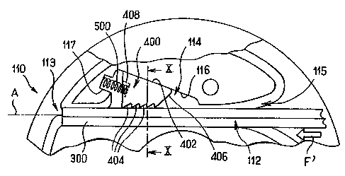
The disc-shaped part 110 also comprises, on a
section of the string strand passageway zone 112, a
cavity 114 intended to receive a string locking shoe
that will be described later. For the moment, mention
D20910PCT
CA 02513329 2005-07-18
WO 2004/064489 PCT/IB2004/000855
- 9
will be made here that this cavity opens out onto the
string passageway zone and comprises on the opposite
side a vertical, unbevelled surface oriented at an
angle relative to the axis A of the string passageway
112, and also comprises, adjacent to the extremity of
the surface 116 furthest away from the axis A, a blind
recess 117 intended for the wedging of a shoe pressure
spring as will be seen in detail later.
Also represented in Figure 4 are holes 118
suitable for being traversed by screws or studs for the
assembly of the part 110 with one or more other disc
shaped parts, designed in similar manner.
Finally, Figure 4 shows that the part 110
comprises, with a symmetry of revolution of 180°
relative to the arrangements described above, some
second passageway, bearing and locking arrangements for
a second strand of string, these arrangements being
indicated by the same reference marks plus a. "prime"
mark.
Figure 5 shows in greater detail a cutting head
implemented by assembling a first disc-shaped part
110a, comprising the arrangements as illustrated in
figure 4, and a second disc-shaped part 110b comprising
corresponding arrangements, with a mirror symmetry,
such that all these arrangements are placed on top of
their counterparts belonging to the other part 110a
during assembly.
It is understood that such an assembly forms
string strand passageways in regular lozenge shape. By
using strands of cutting string of generally square
cross-section and slightly smaller than the cross-
section of the passageways formed in the head, these
passageways retain the strands in an inclination such
D20910PCT
CA 02513329 2005-07-18
WO 2004/064489 PCT/IB2004/000855
- 10
that it is a ridge of each string strand which will
constitute a leading zone for cutting, to thus improve
cutting efficiency.
It will be observed however that such a head may
be used with cutting string strands of any cross
section, provided that they can be engaged without
being trapped in a string passageway.
It is understood that, on the basis of the
arrangements as described with reference to Figure 4,
Figure 5 implements a cutting head with two strings
situated at the same level in vertical direction and
exiting from the head in an oblique direction relative
to a strictly radial direction, in two diametrically
opposed places.
Figure 6 illustrates in elevation another disc-
shaped part 110c, constituting a third intermediate
part of the head.
This part 110c comprises two sets of
arrangements like those represented in Figure 4,
respectively on each of its two faces, with preferably
a mutual offset of 90°. One of these sets of
arrangements forms counterpart arrangements of those of
the part 110a, whereas the other of these sets of
arrangements forms counterpart arrangements of those of
the part 110b. As a corollary, to fit the intermediate
part 110c, the arrangements of the party 110a and 110b
are mutually offset at a 90° angle.
It is understood that, in this way, a cutting
head is implemented comprising an upper level with two
string strands with diametrically opposed outlets, and
a lower level with two other string strands with
diametrically opposed outlets also, but offset by 90°
in relation to the first ones.
CA 02513329 2005-07-18
WO 2004/064489 PCT/IB2004/000855
- 11
This cutting head is illustrated in elevation in
Figure 7. Shown in this figure are two openings,
respectively 113ac and 113cb, offset at an angle of 90°
and belonging respectively to the two levels, the
openings for the outlet of the strings not having been
represented in this figure.
It has been observed that such an arrangement of
strings, with two levels, advantageously provided
chopping of the cut plant material when the distance
between the planes of the string levels was well
chosen. More particularly, and still with reference to
Figure 7, it has been observed that, if the distance H2
between the respective planes Pab and Pbc of the two
string levels is equal to or greater than approximately
1._8 times the height H1 of a string (corresponding
substantially to the height of its passageway), and
preferably equal to or less than approximately 5 times
this same height H1, then particularly satisfactory
chopping is obtained. For example, with a string of
square cross-section with a side length of 4 mm, that
is a diagonal measuring approximately 5.6 mm, the
height offset between the two cutting planes is greater
than approximately 10 mm.
In such a configuration, chopping is equally
favoured if, as described above, the string outlets are
offset at an angle to one another. For preference, and
as also described, this offset is such that, in
circumferential direction, the string outlets are
regularly spaced.
However, irregularly spaced string outlets
(which is obtained in particular if the angular offset
between the arrangements of the upper level and those
CA 02513329 2005-07-18
WO 2004/064489 PCT/IB2004/000855
- 12
of the lower level is not 90°), a satisfactory result
is also obtained.
Figure 8 represents a schematic view from above
of the cutting head in Figure 7. Installed in this
cutting head are three strands of string 300 which
project at the string outlet 115 and which stop
substantially at the openings 113. Also represented in
this figure are the curved bearing surfaces 120 for the
strands of string. The direction of rotation of the
head is illustrated by the arrow F.
In addition, it is understood in the light of
the foregoing that by using two intermediate parts of
the type of part 110c, or more, and two terminal parts
110a and 110, a head can be implemented with any number
of levels.
For example, by using an intermediate part that
has its upper and lower arrangements mutually offset by
60°, and by providing two of such intermediate parts
between the upper and lower parts 110a, 110b, a three-
level cutting head is implemented with string outlets
regularly distributed in a circumferential direction.
Figure 8A illustrates in perspective the curved
bearing surface 120 formed. by the head for one
individual strand of string 300, represented by a part
of its length.
It is understood that such a curved bearing
surface is formed by the curved bearing zones 120a,
120b of the two adjacent disc-shaped parts 110a and
110b (in the case of a version such as the one in
Figure 5), which in turn belong to the 45° bevels 111"
of the respective parts.
This curved bearing surface therefore presents a
V-shaped profile with a 90° bottom angle, that is a
D20910PCT
CA 02513329 2005-07-18
WO 2004/064489 PCT/IB2004/000855
- 13
profile suited to the cross-section of the string 300
at the outlet of its passageway. Such a bearing surface
is therefore used to retain the string in its optimal
cutting orientation at all times, and in particular
when, under the effect of resistance from the plants,
it comes to rest against the bearing surface 120.
Naturally, the profile of the curved bearing
surface will be adapted according to the type of cross
section of the string. In this regard, even in the case
of a string of circular cross-section, it can be
envisaged that the string rests on a curved bearing
zone having a recessed circular profile. This minimizes
the fatigue of the string and increases the cutting
efficiency by stabilizing its trajectory in the cutting
plane when it comes to rest against the said zone. In
particular, it avoids wasting kinetic energy in a
direction transverse to the direction of cutt~.ng
(vertical direction in use).
Figures 9 and 10 illustrate the string locking
mechanism, mounted inside a pair of disc-shaped parts
(parts 110a and 110b in the basic form of
implementation with a single cutting level). This
mechanism comprises a shoe 400 placed in a housing
defined by the cavity 114 formed in one of the disc
shaped parts (see Figure 4), here 110a, and by the
counterpart cavity defined in the other disc-shaped
part, here 110b, which is juxtaposed to it.
This shoe 400 possesses a first face possessing
a plurality of teeth 404 extending transversely to the
axis A of the string passageway 112 and intended to
bite into the cutting string 300 engaged in the said
passageway 112, and an opposite face 402 extending at
an oblique angle relative to the abovementioned first
CA 02513329 2005-07-18
WO 2004/064489 PCT/IB2004/000855
- 14 -
face and intended to rest against the rear face of its
housing, defined by the faces 116 of the two disc-
shaped parts.
,A pressure spring 500 acts between a spring seat
defined jointly by the blind recesses 117 of the two
disc-shaped parts, and a recess 400 formed in a
pressure region of the shoe 400, situated in the region
of greatest height of the said shoe.
On the opposite side (front side), the shoe
possesses an inclined section 406 directed at an
oblique angle towards the top from the tooth 404
situated furthest forward.
The cutting strand of string 300, pre-cut to the
required length, is engaged in its passageway 112 from
its outlet opening 115, in the direction of the arrow
F' in Figure 9. Thus, it pushes back the shoe 400
against the (moderate) force of the spring 500, the
shoe thus being able to rise by sliding against the
rear face 116, 116 of its housing by the amount
necessary to let the strand of string pass. The strand
of string is pushed preferably until its left-hand
extremity in Figure 9 reaches the region of the opening
113, as illustrated in this same figure. The operator
can thus ensure that the string has been fully engaged
beyond the locking shoe. It will be noted here that the
inclined front section 406 guides the strand of string
so that it passes correctly under the shoe 400, on the
toothed side.
It is well understood that, as soon as a pulling
force is exerted on the strand of string in the
direction opposite to the arrow F', which. is typically
the case when the device is working, by friction and
impacts against the plants, the shoe 400, which actes
CA 02513329 2005-07-18
WO 2004/064489 PCT/IB2004/000855
- 15 -
as a one-way lock, tends to exert on the strand of
string 300, through its teeth 404, a retention force by
gripping which is all the greater as the pulling force
increases, this being so due to the inclined face 116,
116 of the housing, providing a wedge effect in
cooperation with the face 402 of the shoe.
Particular advantages of such a locking
mechanism with sliding shoe, in particular when
compared with the known mechanisms with toothed cam or
similar, reside on the one hand in that the retention
force exerted on the strand of string by the shoe,
supported extremely firmly and solidly by the rear
surface 116, 116 of the shoe housing 114, 114, can be
extremely strong and on the other hand in that the
extent, according to the length of the string 300, over
which the teeth 404 cooperate with the string, can be
much greater than with a known cam mechanism.
Other advantages are (i) that the strand of
string can be easily inserted into the passageway
through the opening 115 and easily removed from the
passageway through the opposite opening 113, both being
located at the periphery of the head, and (ii) that the
locking mechanism can be placed between the passageway
112 and the periphery of the head, i.e. without
interfering with the central region of the head in
which the arrangements (recess for shaft and nut) for
mounting the head on the cutting device are to be
positioned.
In the embodiment in Figures 9 and 10, and as is
shown in Figure 10, the teeth 404 retaining the strand
of string extend in a rectilinear manner in a direction
transverse to the string.
CA 02513329 2005-07-18
WO 2004/064489 PCT/IB2004/000855
- 16 -
According to another advantageous aspect, it can
be envisaged that the string strand locking element
(moreover whether it is a sliding shoe, a pivoting cam,
or any other gripping element), is shaped in a manner
to improve the retention of the string.
Thus, while in Figures 9 and 10 the cooperation
between the teeth 404 and the string occurs simply at
the level of the string ridge situated opposite the
shoe, it is envisaged, as illustrated in Figures 11 and
12, that the teeth adopt a profile suited to the shape
of the string. In these figures, there are two series
of teeth 404a, 404b oriented at 90° to one another to
form a profile comprising a recess 403. As a result,
each series of teeth may cooperate with a whole face,
or a substantial part of such a face, of a string in
the case in point of a square cross-section, and the
extent of the cooperation between the shoe and the
string to retain the latter is further increased.
More generally, any recessed profile can be
envisaged at the level of the teeth of the shoe 400 to
better receive the string, irrespective of the shape of
the cross-section of the latter.
Thus Figure 13 illustrates the case in which the
region of the teeth of the shoe 400 has a profile with
a central curved recess, and two series of teeth 404a,
404b of convex profile either side of this recess. In
this case, it is primarily the double row of contact
between the teeth and the string which increases the
gripping force.
It will be observed here that the locking shoes
in Figures 11, 12 and 13 have an improved string
retention efficiency not only with a string of square
cross-section disposed as a lozenge, as described, but
CA 02513329 2005-07-18
WO 2004/064489 PCT/IB2004/000855
- 17 -
also with many other cross-sections of string, and in
particular a circular cross-section.
Figure 14 for its part illustrates the case in
which, with a cutting string 300 of circular cross
section, use is made of a row of teeth 404 having a
convexity suitable for receiving the string, with a
radius of curvature of the string and a radius of
curvature of the profile of the teeth preferably
similar to one another.
It is understood that the use of the string
locking element with a recessed profile zone of contact
with the string applies not only to the case of a shoe,
but also to the case of an element of another type such
as a cam.
Thus Figures 15 and 16 illustrate the locking of
a cutting string 300, in this case of circular cross-
section, with the aid of a cam 400 mounted on a pivot
401 and acted upon by a pressure spring 500. The teeth
404 are disposed on a circular sector eccentric in
relation to the axis of rotation defined by the pivot
401.
It.is observed in this embodiment that the cam
has two rows of teeth 404a, 404b generally straight in
the extension of one another (see Figure 16), these two
rows being separated by a central groove 403. Such a
profile of teeth here further improves the locking of
the string with many shapes of string.
Naturally, the present invention is not limited
to the embodiments described and represented, and those
skilled in the art will be able to provide many
variants and modifications.
Moreover, it is understood that the different
aspects of the new cutting head described in the
CA 02513329 2005-07-18
WO 2004/064489 PCT/IB2004/000855
- 18
foregoing may most frequently be implemented
independently of one another or combined in different
manners.