Note: Descriptions are shown in the official language in which they were submitted.
CA 02513634 2005-07-18
WO 2004/066294 PCT/GB2004/000241
1
THE COPY PROTECTION OF OPTICAL DISCS
The present invention relates to a method of copy protecting optical discs,
to optical discs when so copy protected, and to a data file for enabling
digital
data to be recorded in an encoded and copy protected form on an optical disc.
Optical discs, such as the various formats of compact discs (CDs) and of
digital versatile discs (DVDs) are increasingly used for carrying information
for
many different applications. The information encoded onto the optical discs is
1o generally very valuable and accordingly, they are increasingly copied by
counterfeiters. Furthermore, recordable CDs, and CD writers for writing the
information content from one disc to such recordable discs, are now readily
available to the domestic consumer. Recordable DVDs and DVD writers are
expected to become as readily available in the short term. This means that new
and effective methods for copy protecting optical discs are required.
The present invention seeks to provide new methods of copy protection.
According to a first aspect of the present invention there is provided a
method of copy protecting an optical disc comprising the step of encoding and
recording digital data onto the optical disc in a manner which is arranged to
give
some of the recorded digital data unbalanced dc content.
Preferably, the unbalanced dc content is given to selected areas of the
recorded digital data on the disc.
In the main, players of the information on an optical disc can play the
information recorded thereon despite the unbalanced dc content. However,
readers of the information will experience difficulties in accessing the
information, and, for example, may be caused to jitter. The unbalanced dc
content causes graver problems when attempts are made to copy extracted data
by known "ripping" techniques.
In this respect, in this specification the term "player" is used to refer to
players and drives arranged or controlled to play the data on an optical disc.
This might be, for example, the audio data on a digital audio compact disc
CA 02513634 2005-07-18
WO 2004/066294 PCT/GB2004/000241
2
(CD-DA), or the video data on a digital versatile disc (DVD). Such players
will
include, therefore, commercially available CD music players which function
solely to play the music or other audio on the CD, and commercially available
DVD players which function solely to play the films or other video on the DVD.
It
is generally required that the copy protection methods of the invention do not
generally impinge on the normal operation of such "players".
In this specification the term "data reader" is used to refer to all players
and drives arranged or controlled to read the data on the optical disc, for
1o example, by extracting or ripping the data from the disc. Such,players will
include, therefore, CD-ROM and CD-I drives when configured or controlled to
read or extract audio data from a CD. In this respect, it is required to
enable
drives to play legitimate optical discs, but to prevent them from being used
to
extract the data from the discs or to make usable copies of the discs.
In an embodiment, methods of the invention further comprise
predetermining the selected areas of the recorded digital data which are to be
given unbalanced dc content.
Where the selected areas are predetermined, methods of the invention
may also act to provide for authentication of genuine discs and/or to provide
signatures for discs. In this respect, to establish if a disc is genuine or if
a
signature has been provided, it is necessary only to look to the predetermined
selected areas to see if they contain unbalanced dc content.
In an alternative method of the invention, the method further comprises
randomly selecting the selected areas of the recorded digital data which are
to
be given unbalanced dc content.
In an embodiment, the method may further comprise recording the digital
data onto the optical disc in frames, and providing that each selected area
having unbalanced dc content contains less than 100 frames.
The method may comprise recording the digital data onto the optical disc
in frames arranged into sectors each having a plurality of frames, and
providing
that each selected area having unbalanced dc content contains less than 2
sectors.
CA 02513634 2005-07-18
WO 2004/066294 PCT/GB2004/000241
3
For example, each sector contains 98 frames.
The selected areas which are given unbalanced dc content are preferably
restricted in size such that a player can treat the tracking errors caused
thereby
as burst errors. In this situation, therefore, a player will generally be able
to
continue playing information from the disc without degradation.
In an embodiment, the method further comprises giving some of the
to recorded digital data unbalanced dc content by providing the recorded
digital
data with poor DSV characteristics.
For example, the DSV of the recorded digital data may have a rapid rate
of change.
Additionally and/or alternatively, the DSV of the recorded digital data may
have high absolute values.
Additionally and/or alternatively, the DSV of the recorded digital data may
have substantial low frequency components.
Preferably, the recorded digital data on the optical disc is given
unbalanced dc content by encoding selected areas of the digital data to have
poor DSV characteristics.
According to a further aspect of the invention, there is provided a copy
protected optical disc having encoded digital data recorded thereon, and
wherein some of the digital data recorded on the optical disc has unbalanced
dc
content.
In an embodiment of a copy protected optical disc of the invention,
selected areas of the recorded digital data on the optical disc have
unbalanced
dc content.
In one embodiment, selected areas of the recorded digital data which
have unbalanced dc content have been predetermined.
CA 02513634 2005-07-18
WO 2004/066294 PCT/GB2004/000241
4
In an alternative embodiment, selected areas of the recorded digital data
which have unbalanced dc content have been randomly selected.
Preferably, the size of each said selected area is restricted.
Where the digital data recorded onto the optical disc has been arranged
in frames, each said selected area having unbalanced dc content may contain
less than 100 frames.
io Where the digital data recorded onto the optical disc has been arranged
in sectors with each sector containing a plurality of frames, each said
selected
area having unbalanced dc content may contain less than 2 sectors. Preferably,
each sector contains 98 frames.
In a preferred embodiment, some of the digital data recorded on the
optical disc has been given unbalanced dc content by providing the recorded
digital data with poor DSV characteristics.
For example, the DSV of the recorded digital data may have a rapid rate
of change, and/or high absolute values, and/or substantial low frequency
components.
The present invention is relevant to all formats of optical discs, for
example, the optical disc may be a CD which has been subjected to EFM
encoding, or the optical disc may be a DVD which has been subjected to
EFMPIus encoding.
Similarly, the invention is applicable irrespective of the type of information
carried by the optical disc. For example, the digital data recorded on the
optical
3o disc may be one or more of: audio data, video data, graphics data, visual
data,
animation data, numerical data, program data, control and access data, and/or
any other data.
The invention also extends to a data file enabling digital data to be
encoded and copy protected by a method as defined above.
Such a data file may be arranged to be executable.
CA 02513634 2005-07-18
WO 2004/066294 PCT/GB2004/000241
The present invention also extends to a data file for enabling digital data
to be recorded in an encoded and copy protected form on an optical disc, the
data file having an algorithm for enabling the selection of digital data to be
5 specially encoded, and then for enabling encoding of the selected digital
data
such that it has unbalanced dc content.
A data file of the invention, which may or may not be an executable file, is
intended for use by an encoder for the optical disc. For example, the data
file
1o may be utilised by the encoder of a laser beam recorder during mastering of
an
optical disc.
The encoder is enabled or controlled by the algorithm to select areas of
the digital data for special encoding, and it is this special encoding which
adds
the unbalanced dc content to the master disc.
Where the digital data is to be encoded using EFM encoding with merge
bits chosen during encoding inserted between successive channel bits, the data
file algorithm enables merge bits to be chosen to give poor DSV
characteristics
to the selected digital data.
Where the digital data is to be encoded using EFMPIus encoding where
each 8 bit data word is encoded into one of a choice of four 16 bit channel
words, the data file algorithm enables 16 bit channel words to be chosen to
give
poor DSV characteristics to the selected digital data.
In an embodiment, the algorithm enables selected areas of the digital
data to be chosen for special encoding, each selected area being restricted in
size.
For example, the algorithm determines the number of frames to be
contained within one said selected area of the digital data.
One said selected area may have less than 100 frames.
In an embodiment, the algorithm determines the encoding for each said
selected area of the digital data which would provide good DSV
characteristics,
compares the good DSV value with a predetermined DSV value, and then
CA 02513634 2005-07-18
WO 2004/066294 PCT/GB2004/000241
6
changes the encoding for each said selected area such that the DSV value
approaches the predetermined value whereby poor DSV characteristics are
given to each said selected area.
Embodiments of the present invention will hereinafter be described, by
way of example, with reference to the accompanying drawings, in which:
Figure 1 shows an enlarged view of a CD showing the pits and lands,
Figure 2 shows a section through a pit and land illustrating the data
encoding thereof,
Figure 3 illustrates the DSV corresponding to the encoded data,
Figure 4 shows schematically the manner in which merge bits can be
chosen,
Figure 5 shows schematically the encoding of data onto a CD,
Figure 6 illustrates a frame in the encoded data,
Figure 7 illustrates EFMPlus encoding,
Figure 8 shows schematically part of a spiral track on an optical disc and
its tracking,
Figure 9 illustrates poor DSV characteristics to be encoded onto a disc,
Figure 10 illustrates the effect of poor DSV characteristics, with Figure
1Oa showing the DSV characteristic, Figure 10b showing the associated dc
content, and Figure 1 Oc showing the distortions in audio produced thereby,
and
Figure 11 graphically illustrates the encoding algorithm.
This description specifically explains the encoding of a CD-ROM and the
use of the present invention for copy protecting such a CD-ROM. However, it
will be appreciated that the present invention is not limited to use with a CD-
ROM and finds application to all data carrying optical discs. Specifically,
the
invention is applicable to all formats of CDs and to all formats of DVDs.
Furthermore, the description which follows gives one example of the
encoding of data onto a CD. Other encoding modes are possible and it will be
appreciated that the invention is not limited to the encoding mode.
Figure 1 shows an enlarged view of part of a CD showing the pits 6
thereon. As is well known, these pits extend along a spiral track on the
surface
of the disc and are separated by lands.
CA 02513634 2005-07-18
WO 2004/066294 PCT/GB2004/000241
7
Figure 2 shows a section through a pit 6 and land 8 illustrating how data
is encoded on a CD. The pits and lands do not represent binary Os and 1 s, but
instead represent transitions from one state to another. The data signal is
stored in NRZI form (Non-Return to Zero Inverted), where the signal is
inverted
every time a 1 is encountered. Figure 2 shows the binary value 00100010.
The data stream always consists of pits and lands of at least 3 bits and at
most 11 bits long. This is sometimes referred to as a 3T-1 IT where T is a I
bit
period. A 3T pit has the highest signal frequency (720khz) and an I IT pit has
io the lowest signal frequency (196khz).
A data signal is derived from the lengths of the pits and lands. The
produced signal forms a square wave known as an EFM signal. The digital sum
value (DSV) is the running difference between the number of T values where the
EFM represents a pit and the number of T values where the EFM represents a
land. As each data bit is read, the DSV is incremented or decremented
depending upon whether the data bit corresponds to a pit or a land.
As indicated in Figure 3, the DSV is determined by assigning the value +1
to each land T, and -1 to each pit T. Ideally, the DSV should stray as little
as
possible from the zero level. If the DSV has a rapid rate of change over a
significant period of time or if the DSV has substantial low frequency
components then the transitions in the EFM signal may be shifted from their
ideal values and/or the ability of tracking and focus circuits in CD players
or
drives to maintain optimal head positioning may be compromised. This typically
causes read failures from the CD. This is discussed further below.
Original data, in 8 bit bytes, is passed through a process called EFM
encoding to produce the 14 bit symbols, often referred to as channel bits. The
set of 14 bit symbols is especially designed:
to level out the number of pits and lands, to help maintain balanced DSV;
and
to ensure that there are no symbols which break the EFM coding scheme
of 3T-11 T.
Another way of regarding the 3T,11 T run length limiting rules is that the
number of successive zeros must be greater than two and less than ten. It is
CA 02513634 2005-07-18
WO 2004/066294 PCT/GB2004/000241
8
immediately apparent that this requirement may be compromised where two 14
bit symbols follow one after the other. Accordingly, a set of 3 merge bits are
added between each 14 bit symbol and the one following to ensure that there
are no violations of the 3T-11T coding scheme and to ensure that a suitable
DSV is maintained.
Figure 4 shows schematically the manner in which the merge bits can be
chosen. In Figure 4 there are shown two 8 bit data symbols 30. These are
encoded into two 14 bit channel words 32, for example, by reference to a look
io up table. Then, to ensure that the resultant merged symbols 32 meet the run
length limiting rules, three merge bits XMM are inserted between successive
channel symbols 32.
In the example illustrated in Figure 4, three combinations of merge bits
XMM are possible. Figure 4 shows the transitions for the merged words for
each choice of the merge bits XMM and also shows the DSV associated with
each choice. In the embodiment illustrated, the merge bits 000 give a DSV
value of -1, the merge bits 010 give a DSV value of +7, and the merge bits 001
give a DSV equal to +6. In most cases, therefore, the encoder will choose the
merge bits 000 to give the lowest absolute DSV value.
Figure 5 shows schematically the encoding of data onto a CD in the form
of pits 6 and lands 8. Initially, and as indicated, there are 2048 bytes of
user
data. This is indicated at 10. Then, as illustrated at 12, a sync block, a
header,
an error detection code (EDC) 14 and error correction code (ECC) 16 are added
to those original 2048 bytes.
To help ensure that the final arrangement of pits and lands meet the EFM
coding rules for DSV, the data at 12 is then scrambled as shown at 18 using an
XOR algorithm. The scrambling seeks to reduce the likelihood that plausible
repeating patterns of user data would inadvertently correspond to DSV problem
causing patterns by effectively randomising the data across a sector.
As indicated at 20, the data is then passed to the CIRC encoder. The
CIRC encoder, by means of delays, distributes the data across a number of
sectors. The data is then passed to the EFM encoder 22 where the 8 bit data
words are translated into the 14 bit channel words and the merge bits are
CA 02513634 2005-07-18
WO 2004/066294 PCT/GB2004/000241
9
inserted to form the pattern of 1's and 0's. It is the EFM encoded data which
is
converted into the series of pits and lands on the disc.
As is also known, the encoded data on a CD is arranged in frames. The
format of a frame is illustrated in Figure 6 which shows that each frame has
sync
data, sub-code bits providing control and display symbols, and parity bits
together with data bits. Each frame includes 24 bytes of data, which, for a
CD-DA, for example, is audio data.
There are 8 sub-code bits contained in every frame and designated as P,
Q, R, S, T, U, V and W. Generally only the P and Q sub-code bits are used in
the audio format. The standard requires that 98 of the frames of Figure 6 are
grouped into a sector, and the sub-code bits from the 98 frames are collected
to
form sub-code blocks. That is, each sub-code block is constructed a byte at a
time from 98 successive frames. In this way, 8 different subchannels, P to W,
are formed. These subchannels contain control data for the disc. The P- and
Q- subchannels incorporate timing and navigation data for the tracks on the
disc.
The data encoding on a CD-DA and on a CD-ROM, which is briefly
described above, is well known and in accordance with international standards.
Accordingly, it is not necessary to further describe the encoding, nor the
rules to
which it complies, as both are well known and understood to those skilled in
the
art.
Similarly, the encoding schemes and compliance rules for DVDs are well
known and will not be described in detail herein. In this respect, DVDs do not
use an EFM encoding scheme with merge bits as described above. DVDs use
an encoding scheme known as EFMPIus which is schematically illustrated in
3o Figure 7. In EFMPIus, the 8 bit data words indicated at 30 are translated
into 16
bit channel words, indicated at 32, by way of the EFMPIus modulator 34. This
EFMPIus modulator 34 incorporates a number of look up tables which provide a
choice of four 16 bit words 32' for each input 8 bit word 30'. The algorithm
controlling the modulator 34 manipulates the choice of the 16 bit words 32' to
minimise and control DSV.
CA 02513634 2005-07-18
WO 2004/066294 PCT/GB2004/000241
As set out above, one of the reasons for wishing to keep good DSV
characteristics is that poor DSV characteristics can provide tracking
problems,
for example, in disc readers and players. In this respect, the DSV represents
the dc content of the data signal derived from the pits and lands on the disc.
If
5 that output data signal has a dc offset, tracking problems can occur.
Figure 8 shows schematically part of a spiral track 40 on the surface of an
optical disc and shows a number of pits 6 therein. The pits and lands are to
be
read by one or more lasers (not shown) which have a beam, as 42, which is
1o focused on the track 40. A servo motor is required to maintain precise
alignment between the laser beam 42 and the track 40, and between the laser
beam 42 and the transition boundaries between the pit and land areas. If the
data signal does not have a proper balance of high and low dc, such that the
overall dc content is zero, there is the risk that the servo motor will drift
out of
1s proper alignment with the track 40.
Disc readers and players are provided with appropriate tracking systems
(not shown) to keep the laser beam 42 centred on the track 40. As it plays a
CD-DA, for example, the tracking system has to continually move the laser
outwardly from the centre of the disc towards its periphery. As the laser
moves
outwardly the pits 6 move past the laser beam 42 at an increased and
increasing speed. It will be appreciated that this speed increase occurs
because
the tangential speed of the pits is equal to the radius multiplied by the
speed at
which the disc revolves. Therefore, as the laser moves outwardly, the spindle
motor (not shown) which rotates the disc must slow the speed of the optical
disc.
In this way it is ensured that the pits travel past the laser beam at a
constant
speed and that the data is read from the disc at a constant rate.
It is because the laser tracks the spiral of data using the pits that there
cannot be extended gaps where there are no pits in the data track. This leads
to
the run length limiting rules described above.
Thus, it is generally required to encode data onto a disc such that the
DSV does not have high absolute values, does not change rapidly, and does not
have low frequency components. This latter requirement means that the DSV
does not oscillate in a regular fashion. All these requirements ensure
balanced
dc content. As set out above, a balanced dc content helps the tracking system
CA 02513634 2005-07-18
WO 2004/066294 PCT/GB2004/000241
11
of a reader or player to keep the laser beam centred on the track during data
read out.
The applicants now, radically, suggest that digital data recorded on an
optical disc should be given an unbalanced dc content, and that the unbalanced
dc content created can be used to provide copy protection for optical discs.
In this respect, and as shown in Figure 9, in one embodiment the DSV
value of the encoded data is changed rapidly in less than 100 frames. In the
1o example shown in Figure 9, in less than 100 frames the DSV is changed from
0
to 3000 and then back again to 0. It is thought that where the dc content is
unbalanced for less than two sectors, the run length limiting rules are not
compromised so that no timing violations are introduced. It is also thought
that
the value of the DSV can be increased up to 10000 without any such violations
occuring.
As discussed above, the existence of unbalanced dc content would
generally force the servo motor of a player or reader to move out of proper
alignment with the spiral track. However, because the unbalanced dc content is
introduced in selected areas which are restricted in size, the unbalanced dc
content appears to a player or reader as burst errors and is generally well
handled by players. In this respect, audio and video players traditionally
play at
a speed of 1x, which equals a data transfer rate of 176.4 kbytes per second.
Data readers, which may read at a speed of 50x and greater, are much more
susceptible to the existence of unbalanced dc content. A data reader accessing
the copy protected data may experience error messages, data errors and/or
jitter.
However, it is software provided for the purpose of copying or ripping
content from optical discs which is the most susceptible to the unbalanced dc
content. Traditional ripping software, which uses buffering technology to
retrieve
data from a disc, reads the data in a sector for input into a first buffer,
and then
reads the data again in the same sector for input into a second buffer. The
software requires the contents of the two buffers to be the same as a check
that
the data extracted is correct. The loss of tracking caused by the unbalanced
dc
content makes it difficult, as set out above, to reliably extract the data at
all.
However, it is even more difficult for the software to access the same
position on
CA 02513634 2005-07-18
WO 2004/066294 PCT/GB2004/000241
12
two separate occasions and to retrieve the'same data therefrom. It is expected
that such ripping techniques will fail to retrieve the data. Thus, the
unbalanced
dc content acts to copy protect the information stored on the disc.
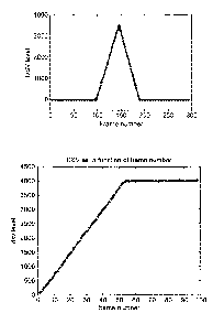
Figure 10 illustrates the problems which a data reader will have when it
tries to read data from an optical disc protected by a method of the
invention. In
Figure 1 Oa there is shown an area of digital data on the optical disc in
which the
DSV has been caused to rise steeply over a limited number of frames. In this
illustration, for example, the DSV rises to 4000 over 53 frames. Figure 10b
1o shows the modified dc content associated with the same area of the disc,
whilst
Figure I Oc shows heavy distortions in audio arising during an attempt to copy
an
audio track which has the single segment of unbalanced dc content as
illustrated
in Figure 10a.
The size, nature and frequency of occurrence of the areas of unbalanced
dc content applied to an optical disc can be chosen as required. Currently it
is
proposed to introduce unbalanced dc content in the form of rapidly increasing
DSV or as an oscillating DSV pattern. The unbalanced dc content may be
applied to the optical disc alone or in addition to other copy protection or
identification techniques.
The unbalanced dc content may also be used in an authentication or
signature technique. - In this respect, it will be known where the unbalanced
content has been located on a disc. A disc can then be checked to ensure that
there is unbalanced data content at a particular location either to
authenticate a
disc or to control its use.
Furthermore, it is possible to apply the unbalanced dc content to localised
areas only of an optical disc to protect data in those localised areas from
3o access.
As set out above, for a CD the value of the merge bits is chosen by the
encoder, for example, of a laser beam recorder, to minimise the DSV on a
master disc. One method of adding unbalanced dc content to an optical disc,
therefore, is to require the encoder to introduce a specific combination of
merge
bits at particular locations on the optical disc during mastering. This can be
done, for example, by the following encoding algorithm:
CA 02513634 2011-11-21
WO 2004/066294 PCT/GB2004/000241
13
1. Determine the length in frames of the segment where unbalanced dc
content will be created.
2. Determine the desired DSV pattern by creating a one-dimensional vector
which stores the values of DSV required after each frame in the segment.
The length of this vector is equal to the number of frames in the segment.
3. For each frame in the segment
3.1 For each EFM symbol in the frame (14 channel bits):
3.1.1. Read the following EFM symbol.
3.1.2. Determine the legal combinations of merge bits between
current and following EFM symbols.
3.1.3. For each legal combination of merge bits:
3.1.3.1. Calculate the DSV value which occurs after the
following EFM symbol.
3.1.3.2. Calculate the difference between the desired DSV
value predetermined for the particular frame. and
that calculated in 3.1.3.1.
3.1.4. Choose the combination of merge bits which minimises the
value calculated in 3.1.3.2.
3.1.5. If more than one such combination of merge bits exists,
choose one that results in an EFM signal transition (pit-land,
or land-pit).
3.2 Encode the frame using the merge bit combinations calculated
in 3.1.
This algorithm is shown graphically in Figure 11 in which the DSV pattern
50 desired for a sequence of frames 52 is indicated. As shown, the DSV is
caused to increase at a rapid rate. The DSV at the end of one frame 54 would
be 250 or lower under normal encoding but, by way of the algorithm is brought
to
3o be as near to 500 as possible. This process carries on with successive
frames
52 such that the desired DSV profile is achieved.