Note: Descriptions are shown in the official language in which they were submitted.
CA 02513790 2005-07-26
1
Description:
The invention relates to a device for the continuous production of a nonwoven
web from filaments made from a thermoplastic synthetic, with a spinning
nozzle,
a cooling chamber, a stretching unit and a depositing device for depositing
the
filaments to the nonwoven web.
A known device of the type specified above (EP 1 340 843 A1 ), which is the
starting point for this invention, has basically proven to be of value for the
production of a nonwoven web from aerodynamically stretched monofilaments.
Unlike other known devices of this type, the filament speed and the filament
fineness can be surprisingly increased here when producing a nonwoven web.
In this way, higher filament flow rates and filaments with finer titres can be
obtained.
The problem which forms the basis of the invention is to provide a device of
the
type specified at the start whereby, with high filament speed and so high flow
rates, and with high levels of filament fineness, the properties of the
filaments
and so the properties of the resulting nonwoven webs can be variable and
specifically set.
In order to solve this technical problem, the invention proposes a device for
the
continuous production of a nonwoven web made from thermoplastic synthetic
filaments, - with a spinning nozzle, a cooling chamber, a stretching unit and
a
depositing device for depositing the filaments to the nonwoven web,
whereby two or more different polymer fusions can be fed to the spinning
nozzle, and whereby a device for merging the different polymer fusions is
provided, such that bi-component filaments or multi-component filaments exit
from the spinning nozzle openings of the spinning nozzle,
CA 02513790 2005-07-26
2
and whereby the cooling chamber is divided into at least two cooling chamber
sections in which the bi-component filaments or multi-component filaments
come into contact respectively with different convective heat discharge means.
- The term process air means cooling air for cooling the filaments. Within the
framework of the invention, process air with different convective heat
discharge
means means in particular process air with a different temperature and/or with
a
different air humidity.
Within the framework of the invention, the term different polymer fusions
means
in particular fusions of different polymers, for example of two different
polyolefins. Also within the framework of the invention, however, the term
also
basically means different polymer fusion fusions of one and the same polymer
with different properties, for example different molecular weights, molecular
weight distributions and rheological and chemical properties. A device for
merging the different polymer fusions means in particular a distribution unit
or a
distribution plate with the help of which the different polymer fusions are
merged
so that they exit from the spinning nozzle openings as bi-component filaments
or multi-component filaments. - In accordance with a highly favoured
embodiment of the invention, the device in accordance with the invention for
producing bi-component filaments which consist of two different polymers is
provided.
Preferably, the device for merging the different polymer fusions is designed
such that bi-component filaments or multi-component filaments with a side to
side configuration and/or with a core-shell configuration can be produced.
Although both of the aforementioned configurations are favoured, it is
nonetheless within the framework of the invention that, with the device in
accordance with the invention, other configurations of bi-component filaments
or
CA 02513790 2005-07-26
3
multi-component filaments can also be produced, for example so-called
segmented pie filaments or island in the sea filaments.
It is within the framework of the invention that the bi-component filaments or
the
multi-component filaments respectively come into contact with process air of a
different temperature in the at least two cooling chamber sections. The
invention is based upon the knowledge that, with a device in accordance with
the invention which has, as well as the other device components in question,
on
the one hand the device for producing bi-component filaments, and on the other
hand the cooling chamber in accordance with the invention with different
temperatures acting upon these filaments, a surprisingly variable, specific
and
reproducable setting of the filament properties and so of the resulting
nonwoven
webs is possible. The set properties are in particular the strength, in
particular
the tensile strength and/or the extension and/or the flexural stiffness and/or
the
bagginess and/or the suppleness and/or the textile grip and/or the drape
behaviour of the nonwoven webs produced.
Advantageously, at least two cooling chamber sections are provided beneath
the spinning nozzle, arranged vertically over one another, in which the bi-
component filaments or the multi-component filaments respectively come into
contact with process air of a different temperature. Preferably, only two
cooling
chamber sections are arranged vertically over one another. After exiting from
the spinning nozzle openings, the bi-component filaments or the multi-
component filaments then first of all pass through a first, upper cooling
chamber
section, and then through a second, lower cooling chamber section.
The invention is based upon the knowledge that bi-component filaments and
multi-component filaments require different procedural process management
than do monofilaments. The device in accordance with the invention is ideally
suited for this special process management. The different polymers in bi-
CA 02513790 2005-07-26
4
component filaments and multi-component filaments have different rheological
properties and different fusion points, glass transition points, specific heat
capacities and crystallisation speeds. If one brings these polymers in
different
configurations and in different mass ratios together, in order to achieve
required
filament finenesses and required physical filament properties, the process
management must be specially set dependent upon the different compositions.
In connection with this within the framework of the invention, the exit speeds
of
the process air from the cooling chamber sections and the temperature and/or
the air humidity of the process air can be set and is adjustable.
In accordance with a preferred embodiment of the invention, the temperature of
the process air is higher in a first, upper cooling chamber section than the
temperature of the process air in a second, lower cooling chamber section.
Preferably, the temperature of the process air in the first, upper cooling
chamber section is higher than the temperature of the process air in the
second,
lower cooling chamber section when the device is set up to produce bi-
component filaments or multi-component filaments, the components of which
consist exclusively of polyolefins or exclusively of polyolefins and
polyesters.
In accordance with one embodiment of the invention, the temperature of the
process air in the first, upper cooling chamber section is 20 to 45°C,
preferably
22 to 40°C , and ideally 25 to 35°C, and the temperature of the
process air in
the second, lower cooling chamber section is 10 to 30°C, preferably 15
to 25°C,
and ideally 17 to 23°C when the device is set up to produce bi-
component
filaments or multi-component filaments, the components of which consist
exclusively of polyolefins. It is within the framework of the invention that
the
temperature of the process air in the first, upper cooling chamber section is
approximately 35°C, and the temperature of the process air in the
second, lower
cooling chamber section is approximately 20°C. Within the framework of
the
invention, the term polyolefin means in particular polyethylene or
polypropylene.
CA 02513790 2005-07-26
The above temperature ratios are set for example when the device is set up to
produce bi-component filaments which contain as components polypropylene
on the one hand and polyethylene on the other hand. These bi-component
filaments have in particular a side to side configuration or a core-shell
5 configuration.
In accordance with another embodiment of the invention, the temperature of the
process air in the upper cooling chamber section is 50 to 90°C,
preferably 55 to
85°C, and ideally 60 to 80°C, and the temperature of the process
air in the
second, lower cooling chamber section is 10 to 40°C, preferably 15 to
35°C,
and ideally 15 to 25°C when the device is set up to produce bi-
component
filaments or multi-component filaments, the components of which consist on the
one hand of polyolefins, and on the other hand of polyesters. Advantageously,
the temperature in the first, upper cooling chamber section can then be
approximately 70°C, and the temperature of the process air in the
second, lower
cooling chamber section can be approximately 20°C. The above
temperature
ratios are in particular set when the device is set up to produce bi-component
filaments of which one component consists of a polyolefin, and the other
components consist of a polyester. Within the framework of the invention,
polyester above all means polyethylene terephthalate (PET). In accordance
with one embodiment of the invention, the above temperature ratios are set for
producing bi-component filaments of which one component consists of
polyethylene, and of which the other components consist of polyethylene
terephthalate (PET).
In accordance with another preferred embodiment of the invention, the
temperature of the process air in the first, upper cooling chamber section is
lower than the temperature of the process air in the second, lower cooling
chamber section when the device is set up to produce bi-component filaments
or multi-component filaments, the components of which consist exclusively of
CA 02513790 2005-07-26
6
polylactides and polyolefins, or exclusively of polyvinyl alcohols and
polyolefins,
or exclusively of polyvinyl alcohols and polyesters. In particular, these can
be
bi-component filaments of which one component consists of a polylactide, and
of which other components consist of a polyolefin, or of which one component
consists of a polyvinyl alcohol, and of which other components consist of a
polyolefin, or of which one component consists of a polyvinyl alcohol and of
which other components consist of a polyester. Within the framework of the
invention, with these embodiments (in accordance with patent claim 7), the
temperature of the process air in the first, upper cooling chamber section 7
is
max. 25°, preferably 10 to 25°C, and ideally 15 to 25°C,
whereas the process
air in the second, lower cooling chamber section is 15 to 40°C,
preferably 15 to
35°C, and ideally 17 to 25°C, always with the proviso that the
temperature of
the process air in the first, upper cooling chamber section is lower than the
temperature of the process air in the second, lower cooling chamber section.
Moreover, when the device is used to produce bi-component filaments or multi-
component filaments, the components of which consist exclusively of polyvinyl
alcohols and polyolefins, or exclusively of polyvinyl alcohols and polyesters,
these filaments advantageously have a segmented pie configuration. When the
device is used to produce bi-component filaments or multi-component filaments,
the components of which consist exclusively of polylactides and polyolefins,
in
accordance with a preferred embodiment, the filaments have a core-shell
configuration, whereby the lactide component is located in the shell.
In accordance with a particularly preferred embodiment of the invention, the
device is set up such that the exit speed of the process air from the first,
upper
cooling chamber section into the second, lower cooling chamber section is less
than the exit speed of the process air from the second, lower cooling chamber
section into the stretching unit or into the intermediary channel. Within the
framework of the invention here, the exit speed of the process air from the
first,
upper cooling chamber section into the second, lower cooling chamber section
CA 02513790 2005-07-26
7
is 1,0 to 1.6 m/sec, preferably 1.1 to 1.5 m/sec, and ideally 1.2 to 1.4
m/sec.
Furthermore, within the framework of the invention the exit speed of the
process
air from the second, lower cooling chamber section into the stretching unit or
into the intermediary channel is 1.5 to 2.1 m/sec, preferably 1.5 to 2.0
m/sec,
and ideally 1.7 to 1.9 m/sec. Advantageously, the v1/v2 ratio of the exit
speed
v1 of the process air from the first, upper cooling chamber section into the
second, lower cooling chamber section to the exit speed v2 of the process air
from the second, lower cooling chamber section into the stretching unit or
into
the intermediary channel is 0.9 to 0.5, preferably 0.85 to 0.6, and ideally
0.8 to
0.7. - It is basically also within the framework of the invention that the
exit
speed of the process air from the first, upper cooling chamber section into
the
second, lower cooling chamber section is greater than the exit speed of the
process air from the second, lower cooling chamber section into the stretching
unit or into the intermediary channel. In this respect, one embodiment of the
invention is characterised in that the ratio v1/v2 of the exit speed v1 of the
process air from the first, upper cooling chamber section into the second,
lower
cooling chamber section to the exit speed v2 of the process air from the
second,
lower cooling chamber section into the stretching unit or into the
intermediary
channel is 1.3 to 0.5.
In accordance with another embodiment of the invention, the exit speed of the
process air from the first, upper cooling chamber section into the second,
lower
cooling chamber section is greater than the exit speed of the process air from
the second, lower cooling chamber section into the stretching unit or into the
intermediary channel. The ratio v1/v2 of the exit speed v1 to the exit speed
v2
is then advantageously 1.2 to 1.8, preferably 1.3 to 1.7 and ideally 1.4 to
1.6. -
The embodiment described first, whereby the exit speed v1 is less than the
exit
speed v2 has proven to be of particular value. With this embodiment,
particularly fine bi-component filaments and multi-component filaments can be
produced.
CA 02513790 2005-07-26
Advantageously, the air feed cabin located next to the cooling chamber is
divided into at least two cabin sections from which process air of a different
temperature and/or different air humidity can be respectively fed into the
allocated cooling chamber section. The air feed cabin here consists of at
least
two cabin sections arranged vertically over one another. Advantageously, only
two cabin sections are arranged vertically over one another. It is within the
framework of the invention, therefore, that the first and the second cabin
sections are arranged vertically over one another, and the first cabin section
here forms the upper cabin section, and the second cabin section forms the
lower cabin section. Preferably, at least one blower is attached to each cabin
section for feeding process air. It is within the framework of the invention
that
the temperature of each cabin section can be regulated. It is also within the
framework of the invention that the volume flows to the individual cabin
sections
can be regulated to the air flows being fed. By setting the volume flow and
the
temperature, in particular of the upper cabin section, the cooling of the
filaments
can be reduced such that higher filaments speeds are possible, and finer
filaments can be spun.
With units known from the prior art, the air feed cabin is generally referred
to as
a blower cabin. With these units, the filaments or the filament bundle have
air
blown specifically over them. It is within the framework of the invention that
with
the unit in accordance with the invention, no blowing over the filaments or
the
filament bundle takes place. Rather the process air is preferably sucked in by
the filaments or the filament curtain. In other words, the filament bundle
sucks
in the process air which it needs. It is thus within the framework of the
invention
that the cooling chamber corresponds to a passive system where blowing air
over the filaments does not take place, but only a sucking in of process air
from
the cabin sections. A barrier layer of air forms concentrically around the
individual filaments respectively, and due to the structure of these barrier
layers,
CA 02513790 2005-07-26
9
the filaments or the filament bundle sucks in the process air. The barrier
layers
guarantee a sufficient distance between the filaments. Because active blowing
is dispensed with, it can be an effective addition, that the filaments have no
possibilities for deflecting in a troublesome manner, and no troublesome
relative
movements of the filaments in relation to one another take place. - Between
the
cooling chamber and the cabin sections, waver rectifiers are advantageously
provided.
In accordance with a highly favoured embodiment of the invention, the ratio of
the length of the first, upper cooling chamber section to the length of the
second, lower cooling chamber section is 0.15 to 0.6, preferably 0.2 to 0.5,
and
ideally 0.2 to 0.4. The above length ratio applies in particular with a
constant
cross-section or with a constant cross-sectional area of the cooling chamber
sections along the flow direction of the filaments.
Cross-sectional area means here the surface at right angles to the flow
direction
of the filaments. Correspondingly, the values given above for the length
ratios
also apply for the volume ratios of the two cooling chamber sections.
Preferably, the second, lower cooling chamber section is approximately 3 times
as long as or has approximately 3 times the volume of the first, upper cooling
chamber section. The above length ratios and volume ratios have proven to be
of particular value when producing bi-component filaments and multi-
component filaments. With these length ratios and volume ratios, very fine bi-
component filaments and multi-component filaments can be obtained, and in
addition, these ratios mean that the properties of these filaments can be set
very specifically and reproducably.
Due to the division of the cooling chamber, in accordance with the invention,
into cooling chamber sections and the division of the air feed cabin into
cabin
sections, and because of the possibility of feeding air flows with different
CA 02513790 2005-07-26
temperatures and different volume flows, an effective separation or decoupling
of the "spinning, cooling" area from the "stretching, pulling" area can be
achieved. In other words, the influences which pressure changes in the
stretching unit have upon the conditions in the cooling chamber can be largely
5 compensated by the measures taken in accordance with the invention. This
aerodynamic separation is also backed up and facilitated by additional
features
in accordance with the invention, dealt with in the following.
It is within the framework of the invention that the cooling chamber is
positioned
10 a distance away from the nozzle plate of the spinning nozzle, and that the
cooling chamber is advantageously positioned several centimetres below the
nozzle plate. In accordance with a highly favoured embodiment of the
invention, a monomer suction device is located between the nozzle plate and
the air feed cabin. The monomer suction device sucks air out of the filament
formation space directly beneath the nozzle plate, and in this way the gases
exiting next to the polymer filaments can be removed from the unit as
monomers, oligomers, decomposition products and similar. Moreover, with the
monomer suction device, the air flow beneath the nozzle plate can be
controlled. This could not remain stationary otherwise due to the indifferent
ratios. The monomer suction device advantageously has a suction chamber to
which preferably at least one suction blower is attached. Preferably, the
suction
chamber has a first suction slit in its lower section which leads into the
filament
formation space. In accordance with a highly favoured embodiment, the suction
chamber also has in its upper section a second suction slit. By sucking
through
this second suction slit it can be effectively avoided that troublesome
turbulence
in the area between the nozzle plate and the suction chamber forms.
Advantageously, the volume flow sucked out by the monomer suction device
can be regulated.
CA 02513790 2005-07-26
11
It is within the framework of the invention that an intermediary channel is
located between the cooling chamber and the stretching unit, and this
intermediary channel converges in a wedge shape in the vertical section from
the exit from the cooling chamber to the entrance into the pulling channel of
the
stretching unit. Advantageously, the intermediary channel converges in a
wedge shape to the entrance into the pulling channel in the vertical section
to
the entrance width of the pulling channel. Preferably, different gradient
angles
of the intermediary channel can be set. It is within the framework of the
invention that the geometry of the intermediary channel can be changed so that
the air speed can be increased. In this way, undesired relaxations of the
filaments which occur with high temperatures can be avoided.
The invention is based upon the knowledge that the above specified technical
problem can be effectively solved if the measures in accordance with the
invention are implemented. Essential for this solution to the technical
problem
is among other things an aerodynamic separation of the cooling of the
filaments
from the stretching of the filaments which is achieved by implementing the
features described in accordance with the invention. Essential to the
invention
for this is first of all the formation in accordance with the invention of the
cooling
chamber and the air feed cabin, and also the possibility of regulating
different
temperatures and volume flows of the air being fed. The other measures in
accordance with the invention explained above also contribute, however, to the
aerodynamic separation. Within the framework of the invention, it is possible
to
separate and aerodynamically separate the filament cooling from the filament
stretching while maintaining reliable function. Aerodynamic separation here
means that pressure changes in the stretching unit have an effect upon the
conditions in the cooling chamber, but however that the setting possibilities
in
the divided air feed can largely compensate this effect upon the fibres. - In
combination with the aerodynamic separation, and in particular in combination
with the setting possibilities in the cooling chamber, the use of bi-component
CA 02513790 2005-07-26
12
filaments and multi-component filaments takes on particular significance. By a
corresponding choice of components and their properties, very specifically
required filament properties and fleece properties can be set. The high level
of
variability and in particular the reproducability of these setting
possibilities is
considerable and surprising.
It is within the framework of the invention that a repositioning unit with at
least
one diffuser is attached to the stretching unit. Preferably, the relocation
unit or
the diffuser is formed with several stages, preferably two stages. In
accordance
with a highly favoured embodiment of the invention, the repositioning unit
consists of a first diffuser and a second diffuser attached to this.
Preferably, an
ambient air entrance gap is provided between the first and the second
diffuser.
In the first diffuser, there is a reduction of the high air speed required to
stretch
the filaments at the end of the pulling channel. This results in a clear
pressure
recovery. Preferably, the opening angle a is infinitely adjustable in a lower
divergent area of the first diffuser. In addition, the divergent side walls of
the
first diffuser are pivotable. This adjustability of the divergent side walls
can be
symmetrical or asymmetrical in relation to the midplane of the first diffuser.
At
the start of the second diffuser, an ambient air entrance gap is provided. Due
to
the high exit impulse from the first diffuser stage, secondary air is sucked
from
the environment through the ambient air entrance gap. Preferably, the width of
the ambient air entrance gap can be set. The ambient air entrance gap can
preferably be set here such that the volume flow of the secondary air sucked
in
is up to 30 % of the incoming volume flow of the process air. Advantageously,
the second diffuser can have its height adjusted, and this height adjustment
is
preferably infinitely variable. In this way, the distance from the depositing
device and the deposit filter band can be varied. - It should be stressed that
with the repositioning unit in accordance with the invention, one effective
aerodynamic separation between the filament formation area and the depositing
area can be achieved from the two diffusers.
CA 02513790 2005-07-26
13
It is also basically within the framework of the invention that the unit in
accordance with the invention can have a repositioning unit without any air
conveyance components or without any diffusers. The filament/air mix then
exits from the stretching unit and arrives directly at the depositing device
or at
the deposit filter band without any air conveyance components. - Furthermore,
it is also within the framework of the invention that after exiting from the
stretching unit, the filaments are electrostatically effected, and in
addition, are
conveyed either through a static or a dynamic field. The filaments are charged
here so that the filaments are prevented from touching one another.
Advantageously, the filaments are then set in motion by a second electric
field,
and this results in an optimal deposit. Any charge still adhering to the
filaments
is then, for example, discharged from the filaments by a special conductive
deposit filter band and/or by appropriate discharging devices.
It is within the framework of the invention that the depositing device has a
continuously moved deposit filter band for the nonwoven web, and at least one
suction device provided beneath the deposit filter band. The at least one
suction device is preferably in the form of a suction blower. Advantageously,
this is at least a controllable and/or adjustable suction blower. - In
accordance
with a highly favoured embodiment of the invention, at least three suction
areas
are positioned, one behind the other, in the direction of movement of the
deposit
filter band, whereby one main suction area is positioned in the depositing
area
of the nonwoven web, whereby a first suction area is positioned in front of
the
depositing area, and whereby a second suction area is positioned after the
depositing area. The first suction area is therefore positioned in the
production
direction in front of the depositing area or in front of the main suction
area, and
the second suction area is positioned after the depositing area or the main
suction area in the production direction. Advantageously, the main suction
area
is separated from the first suction area and from the second suction area by
CA 02513790 2005-07-26
14
corresponding walls. Preferably, the walls of the main suction area are nozzle-
shaped. It is within the framework of the invention that the suction speed in
the
main suction area is greater than the suction speeds in the first suction area
and in the second suction area.
With the unit in accordance with the invention, in comparison to other units
known from the prior art, the filament speed and the filament fineness can be
considerably increased. Higher filament flow rates and filaments with finer
titres
can also be achieved. It is possible, without any problem, to reduce the titre
to
values significantly below 1. With the unit in accordance with the invention,
very
even, homogeneous nonwoven webs can be produced which are characterised
by a high visual quality. - The subject matter of the invention is moreover
also
a method for producing bi-component and multi-component filaments.
In the following, the invention is described in greater detail using drawings
illustrating just one embodiment given as an example. In a schematic
representation:
Fig. 1 shows a vertical section through a device in accordance with the
invention,
Fig. 2 shows the enlarged section A from the subject matter of fig. 1,
Fig. 3 shows the enlarged section B from the subject matter of fig. 1,
Fig. 4 shows the enlarged section C from the subject matter of fig. 1,
Fig. 5 shows a cross-section through a bi-component filament produced by the
device in accordance with the invention, and
CA 02513790 2005-07-26
Fig. 6 shows the subject matter in accordance with fig. 5 in another
embodiment.
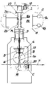
The figures show a device for the continuous production of a nonwoven web
5 from aerodynamically stretched bi-component filaments made from a
thermoplastic synthetic. The device has a spinning nozzle 1 and a cooling
chamber 2 located beneath the spinning nozzle 1, into which the process air
for
cooling the filaments can be fed. An intermediary channel 3 is attached to the
cooling chamber 2. After the intermediary channel 3, there follows a
stretching
10 unit 4 with a pulling channel 5. Attached to the pulling channel 5 there is
a
repositioning unit 6. Beneath the repositioning unit 6 there is a depositing
device in the form of a continuously moved deposit filter band 7 for
depositing
the filaments to the nonwoven web.
15 In accordance with the invention, two different polymer fusions can be fed
to the
spinning nozzle 1 in order to produce bi-component filaments. A non-
illustratable device for merging the two polymer fusions is provided such that
the bi-component filaments exit from the spinning nozzle openings of the
spinning nozzle.
In accordance with a preferred embodiment of the invention, the device in
accordance with the invention is used to produce bi-component filaments with a
side by side arrangement (fig. 5). In accordance with another preferred
embodiment, the device in accordance with the invention is used to produce bi-
component filaments in a core-shell arrangement (fig. 6). In figs. 5 and 6,
the
different polymers of the bi-component filaments were identified by X and Y.
Fig. 2 shows the cooling chamber 2 of the unit in accordance with the
invention,
and also the air feed cabin 8 located next to the cooling chamber 2. In the
embodiment given as an example, the cooling chamber 2 is divided into an
CA 02513790 2005-07-26
16
upper cooling chamber section 2a and a lower cooling chamber section 2b.
Correspondingly, the air feed cabin 8 is divided into an upper cabin section
8a
and a lower cabin section 8b. Process air of a different temperature can be
fed
from both of the cabin sections 8a, 8b. It is within the framework of the
invention that the process air exiting from the upper cabin section 8a has a
higher temperature than the process air exiting from the lower cabin section
8b.
A setting regulation for these temperatures has already been given above.
Moreover, the process air is sucked in by the filaments exiting from the
spinning
nozzle 1 (not illustrated). Advantageously, and in the embodiment given as an
example, a blower 9a, 9b is respectively attached to the cabin sections 8a, 8b
for feeding process air. It is within the framework of the invention here that
the
volume flows of the process air being fed can be regulated. In accordance with
the invention, the temperature of the process air respectively entering into
the
upper cabin section 8a or into the lower cabin section 8b can also be
regulated.
It is within the framework of the invention that the cabin sections 8a, 8b are
located both to the left and to the right of the cooling chamber 2. The left-
hand
halves of the cabin sections 8a, 8b are also attached to the corresponding
blowers 9a, 9b.
Fig. 1 shows that the lower cooling chamber section 2b is three times as long
as
the upper cooling chamber section 2a. Because the cross-section area of the
cooling chamber sections 2a, 2b remains constant in the flow direction of the
filaments, the volume of the lower cooling chamber section 2b is also three
times as great as the volume of the upper cooling chamber section 2a. This
embodiment has proven to be of particular value.
In particular in fig. 2, it can be seen that a monomer suction device 27 is
located
between the nozzle plate 10 of the spinning nozzle 1 and the air feed cabin 8,
and with this, troublesome gases occurring during the spinning process can be
removed from the unit. The monomer suction device 27 has a suction chamber
CA 02513790 2005-07-26
17
28 and a suction blower 29 attached to the suction chamber 28. In the lower
section of the suction chamber 28 a first suction slit 30 is provided. In
accordance with the invention, in the upper section of the suction chamber 28,
a
second suction slit 31 is also located. Advantageously and in the embodiment
given as an example, the second suction slit 31 is narrower than the first
suction
slit 30. With the additional second suction slit 31, troublesome turbulence
between the nozzle plate 10 and the monomer suction device 27 are avoided in
accordance with the invention.
In fig. 1 it can be seen that the intermediary channel 3 from the exit from
the
cooling chamber 2 to the entrance into the pulling channel 5 of the stretching
unit 4 converges in a wedge shape in the vertical section, and advantageously
and in the embodiment given as an example to the entrance width of the pulling
channel 5. In accordance with a highly favoured embodiment of the invention
and in the embodiment given as an example, different gradient angles of the
intermediary channel 3 can be set. Preferably and in the embodiment given as
an example, the pulling channel 5 converges towards the repositioning unit 6
in
a wedge shape in the vertical section. It is within the framework of the
invention
that the channel width of the pulling channel 5 can be set.
In particular in fig. 3 it can be seen that the repositioning unit 6 consists
of a first
diffuser 13 and a second diffuser 14 attached to this, and that an ambient air
entrance gap 15 is provided between the first diffuser 13 and the second
diffuser 14. Fig. 3 shows that each diffuser 13, 14 has an upper, convergent
part as well as a lower divergent part. Consequently, each diffuser 13, 14 has
a
narrowest point between the upper convergent part and the lower divergent
part. In the first diffuser 13 there is a reduction of the high air speeds
required
to stretch the filaments at the end of the stretching unit 4. This results in
a clear
recovery of pressure. The first diffuser 13 has a divergent section 32, the
side
walls 16, 17 of which can be adjusted like flaps. In this way, an opening
angle a
CA 02513790 2005-07-26
18
of the divergent section 32 can be set. This opening angle a is advantageously
between 0.5 and 3°, and is preferably 1 ° or approximately 1
°. The opening
angle a is preferably infinitely variable. The adjustment of the side walls
16, 17
can be both symmetrical and asymmetrical to the midplane M.
At the start of the second diffuser 14, secondary air is sucked in through the
ambient air entrance gap 15 in accordance with the injector principle. Due to
the high exit impulse of the process air from the first diffuser 13, the
secondary
air is sucked from the environment through this ambient air entrance gap 15.
Advantageously, and in the embodiment given as an example, the width of the
ambient air entrance gap 15 can be set. Furthermore, the opening angle f3 of
the second diffuser 14 can preferably be infinitely variable. In addition, the
second diffuser 14 is set up such that the height can be adjusted. In this
way,
the distance a of the second diffuser 14 from the deposit filter band 7 can be
set. By means of the height adjustment of the second diffuser 14 and/or by
means of the pivotability of the side walls 16, 17 in the divergent section 32
of
the first diffuser 13, the width of the ambient air entrance gap 15 can be
set. It
is within the framework of the invention that the ambient air entrance gap 15
is
set so that there is a tangential inflow of the secondary air. Moreover, in
fig. 3
several characteristic dimensions of the repositioning unit 6 are drawn in.
The
distance s2 between the midplane M and a side wall 16, 17 of the first
diffuser
13 is advantageously 0.8 s1 to 2.5 s1 (s1 corresponds here to the distance of
the midplane M from the side wall at the narrowest point of the first diffuser
13).
The distance s3 of the midplane M from the side wall at the narrowest point of
the second diffuser 14 is preferably 0.5 s2 to 2 s2. The distance s4 of the
midplane M from the lower edge of the side wall of the second diffuser 14 is 1
s2 to 10 s2. The length L2 has a value of 1 s2 to 15 s2. Different variable
values are possible for the width of the ambient air entrance gap 15.
CA 02513790 2005-07-26
19
It is within the framework of the invention that the unit comprising the
cooling
chamber 2, the intermediary channel 3, the stretching unit 4 and the
repositioning unit 6 forms a closed system, exclusive of the air suction in
the
cooling chamber 2 and the air entrance gaps on the repositioning unit 6 and
the
air entrance on the ambient air entrance gap 15.
Fig. 4 shows a continuously moved deposit filter band 7 for the nonwoven web
(not shown). Preferably and in the embodiment given as an example, there are
three suction areas 18, 19, 20 positioned behind one another in the direction
of
movement of the deposit filter band 7. A main suction area 19 is provided in
the
depositing area of the nonwoven web. A first suction area 18 is located in
front
of the depositing area or in front of the main suction area 19. A second
suction
area 20 is disposed behind the main suction area 19. A separate suction
blower can basically be allocated to each suction area 18, 19, 20. It is
within
the framework of the invention, however, that only one suction blower is
provided, and that the respective suction conditions are set in the suction
areas
18, 19, 20 with the help of positioning and regulating components. The first
suction area 18 is defined by the walls 21 and 22. The second suction area 20
is defined by the walls 23 and 24. Preferably and in the embodiment given as
an example, the walls 22, 23 of the main suction area 19 form a nozzle
contour.
The suction speed in the main suction area 19 is advantageously higher than
the suction speeds in the first suction area 18 and in the second suction area
20. It is within the framework of the invention that the suction capacity in
the
main suction area 19 is controlled and/or adjusted independently of the
suction
capacities in the first suction area 18 and in the second suction area 20. The
task of the first suction area 18 consists of discharging the quantities of
air fed
by the deposit filter band 7 and to align the flow vectors on the boundary of
the
main suction area 19 orthogonally in relation to the deposit filter band 7.
Moreover, the first suction area 18 serves to hold the filaments already
deposited here on the deposit filter band 7 so that they function reliably. In
the
main suction area 19, the air fed along with the filaments must be able to
flow
CA 02513790 2005-07-26
freely so that the nonwoven web can be deposited reliably. The second suction
area 20, which is disposed behind the main suction area 19, serves to
guarantee the conveyance and to secure the deposited nonwoven web on the
deposit filter band 7. It is within the framework of the invention that at
least one
5 part of the second suction area 20 is located in front of the pressure
mating roll
33 in the conveyance direction of the deposit filter band 7. Advantageously,
at
least one third of the length of the second suction area 20, preferably at
least
half of the length of the second suction area 20 lies in front of the pressure
mating roll 33 in relation to the conveyance direction.