Note: Descriptions are shown in the official language in which they were submitted.
CA 02514317 2005-07-25
WO 2004/073968 PCT/US2004/004427
-1-
PROCESS, COMPOSITION AND COATING OF LAMINATE MATERIAL
RELATED APPLICATIONS
The present application claims priority to United States Patent
Application Serial No. 101366,973, filed February 14, 2003, which is a
Continuation-
In-Part of United States Patent Application Serial No. 10/287,250, filed on
November
4, 2002, which is related to and claims priority to the following U.S.
Provisional
Patent Applications: Serial No. 60/347,858, ftled on November 7, 2001,
entitled
Laminated Panels and Processes; Serial No. 60/349,541, filed on January 18,
2002,
entitled Ti°uss Pafzel; Serial No. 60/358,857, filed on February 22,
2002, entitled
Compressioza Molded Visor; Serial No. 60/359,017, filed on February 22, 2002,
entitled Assemblies and Tooling for Worls Surfaces; Serial No. 60/359,602,
filed on
February 26, 2002, entitled Compression Molded Visor°, and Serial No.
60/400,173,
filed on July 31, 2002, entitled Composite Material. To the extent not
included
below, the subject matter disclosed in these applications is hereby expressly
incorporated into the present application.
TECHNICAL FIELD
The present disclosure relates to fiber boaxds panels, and more
particularly fiber board laminated composites, uses and structures, and
processes of
making the same.
BACKGROUND AND SUMMARY
Industry is consistently moving away from wood and metal structural
members and panels, particularly in the vehicle manufacturing industry. Such
wood
and metal structuxal members and panels have high weight to strength ratios.
In other
words, the higher the strength of the wood and metal structural members and
panels,
the higher the weight. The resulting demand for alternative material
structural
members and panels has, thus, risen proportionately. Because of their low
weight to
strength xatios, as well as their corrosion resistance, such non-metallic
panels have
become particularly useful as structural members in the vehicle manufacturing
industry as well as office structures industry, for example.
Often such non-metallic materials are in the form of composite
structures or panels which are moldable into three-dimensional shapes for use
in any
CA 02514317 2005-07-25
WO 2004/073968 PCT/US2004/004427
-2-
variety of purposes. It would, thus, be beneficial to provide a composite
material
structure that has high strength using oriented and/or non-oriented fibers
with bonding
agents having compatible chemistries to provide a strong bond across the
composite's
layers. It would be further beneficial to provide a manufacturing and finish
coating
process fox such structures in some embodiments.
It will be appreciated that the prior art includes many types of
laminated composite panels and manufacturing processes for the same. U.S.
Patent
Number 4,539,253, fled on March 30, 1984, entitled High Impact Strertgtlt
Fiber
Resin Matrix Composites, U.S. Patent Number 5,141,804, filed on May 22, 1990,
entitled IrtterleafLayer Fiber Reinfor°ced Resin Laminate Composites,
U.S. Patent
Number 6,180,206 B1, filed on September 14, 1998, entitled Corrzposite
Horzeyconzb
Sarzdwiclz Parcel for Fixed Leading Edges, U. S. Patent Number 5,708,925,
filed on
May 10, 1996, entitled Multi-Layered Parzel Having a Core Including Natural
Fibers
and Method ofProducing the Sanze, U.S. Patent Number 4,353,947, filed October
5,
1981, entitledLarninated Composite Str°ucture andMetlzod ofManufacture,
U.S.
Patent Number 5,258,087, filed on March 13, 1992, entitled Method ofMalring a
Composite Structure, U.S. Patent Number 5,503,903, filed on September 16,
I993,
entitled Automotive Headliner Parzel and Method of Malting Same, U.S. Patent
Number 5,141,583, filed on November 14, 199I, entitled Met7tod of and
Apparatus
for Corttirzuously Fabricating Lantirtates, U.S. Patent Number 4,466,847,
filed on
May 6, 1983, entitled Method for the Continuous Production ofLarninates, and
U.S.
Patent Number 5,486,256, fled on May 17, 1994, entitled Method ofMal~irag a
Headliner and the Lilze, are all incorporated herein by reference to establish
the nature
and characteristics of such laminated composite panels and manufacturing
processes
herein.
Accordingly, the following disclosure provides a fibrous moldable
substrate comprising a mat. The mat comprises a fibrous material and a binder.
The
fibers of the fibrous material are randomly oriented. The fibrous material and
binder
is subjected to heat such that only a portion of the binder is wetted to the
fibrous
material.
Illustrative embodiments may provide the fibrous material being hemp
and/or lcenaf; the fibrous material being about 50 weight percent hemp and 50
weight
CA 02514317 2005-07-25
WO 2004/073968 PCT/US2004/004427
-3-
percent kenaf; the mat being about 25 weight percent hemp, about 25 weight
percent
kenaf and about 50 weight percent the binder; the binder being a thermomelt
binder;
the binder being polypropylene; the mat comprises about 24.75 weight percent
hemp,
about 24.75 weight percent kenaf, about 50 weight percent a polypropylene
binder
material and about 0.05 weight percent malefic anhydride; the mat being
subjected to a
compression force where its cross-section is reduced; the mat experiences
insubstantial two-dimensional shrinkage while being subjected to the heat; and
the
fibrous material being selected from a group comprising hemp, kenaf, flax and
jute.
Another embodiment of the disclosure provides a fibrous moldable
substrate also comprising a mat. The mat too comprises a fibrous material and
a
binder. The fibers of the fibrous material are randomly oriented. The fibrous
material
and binder is subjected to heat such that only a portion of the binder is
wetted to the
fibrous material and the binder become dimensionally stable when cooled.
Illustrative embodiments may provide the fibrous material being hemp
and/or kenaf; the fibrous material being about 50 weight percent hemp and 50
weight
percent kenaf; the mat being about 25 weight percent hemp, about 25 weight
percent
kenaf and about 50 weight percent the binder; the binder being a thermomelt
binder;
the binder being polypropylene; the mat comprises about 24.75 weight percent
hemp,
about 24.75 weight percent kenaf, about 50 weight percent a polypropylene
binder
material and about 0.05 weight percent malefic anhydride; the mat being
subjected to a
compression force where its cross-section is reduced; the mat experiencing
insubstantial two-dimensional shrinkage while being subjected to the heat; and
the
fibrous material is selected from a group comprising hemp, kenaf, flax and
jute.
Another embodiment of the disclosure too provides a fibrous moldable
substrate comprising a mat. The mat comprising a fibrous material and a
binder,
wherein fibers of the fibrous material are randomly oriented, and the fibrous
material
and binder is subjected to heat such that only a portion of the binder is
wetted to the
fibrous material;. In addition, the mat is semipermeable when cooled.
Additional features and advantages of this disclosure will become
apparent to those skilled in the art upon consideration of the following
detailed
description of illustrated embodiments exemplifying the best mode of carrying
out
such embodiments as presently perceived.
CA 02514317 2005-07-25
WO 2004/073968 PCT/US2004/004427
-4-
BRIEF DESCRIPTION OF DRAWINGS
The present disclosure will be described hereafter with reference to the
attached drawings which are given as non-limiting examples only, in which:
Fig. 1 is an exploded side view of a laminated hardboard panel;
Fig. 2 is a side view of the laminated hardboard panel of Fig. 1 in an
illustrative-shaped conftguration;
Fig. 3 is a perspective view of a portion of the laminated hardboard
panel of Fig. 1 showing partially-pealed plies of woven and non-woven material
layers;
Fig. 4 is another embodiment of a laminated hardboard panel;
Fig. 5 is another embodiment of a laminated hardboard panel;
Fig. 6 is another embodiment of a laminated hardboard panel;
Fig. 7 is a perspective view of a honeycomb core laminated panel;
Fig. 8 is a top, exploded view of the honeycomb section of the panel of
Fig. 7;
Fig. 9 is a perspective view of a portion of the honeycomb section of
the panel of Fig. 7;
Fig. 10 is a perspective view of a truss core laminated panel;
Fig. 11 a is a side view of an illustrative hinged visor body in the open
position;
Fig. l 1b is a detail view of the hinge portion of the visor body of Fig.
11 a;
Fig. 12a is a side view of an illustrative hinged visor body in the folded
position;
Fig. 12b is a detail view of the hinge portion of the visor body of Fig.
12a;
Fig. 13 is an end view of a die assembly to compression mold a fiber
material body and hinge;
Fig. 14a is a top view of the visor body of Figs. 11 and 12 in the open
position;
Fig. 14b is an illustrative visor attachment rod;
CA 02514317 2005-07-25
WO 2004/073968 PCT/US2004/004427
-5-
Fig. 15 is a perspective view of a wall panel comprising a laminated
panel body;
Fig. 16 is a worlc body;
Fig. 17 is a sectional end view of a portion of the work body of Fig. 16
showing an illustrative connection between first and second portions;
Fig. 18 is a sectional end view of a portion of the work body of Fig. 16
showing another illustrative connection between first and second portions;
Fig. 19 is a sectional end view of a portion of the work body of Fig. 16
showing another illustrative connection between first and second portions;
Fig. 20 is a side view of a hardboard manufacturing line;
Fig. 21 a is a top view of the hardboard manufacturing line of Fig 20;
Fig. 22 is a side view of the uncoiling and mating stages of the
hardboard manufacturing line of Fig. 20;
Fig. 23 is a side view of the pre-heating stage of the hardboard
manufacturing line of Fig. 20;
Fig. 24 is a side view of the heat, press and cooling stages of the
hardboard manufacturing line of Fig. 20;
Fig. 25 is a side view of a laminating station and shear and trim stages
as well as a finishing stage of the hardboard manufacturing line of Fig. 20;
Fig. 26 is a top view of the laminating station and shear and trim stages
as well as the finishing stage of the hardboard manufacturing line of Fig. 20;
Fig. 27 is a side view of a portion of the laminating station stage of the
hardboard manufacturing line of Fig. 20;
Fig. 28 is another top view of the shear and trim stages as well as the
finishing stage of the hardboard manufacturing line of Fig. 20;
Fig. 29 is a top view of another embodiment of a laminated hardboard
manufacturing line;
Fig. 30 is a side view of the calendaring stage of the hardboard
manufacturing line of Fig. 29;
Fig. 31 is a diagrammatic and side view of a portion of a materials
recycling system;
CA 02514317 2005-07-25
WO 2004/073968 PCT/US2004/004427
-6-
Fig. 32 is a side view of a materials recycling system and laminated
hardboard manufacturing line;
Fig. 33 is a top view of the materials recycling system and laminated
hardboard manufacturing line of Figs. 31 and 32;
Fig. 34 is a mechanical properties chart comparing the tensile and
flexural strength of an illustrative laminated hardboard panel with industry
standards;
Fig. 35 is a mechanical properties chart comparing the flexural
modulus of an illustrative laminated hardboard panel with industry standards;
and
Figs. a through c 36 are sectional views of the fibrous material layer
subjected to various amounts of heat and pressure.
Corresponding reference characters indicate corresponding parts
throughout the several views. The exemplification set out herein illustrates
several
embodiments, and such exemplification is not to be construed as limiting the
scope of
this disclosure in any manner.
DETAILED DESCRIPTION OF THE DRAWINGS
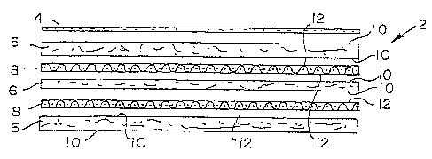
An exploded side view of a laminated composite hardboard panel 2 is
shown in Fig. 1. Hardboard panel 2 illustratively comprises a fascia cover
stock 4
positioned as the surface layer of panel 2. Fascia cover stock 4 may be
comprised of
fabric, vinyl, leathers, acrylic, epoxies, or polymers, etc. It is
appreciated, however,
that hardboard panel 2 may include, or not include, such a fascia cover.
The laminated composite hardboard panel 2 illustratively comprises a
first sheet of fibrous material layer 6. Fibrous material layer 6
illustratively comprises
a natural fiber, illustratively about 25 weight percent hemp and about 25
weight
percent kenaf with the balance being illustratively polypropylene. The fibers
are
randomly oriented to provide a nonspecific orientation of strength. Variations
of this
fibrous material are contemplated including about 24.75 weight percent hemp
and
about 24.75 weight percent lcenaf combination with about 50 weight percent
polypropylene and about 0.05 weight percent malefic anhydride. Other such
fibrous
materials can be used as well, such as flax and jute. It is also contemplated
that other
blend ratios of the fibrous material can be used to provide a nonspecific
orientation of
strength. It is further contemplated that other binders in place of
polypropylene may
CA 02514317 2005-07-25
WO 2004/073968 PCT/US2004/004427
_7_
also be used for the purpose discussed further herein. Furthermore, it is
contemplated
that other fibrous materials which have high process temperatures in excess of
about
400 degrees F, for example, may be used as well.
A woven fiber layer 8 illustratively comprises a woven glass with a
polypropylene binder, and is illustratively located between the fibrous
material layers
6. It is appreciated that other such woven, non-metal fiber materials may be
used in
place of glass, including nylon, Kevlar, fleece and other natural or synthetic
fibers.
Such woven fiber provides bi-directional strength. In contrast, the fibrous
material
layers 6 provide nonspecific-directional strength, thus giving the resulting
composite
enhanced mufti-directional strength.
Each surface 10 of fibrous material layers 6 that is adjacent to woven
material layer 8 bonds to surfaces 12 of layer 8. A bond is created between
fibrous
material layer 6 and woven material layer 8 by a high temperature melt and
pressure
process as discussed further herein. Because the glass and fibrous layers have
compatible binders (i.e., the polypropylene, or comparable binder), layers 6,
8 will
melt and bind, forming an amalgamated bond between the same. Layers 6, 8
having
polypropylene as a common chain in each of their respective chemistries makes
the
layers compatible and amenable to such three-dimensional molding, for example.
It is appreciated that panel 2 may comprise a plurality of fibrous
material layers 6, with woven material layers 8 laminated between each pair of
adjacent surfaces 10 and 12, respectively. A pealed view of hardboard panel 2,
shown
in Fig. 3, illustrates such combined use of woven and nonspecific-directional
or
randomly-oriented fibers. The random fibers 14 make up fibrous material layer
6,
whereas the woven fibers 16 make up the fiber layer 8. Because bulk mass can
increase the strength of the panel, it is contemplated that more alternating
fibrous and
woven fiber layers used in the laminated composite will increase the strength
of the
panel. The number of layers used, and which layers) will be the exterior
layer(s), can
be varied, and is often dictated by the requirements of the particular
application.
Testing was conducted on illustrative hardboard panels to demonstrate
tensile and flexural strength. The hardboard laminated material consisted of a
first
layer of 600 gram 80 percent polypropylene 20 percent polyester fleece, a
second
layer of 650 gram fiberglass mix (75 percent .75 K glass/25 percent
polypropylene
CA 02514317 2005-07-25
WO 2004/073968 PCT/US2004/004427
_g_
and 10 percent malefic anhydride), a third layer 1800 gram 25 percent hemp/25
percent kenaf with 5 percent malefic anhydride and the balance polypropylene,
a
fourth layer of the 650g fiberglass mix, and a fifth layer of the 600g 80
percent
polypropylene 20 percent polyester fleece. This resulted in an approximate
4300
gram total weight hardboard panel.
The final panel was formed by subjecting it to a 392 degrees F oven
with a 6 millimeter gap and heated for about 400 seconds. The material was
then
pressed using a 4.0 millimeter gap. The final composite panel resulted in an
approximate final thickness of 4.30 millimeter.
To determine such panel's tensile and flexural properties, ASTM D
638 - 00 and ASTM D790 - 00 were used as guidelines. The panel samples' shape
and size conformed to the specification outlined in the standards as closely
as
possible, but that the sample thickness varied slightly, as noted above. A
Tinius Olson
Universal testing machine using industry specific fixtures was used to carry
out the
tests.
Two lauan boards were coated with a gelcoat finish and formed into
final 2.7 millimeter and 3.5 millimeter thickness boards, respectively. These
boards
were used as a baseline for comparison with the hardboard panel of the present
disclosure. Each of the samples were then cut to the shape and sizes pursuant
the
above standards. The tensile and flexural properties of the lauan boards were
determined in the same manner as the hardboard panel above. Once the results
were
obtained they were then charted against the results of the hardboard panel for
comparison, as shown below and in Figs. 34 and 35. The results herein
represent the
average over 10 tested samples of each board.
Panel Description Avg. TensileAvg. FlexuralAvg. Flexural
Stren th Stren h - Modulus -
- si psi psi
Hardboard panel 8,585 14,228 524,500
Industry standard - FRPl2.7mm5,883 9,680 1,045,700
lauan
Industry standard - FRP/3.Smm7,900 8,260 624,800
lauan
As depicted by Fig. 2, laminated panel 2 can be formed into any
desired shape by methods known to those skilled in the art. It is appreciated
that the
CA 02514317 2005-07-25
WO 2004/073968 PCT/US2004/004427
_g_
three-dimensional molding characteristics of several fibrous sheets in
combination
with the structural support and strength characteristics of
glass/polypropylene weave
materials located between pairs of the fibrous sheets will produce a laminated
composite material that is highly three-dimensionally moldable while
maintaining
high tensile and flexural strengths. Such a laminated panel is useful for the
molding
of structural wall panel systems, structural automotive parts, highway trailer
side wall
panels (exterior and interior), recreational vehicle side wall panels
(exterior and
interior), automotive and building construction load floors, roof systems,
modular
constructed wall systems, and other such moldable parts. Such a panel may
replace
styrene-based chemical set polymers, metal, tree cut lumber, and other similar
materials. It is believed that such a moldable laminated panel can reduce part
cost,
improve air quality with reduced use of styrene, and reduce part weight. Such
a panel
may also be recyclable, thereby giving the material a presence of
sustainability.
Another embodiment of a hardboard panel 20 is shown in Fig. 4. This
panel 20 comprises a fibrous material layer 6 serving as the core, and is
bounded by
fiberglass layers 22 and fleece layers 24, as shoran. For example, the fibrous
material
layer 6 may comprise the conventional non-oriented fiber/polypropylene mix as
previously discussed, at illustratively 1800 or 2400g weights. The fiberglass
layer
comprises a 50 weight percent polypropylene/about 50 weight percent malefic
anhydride (illustratively 400g/m2) mix. The fleece layer comprises an about 50
weight percent polypropylene/about 50 weight percent polyester (illustratively
300g/m2) mix. The fleece material provides good adhesion with the
polypropylene
and is water-proof at ambient conditions. Furthermore, the polyester is a
compatible
partner with the polypropylene because it has a higher melt temperature than
the
polypropylene. This means the polypropylene can melt and bond with the other
layer
without adversely affecting the polyester. In addition, the malefic anhydride
is an
effective stiffening agent having high tensile and flexural strength which
increases
overall strength of the panel.
It is contemplated that the scope of the invention herein is not limited
only to the aforementioned quantities, weights and ratio mixes of material and
binder.
For example, the fleece layer 24 may comprise an about 80 weight percent
polypropylene/about 20 weight percent polyester (illustratively 600g/m~) mix.
The
CA 02514317 2005-07-25
WO 2004/073968 PCT/US2004/004427
-10-
laminated composite panel 20 shown in Fig. 4 may include, for example, both
fleece
layers 24 comprising the 50/50 polypropylene/polyester mix, or one layer 24
comprising the 50/50 polypropylene/polyester mix, or the 80/20
polypropylene/polyester mix. In addition, same as panel 2, the binder used for
panel
20 can be any suitable binder such as polypropylene, for example.
Another embodiment of a laminated hardboard panel 28 is shown in
Fig. 5. This panel 28 comprises a fibrous material layer 6 serving as the core
which is
bounded by fleece layers 24, as shown. As with panel 20, the fibrous material
layer 6
of panel 28 may comprise the conventional, non-oriented fiber/polypropylene
mix as
previously discussed, at illustratively 1800 or 2400g weights. Each fleece
layer 24
may comprise an about 50 weight percent polypropylene/about 50 weight percent
polyester (illustratively 300g/m2) mix, or may alternatively be an about 80
weight
percent polypropylene/about 20 weight percent polyester (illustratively
600g/m2) mix.
Or, still alternatively, one fleece layer 24 may be the 50/50 mix and the
other fleece
layer 24 may be the 80/20 mix, for example.
Another embodiment of a laminated hardboard panel 30 is shown in
Fig. 6. This panel 30, similar to panel 20 shown in Fig. 4, comprises a
fibrous
material layer 6 serving as the core which is bounded by fiberglass layers 22
and
fleece layers 24. The formulations for and variations of the fleece layer 24,
the
fiberglass layers 22 and the fibrous material layer 6 may comprise the
formulations
described in the embodiment of panel 20 shown in Fig. 4. Laminated panel 30
further
comprises a calendared surface 32, and illustratively, a prime painted or
coated
surface 34. The calendaring process assists in malting a Class A finish for
automobile
bodies. A Class A finish is a finish that can be exposed to weather elements
and still
maintain its aesthetics and quality. For example, an embodiment of the coated
surface
34 contemplated herein is designed to satisfy the General Motors Engineering
standard for exterior paint performance: GM4388M, rev. June 2001. The process
for
applying the painted or coated finish is described with reference to the
calendaring
process further herein below.
Further illustrative embodiment of the present disclosure provides a
moldable panel material, for use as a headliner, for example, comprising the
following
constituents by weight percentage:
CA 02514317 2005-07-25
WO 2004/073968 PCT/US2004/004427
-11-
about 10 weight percent polypropylene fibers consisting
of polypropylene (about 95 weight percent) coupled
with malefic anhydride (about 5 weight percent), though
it is contemplated that other couplers may work as well;
about 15 weight percent kenaf (or similar fibers such as
hemp, flax, jute, etc.) fiber pre-treated with an anti-
fungal/anti-microbial agent containing about 2 weight
percent active ingredient; wherein the fibers may be
pre-treated off line prior to blending;
about 45 weight percent bi-component (about 4 denier)
polyester fiber; wherein the bi-component blend ratio is
about 22.5 weight percent high melt (about 440 degrees
F) polyester and about 22.5 weight percent low melt
polyester (about 240 to about 300 degrees F which is
slightly below full melt temperature of polypropylene to
permit control of polypropylene movement during heat
phase); wherein, alternatively, like fibers of similar
chemistry may also be used; and
about 30 weight percent single component polyester
fiber (about 15 denier) high melt (about 440 degrees F);
wherein, alternatively, like fibers of similar chemistry
may be used.
Again, such a material can be used as a headliner. This is because the
formulation has a higher heat deflection created by stable fibers and high
melt
polypropylene, and by polyester and the cross-linked polymer to the polymer of
the
fibers. Furthermore, coupled polypropylene has cross-linked with non-
compatible
polyester low melt to form a common melt combined polymer demonstrating higher
heat deflection ranges. The anti-fungal treated natural fiber protects any
cellulous in
the fiber from colonizing molds for the life of the product should the head
liner be
exposed to high moisture conditions.
It is appreciated that other formulations can work as well. For
example, another illustrative embodiment may comprise about 40 percent bi-
component fiber with 180 degree C melt temperature, about 25 percent single
component PET-15 denier; about 15 percent 63015 polypropylene and about 20
percent fine grade natural fiber. Another illustrative embodiment may comprise
about
percent bi-component fiber semi-crystalline 170 degree C melt temperature,
about
20 percent single component PET-15 denier, about 15 percent low melt flow (10-
12
CA 02514317 2005-07-25
WO 2004/073968 PCT/US2004/004427
-12-
mfi) polypropylene and about 20 percent fine grade natural fiber. It is
further
contemplated that such compositions disclosed herein may define approximate
boundaries of usable formulation ranges of each of the constituent materials.
A cutaway view of a honeycomb composite panel 40 is shown in Fig.
7. The illustrated embodiment comprises top and bottom panels, 42, 44, with a
honeycomb core 46 located there between. One illustrative embodiment provides
for
a polypropylene honeycomb core sandwiched between two panels made from a
randomly-oriented fibrous material. The fibrous material is illustratively
about 30
weight percent fiber and about 70 weight percent polypropylene. The fiber
material is
illustratively comprised of about 50 weight percent kenaf and about 50 weight
percent
hemp. It is contemplated, however, that any hemp-like fiber, such as flax or
other
cellulose-based fiber, may be used in place of the hemp or the kenaf. In
addition,
such materials can be blended at any other suitable blend ratio to create such
suitable
panels.
In one illustrative embodiment, each panel 42, 44 is heat-compressed
into the honeycomb core 46. The higher polypropylene content used in the
panels
provides for more thermal plastic available for creating a melt bond between
the
panels and the honeycomb core. During the manufacturing of such panels 40, the
heat
is applied to the inner surfaces 48, 50 of panels 42, 44, respectively. The
heat melts
the polypropylene on the surfaces which can then bond to the polypropylene
material
that makes up the honeycomb core. It is appreciated, however, that other
ratios of
fiber to polypropylene or other bonding materials can be used, so long as a
bond can
be created between the panels and the core. In addition, other bonding
materials, such
as an adhesive, can be used in place of polypropylene for either or both the
panels and
the core, so long as the chemistries between the bonding materials between the
panels
and the core are compatible to create a sufficient bond.
A top detail view of the one illustrative embodiment of honeycomb
core 46 is shown in Fig. 8. This illustrative embodiment comprises
individually
formed bonded ribbons 52. Each ribbon 52 is formed in an illustrative
battlement-lilce
shape having alternating merlons 54 and crenellations 56. Each of the corners
58, 60
of each merlon 54 is illustratively thermally-bonded to each corresponding
corner 62,
64, respectively, of each crenellation 56. Such bonds 66 which illustratively
run the
CA 02514317 2005-07-25
WO 2004/073968 PCT/US2004/004427
-13-
length of the corners are shown in Fig. 9. Successive rows of such formed and
bonded ribbons 52 will produce the honeycomb structure, as shown.
Another embodiment of the honeycomb composite panel comprises a
fibrous material honeycomb core in place of the polypropylene honeycomb core.
Illustratively, the fibrous material honeycomb core may comprise about 70
weight
percent polypropylene with about 30 weight percent fiber, for example, similar
to that
used for top and bottom panels 42, 44, previously discussed, or even a 50/50
weight
percent mix. Such formulations are illustrative only, and other formulations
that
produce a high strength board are also contemplated herein.
A perspective view of a truss composite 70 is shown in Fig. 10. Truss
panel composite 70 is a light weight, high strength panel for use in either
two- or
three-dimensional body panel applications. The illustrated embodiment of truss
composite 70 comprises upper and lower layers 72, 74, respectively, which
sandwich
truss member core 76. Each of the layers 72, 74, 76 is made from a combination
fibrous/polypropylene material, similar to that described in foregoing
embodiments.
Each layer 72, 74, 76 comprises a non-directional fibrous material,
illustratively,
about 25 weight percent hemp and about 25 weight percent kenaf with the
balance
being polypropylene. The fibers are randomly oriented to provide a non-
specific
orientation of strength. Illustrative variations of this fibrous material are
contemplated, which may include, for example, an approximately 24.75 weight
percent hemp and 24.75 weight percent kenaf combination with 50 weight percent
polypropylene and 0.05 weight percent malefic anhydride. Other ratios of
fibrous
materials, however, are also contemplated to be within the scope of the
invention. In
addition, other fibrous materials themselves are contemplated to be within the
scope
of the invention. Such materials may be flax, jute, or other like fibers that
can be
blended in various ratios, for example. Additionally, it is appreciated that
other
binders in place of polypropylene may also be used to accomplish the utility
contemplated herein.
The truss core 76 is illustratively formed with a plurality of angled
support portions 78, 80 for beneficial load support and distribution. In the
illustrated
embodiment, support portion 78 is oriented at a shallower angle relative to
upper and
lower layers 72, 74, respectively, than support portion 80 which is oriented
at a
CA 02514317 2005-07-25
WO 2004/073968 PCT/US2004/004427
-14-
steeper angle. It is appreciated that such support portions can be formed by
using a
stamping die, continuous forming tool, or other like method. It is further
appreciated
that the thickness of any of the layers 72, 74, or even the truss core 76 can
be
adjusted to accommodate any variety of load requirements. In addition, the
separation
between layers 72, 74 can also be increased or decreased to affect its load
strength.
Between each support portion is an alternating contact portion, either
82, 84. The exterior surface of each of the alternating contact portions 82,
84 is
configured to bond to one of the inner surfaces 86, 88 of layers 72, 74,
respectively.
To create the bond between layers 72, 74 and truss core 76, superficial
surface heat,
about 450 degrees F for polypropylene, is applied to the contact surfaces to
melt the
surface layer of polypropylene, similar to the process discussed further
herein. At this
temperature, the polypropylene or other binder material is melted sufficiently
to bond
same with the polypropylene of the core. hi this illustrative embodiment,
contact
portion 82 bonds to the surface 86 of upper layer 72, and contact portion 84
bonds to
the surface 88 of layer 74. Once solidified, a complete bond will be formed
without
the need for an additional adhesive. It is appreciated, however, that an
adhesive may
be used in place of surface heat bonding.
The outer surfaces of layers 72, 74 may be configured to accommodate
a fascia cover stock (not shown). Such fascia cover stock may be comprised of
fabric,
vinyl, acrylic, leathers, epoxies, or polymers, paint, etc. In addition, the
surfaces of
layer 72, 74 may be treated with a polyester to waterproof the panel.
An end view of a hinged visor body 90 is shown in Fig. 11 a. This
disclosure illustrates a visor, similar to a sun visor used in an automobile.
It is
appreciated, however, that such a visor body 90 is disclosed herein for
illustrative
purposes, and it is contemplated that the visor does not represent the only
application
of a formed hinged body. It is contemplated that such is applicable to any
other
application that requires an appropriate hinged body.
In the illustrated embodiment, body 90 comprises body portions 92, 94
and a hinge 96 positioned therebetween. (See Figs. l 1b and 12b.) Body 90 is
illustratively made from a low density fibrous material, as further described
herein
below. In one embodiment, the fibrous material may comprise a randomly-
oriented
fiber, illustratively about 50 weight percent fiber-like hemp or kenaf with
about 50
CA 02514317 2005-07-25
WO 2004/073968 PCT/US2004/004427
-15-
weight percent polypropylene. The material is subjected to hot air and to
variable
compression zones to produce the desired structure. (See further, Fig. 13.)
Another
illustrative embodiment comprises about 25 weight percent hemp and about 25
weight
percent kenaf with the balance being polypropylene. Again, all of the fibers
are
randomly oriented to provide a non-specific orientation of strength. Other
variations
of this composition are contemplated including, but not limited to, about a
24.75
weight percent hemp and about a 24.75 weight percent kenaf combination with
about
50 weight percent polypropylene and about 0.05 weight percent malefic
anhydride.
Additionally, other fibrous materials are contemplated to be within the scope
of this
disclosure, such as flax and jute in various ratios, as well as the fibers in
various other
blend ratios. It is also appreciated that other binders in place of
polypropylene may
also be used for the utility discussed herein.
The illustrated embodiment of body 90 comprises hinge portion 96
allowing adjacent body portions 92, 94 to move relative to each other. The
illustrative
embodiment shov~m in Figs. 11 a and b depicts body 90 in the unfolded
position. This
embodiment comprises body portions 92, 94 having a thickness such that hinge
portion 96 is provided adjacent depressions 98, 100 on the surface body
portions 92,
94, respectively. Because body 90 is a unitary body, the flexibility of hinge
portion
96 is derived from forming same into a relatively thin member, as herein
discussed
below. In such folding situations as shown in Fig. 12a, material adjacent the
hinge
may interfere with the body's ability to fold completely. These depressions
98, 100
allow body portions 92, 94 to fold as shown in Fig. 12a, without material from
said
body portions interfering therewith. As shown in Fig. 12b, a cavity 102 is
formed
when body portions 92, 94 are folded completely. It is contemplated, however,
that
such occasions may arise wherein it may not be desired to remove such material
adjacent hinge portion 96, as depicted with depressions 98, 100. Such
instances is
contemplated to be within the scope of this disclosure.
In the illustrative embodiment shown in Fig. 1 1b, hinge portion 96
forms an arcuate path between body portions 92, 94. The radii assists in
removing a
dimple that may occur at the hinge when the hinge is at about 180 degrees of
bend.
As shown in Fig. 12b, hinge portion 96 loses some of its arcuate shape when
the body
portions 92, 94 are in the folded position. It is appreciated, however, that
such a hinge
CA 02514317 2005-07-25
WO 2004/073968 PCT/US2004/004427
-16-
96 is not limited to the arcuate shape shown in Fig. 11 a. Rather, hinge
portion 96 may
be any shape so long as it facilitates relative movement between two
connecting body
portions. For example, hinge portion 96 may be linear shaped. The shape of the
hinge portion may also be influenced by the size and shape of the body
portions, as
well as the desired amount of movement between said body portions.
Illustratively, in addition to, or in lieu of, the fibrous material forming
the visor hinge via high pressure alone, the hinge may also be formed by
having a
band of material removed at the hinge area. In one illustrative embodiment, a
hinge
having a band width about 1/8 inch wide and a removal depth of about 70 weight
percent of thickness mass allows the hinge full compression thickness after
molding
of about 0.03125 inch, for example. The convex molding of the hinge may
straighten
during final folding assembly, providing a straight mid line edge between the
two
final radiuses. It is contemplated that the mold for the mirror depressions,
etc., plus
additional surface molding details can be achieved using this process. It is
further
anticipated that the cover stock may be applied during the molding process
where the
cover is bonded to the visor by the polypropylene contained in the fibrous
material
formulation.
The illustrative embodiment of body 90 includes longitudinally-
extending depressions 93, 95 which form a cavity 97. (See Figs. l la, 12a and
14a.),
Cavity 97 is configured to receive bar 99, as discussed further herein. (See
Fig. 14b.)
It is appreciated that such depressions and cavities described herein with
respect to
body 90 are for illustrative purposes. It is contemplated that any design
requiring
such a moldable body and hinge can be accomplished pursuant the present
disclosure
herein.
As previously discussed, body 90 may be comprised of low density
material to allow variable forming geometry in the visor structure, i.e., high
and low
compression zones for allowing pattern forming. For example, the panels
portion
may be a low compression zone, whereas the hinge portion is a high compression
zone. In addition, the high compression zone may have material removed
illustratively by a saw cut during production, if required, as also previously
discussed.
This allows for a thinner high compression zone which facilitates the ability
for the
material to be flexed back and forth without fatiguing, useful for such a
hinge portion.
CA 02514317 2005-07-25
WO 2004/073968 PCT/US2004/004427
-17-
An end view of a die assembly 110 for compression molding a fiber
material body and hinge is shown in Fig. 13. The form of the die assembly 110
shown is of an illustrative shape. It is contemplated that such a body 90 can
be
formed into any desired shape. In the illustrated embodiment, assembly 110
comprises illustrative press plates 112, 114. Illustratively, dies 116, 118
are attached
to plates 112, 114, respectively. Die 116 is formed to mirror corresponding
portion of
body 90. It is appreciated that because the view of Fig. 13 is an end view,
the dies can
be longitudinally-extending to any desired length. This illustrative
embodiment of die
116 includes surfaces 120, 122 and includes compression zones 124, 126, 128,
130.
Zones 124, 126 are illustratively protrusions that help form the depressions
93, 95,
respectively, of body 90, as shown. (See also Fig. 1 la.) Zones 128, 130 are
illustratively protl-usions that help form the depressions 98, 100,
respectively, of body
90, as shown. (See also Fig. l la.) And zone 132 is illustratively a form
that, in
cooperation with zone 134 of die 118, form hinge portion 96.
This illustrative embodiment of die 118 includes surfaces 136, 138 and
includes compression zones 140, 142, 134. Zones 140, 142 are illustratively
sloped
walls that help form zone 134. (See also Fig. 11 a.) Zone 134 is
illustratively a peak
that, in cooperation with zone 132 creates a high compression zone to form
hinge
portion 96, and, illustratively, depressions 98, 100, if desired. Again, it is
appreciated
that the present pattern of such zones shown is not the only such pattern
contemplated
by this disclosure.
In the illustrated embodiment, body 90, in the illustrative form of a
hinged visor, is folded as that shown in Fig. 12a. It is further contemplated
that
during forming the body may be heated by hot air to bring it up to forming
temperatures. The heating cycle time may be about 32 seconds, and the toll
time after
clamp for cool down will be around 45 to 50 seconds, depending on tool
temperature.
Furthermore, skins, like a fabric skin can be bonded to the visor during this
step.
Another embodiment of the hardboard panel is a low density panel,
illustratively, an approximately 2600 gram panel with about 50 weight percent
fiber-
like hemp, kenaf, or other fiber material with about 50 weight percent
polypropylene.
Such materials are subjected to hot air to produce a light-weight, low density
panel.
The panel material may be needle-punched or have a stretched skin surface
applied
CA 02514317 2005-07-25
WO 2004/073968 PCT/US2004/004427
-18-
thereon for use as a tackable panel, wall board, ceiling tile, or interior
panel-lilce
structure.
A portion of a dry-erase board 150 is shown in Fig. 15. Such a board
150 may comprise a hardboard panel 152 (similar to panel 2) pursuant the
foregoing
description along with a surface coating 154. The surface coating, as that
described
further herein, provides an optimum work surface as a dry-erase board. Surface
coating 154, for example, can be a Class A finish previously described. This
illustrative embodiment includes a frame portion 156 to enhance the aesthetics
of
board 150. One embodiment may comprise a dual-sided board with a low density
tack board on one side and a dry-erase hardboard on the other side.
An illustrative embodiment of a work body in the form of a table top
180, is shown in Fig. 16. The view illustrated therein is a partial cut-away
view
showing the mating of a top 182 to an underside 184. An illustrative pedestal
186
supports table top 180 in a conventional manner. It is appreciated, however,
that the
table top 180 is shown in an exaggerated view relative to pedestal 186 so as
to better
illustrate the relevant detail of the table top 180.
In the illustrated embodiment, the periphery 188 of top 182 is arcuately
formed to create a work surface edging. The top 182 is attached to the
underside 184
via a portion of the periphery 190 of the same mating with the top 182.
Periphery 190
illustratively comprises an arcuate edge portion 192 which is complimentarily
shaped
to the interior surface 194 of periphery 188 of top 182. Adjacent the arcuate
edge
portion 192 is an illustrative stepped portion 196. Stepped portion 196
provides a
notch 198 by extending the underside panel 202 of the underside 184 downward
with
respect to top 182. Notch 198 provides spacing for edge 200 of periphery 188.
Such
an arrangement provides an appearance of a generally flush transition between
top
182 and underside 184. Interior surface 194 of periphery 188 and outer surface
204 of
periphery 190 can be mated and attached via any conventional method. For
example,
the surfaces can be ionize-charged to relax the polypropylene so that an
adhesive can
bond the structures. In addition, a moisture-activated adhesive can be used to
bond
the top 182 with the underside 184.
Detailed views of the mating of top 182 and underside 184 is shown in
Figs. 17 and 18. The conformity between peripheries 188 and 190 are evident
from
CA 02514317 2005-07-25
WO 2004/073968 PCT/US2004/004427
-19-
these views. Such allows sufficient bonding between top 182 and underside 184.
The
generally flush appearance between the transition of top 182 and underside 184
is
evident as well through these views. The variations between illustrative
embodiments
are depicted in Figs. 17 and 18. For example, top surface 206 is substantially
coaxial
with level plane 208 in Fig. 17, whereas top surface 206 is angled with
respect to level
plane 208. It is appreciated, as well, that the disclosure is not intended to
be limited to
the shapes depicted in the drawings. Rather, other complimentarily-shaped
mating
surfaces that produce such a transition between such top and bottom panels are
contemplated to be within the scope of the invention herein.
Such mating of top 182 and underside 184 may produce a cavity 210,
as shown in Figs. 16 through 19. Depending on the application, cavity 210 may
remain empty, or may contain a structure. For example, Fig. 19 shows an end
view of
table top 180 with a truss member core support 76 illustratively located
therein. Truss
member core 76 can be of the type previously described and be attached to the
interior
surfaces 194, 212 via conventional means, such as an adhesive, for example.
Such a
core structure can provide increased strength to table top 180. In fact, such
strength
can expand the uses of the world body to other applications in addition to a
table top.
For example, such can be used as a flooring, or side paneling for a structure
or a
vehicle. It is contemplated that other such cores can be used in place of the
truss
member. For example, a foam core or honeycomb core can be used in place of the
truss.
An illustrative hardboard manufacturing line 300 is shown in Figs. 20
through 28. Line 300 is for manufacturing laminated hardboard panels of the
type
shown in Figs. 1 through 3, and indicated by reference numeral 2, for example.
The
manufacturing process comprises the mating of the several layers of materials,
illustratively layers 6 and 8 (see Fig. 1), heating and pressing said layers
into a single
laminated composite panel, cooling the panel, and then trimming same. In the
illustrative embodiment, line 300 comprises the following primary stages:
uncoiling
and mating 302 (Fig. 22), pre-heating 304 (Fig. 23), heat and press 306 (Fig.
24),
cooling 308 (also Fig. 24), laminating station (Figs. 25 through 28), and
shear and
trim 310 (also Figs. 25 through 28.) A top view of line 300 is shown in Fig.
21. It is
appreciated that the line 300 may be of a width that corresponds to a desired
width of
CA 02514317 2005-07-25
WO 2004/073968 PCT/US2004/004427
-20-
the composite material. Fig. 21 also illustrates the tandem arrangement of
each of the
stages 302, 304, 306, 308, 310.
The uncoiling and mating stage 302 is shown in Fig. 22. In the
illustrative embodiment, the materials used for forming the composite are
provided in
rolls. It is appreciated that the materials may be supplied in another manner,
but for
purposes of the illustrated embodiment, the material will be depicted as
rolls.
Illustratively, stage 302 holds rolls of each illustrative layer 6 and 8 in
preparation for
mating. As illustrated, stage 302 comprises a plurality of troughs 312 through
320,
each of which being illustratively capable of holding two rolls, a primary
roll and a
back-up roll, for example. In one embodiment, it is contemplated that any
number of
troughs can be used, and such number may be dependent on the number of layers
used
in the laminated body.
For this illustrative embodiment, line 300 is configured to manufacture
a laminated composite panel 2 similar to that shov~m in Figs. 1 through 3. It
is
appreciated, however, that the utility of line 302 is not limited to making
only that
panel. Rather, such a line is also capable of manufacturing any laminated
panel that
requires at least one of the stages as described further herein. Troughs 312,
316, and
320 each comprise a primary roll 6' and a back-up roll 6" of layer 6. In this
example,
layer 6 is illustratively a non-oriented fibrous material. Similarly, troughs
314 and
318 each comprise a primary roll 8' and a back-up roll 8" of layer 8 which is
illustratively the woven fiber layer. Each roll rests on a platform system 322
which
comprises a sensor 324 and a stitching device 326. Sensor 324 detects the end
of one
roll to initiate the feed of the back-up roll. This allows the rolls to create
one large
continuous sheet. For example, once fibrous material primary roll 6' is
completely
consumed by line 302, and sensor 324 detects the end of that primary roll 6'
and
causes the beginning of back-up roll 6" to join the end of primary roll 6'.
This same
process worlcs with primary roll 8' and back-up roll 8" as well.
To secure each roll of a particular material together, stitching device
326 stitches, for example, the end of primary rolls 6' or 8' with the
beginning of the
back-up rolls 6" or 8", respectively. The stitched rolls produce a secure bond
between
primary rolls 6', 8' and back-up rolls 6" and 8", respectively, thereby
forming the
single continuous roll. Illustratively, stitching device 326 trims and loop
stitches the
CA 02514317 2005-07-25
WO 2004/073968 PCT/US2004/004427
-21-
ends of the materials to form the continuous sheet. Also, illustratively, the
thread
used to stitch the rolls together is made from polypropylene or other similar
material
that can partially melt during the heating stages, thereby creating a high
joint bond in
the final panel. It is contemplated, however, any suitable threads can be used
which
may or may not be of a polymer.
Each trough of stage 302 is configured such that, as the material is
drawn from the rolls, each will form one of the layers of the laminated
composite
which ultimately becomes the hardboard panel. Fibrous material layer 6 of
primary
roll 6' from trough 312 illustratively forms the top layer with the material
from each
successive trough 314 through 320, providing alternating layers of layers 6
and 8
layering underneath, as shown exiting at 321 in Fig. 22. Each roll of material
is
illustratively drawn underneath the troughs exiting in direction 327. The
resulting
layered materials exit stage 302 at 321, pass over bridge 328, and enter the
pre-
heating stage 304.
Pre-heat stage 304, as shown in Fig. 23, comprises an oven 323 which
forces hot air at approximately 240 degrees F into the composite layers. Oven
323
comprises a heater-blower 330 which directs heated air into composite chamber
332
which receives the material layers. This hot air removes moisture from layers
6, 8, as
well as heats the center-most layers of the same. Because often such materials
are
hydrophobic, the removal of the moisture causes the center of the materials to
cool.
The forced heat causes the center to be warmed, even while the moisture is
being
removed. This pre-heat allows the process to become more efficient during the
heat
and press stage 306. Stage 308 illustratively comprise a roller/belt system
which
includes rollers 333 that move belts 335, as shown in Fig. 23. Illustratively,
these
belts are located above and below the panel 2, defining at least a portion of
chamber
332. Belts 335 assist in urging panel 2 through stage 304 and on to stage 306.
The preheated composite layers exit through opening 334 of stage 304
and enter the heat and press stage 306, as shown in Fig. 24. The pre-heated
composite
panel 2 enters stage 306 through opening 336 and into chamber 337. The heat
and
press stage 306, uses a progression of increasingly narrowly-spaced rollers
located
between heat zones, thereby reducing the vertical spacing in chamber 337. The
combination of the heat and the narrowing rollers reduces the thickness of
panel 2
CA 02514317 2005-07-25
WO 2004/073968 PCT/US2004/004427
-22-
transforming same into a laminated composite panel 2 of desired thickness. For
example, stage 306 comprises pairs of spaced rollers 338, 340, 342, 344, 346,
348
through which the composite layers pass. The rollers are linearly spaced apart
as
shown in Fig. 24. In one illustrative embodiment, to make a 4 millimeter
panel,
rollers 338 will initially be spaced apart about 15 millimeters. Successively,
rollers
340 will be spaced apart about 12 millimeters, rollers 342 will be spaced
apart about 9
millimeters, rollers 344 will be space apart about 6 millimeters, and finally,
rollers
346 and 348 will be each spaced apart about 4 millimetexs. This gradual
progression
of pxessure reduces stress on the rollers, as well as the belts 350, 352
driving the
rollers. Such belts 350, 352 generally define the top and bottom of chamber
337
through which panel 2 travels. Because of the less stress that is applied to
belts 350
and 352 which drive rollers 338, 340, 342, 344, 346, 348, such belts 350, 352
can be
made from such materials as Teflon glass, rather than conventional materials
such as a
metal. The Teflon belts absorb less heat than metal belts do, so more of the
heat
generated will be transferred to the to the lamination of panel 2, in contrast
to
production lines using conventional metal belts. In one illustrative
embodiment,
stages 306 and 308 are approximately 10 meters long and approximately 4 meters
wide.
W one illustrative embodiment, located between every two pairs of
rollers axe a pair of surfaces or platens 354, 356 between which the panel 2
moves
during the lamination process. Illustratively, platens 354, 356 receive hot
oil or
similar fluid. It is appreciated, however, that other methods of heating the
platens can
be used. In the present embodiment, however, the hot oil causes the platens
354, 356
to raise the core temperature of the panel 2 to about 340 degrees F. The
combination
of the compxession force generated by the rollers 338, 340, 342, 344, 346, 348
and the
heat generated by the platens 354, 356 causes the polypropylene in the
material
layexs 6, 8 to melt, causing same to begin fusing and compacting into the
panel 2 of
desired thickness.
After the layers 6, 8 of the composite panel 2 is heated, fused, and
reduced to a desired thickness, the resulting composite panel 2 is cooled at
cooling
stage 308. In the illustrated embodiment, cooling stage 308 is an extension of
the heat
and press stage 306 to the extent that stage 308 also includes pairs of
rollers 358, 360,
CA 02514317 2005-07-25
WO 2004/073968 PCT/US2004/004427
- 23 -
362, 364, 366 which are similarly situated to, and arranged liliearly with,
rollers 338,
340, 342, 344, 346, 348. The space between each of the rollers is about the
same as
the space between the last pair of rollers of the heat and press stage 306, in
this case
rollers 348. In the forgoing example, the rollers 348 were illustratively
spaced apart
about 4 millimeters. Accordingly, the spacing between the rollers of each pair
of
rollers 358, 360, 362, 364, 366 of stage 308, through which the panel passes,
is also
spaced apart about 4 millimeters. Cooling stage 308 treats platens 372 through
406
that are cooled with cold water, illustratively at approximately 52 degrees F,
rather
than being treated with hot oil, as is the case with heat arid press stage
306. This
cooling stage rapidly solidifies the melted polypropylene, thereby producing a
rigid
laminated hardboard panel 2.
Hardboard panel 2 exits the cooling stage 308 at exit 408, as shown in
Fig. 24, and enters the shear and trim stage 310, as shown in Figs. 25 through
28. In
one illustrative embodiment, composite panel 2 passes through an interior wall
laminating stage 410 and into the trim and cutting stage 412. When panel 2
passes
through stage 412, its edges can be trimnned to a desired width and the panel
cut to
any desired length with the panel exiting to platform 414.
A top view of line 300 is shown in Fig. 21 which includes the various
aforementioned stages 302, 304, 306, 308, 310 as well as finishing a stage
416. This
stage 416 is illustratively for applying an acrylic or other like resin finish
to the
surface of the composite panel. Specifically, once such a composite panel 2
exits the
shear and trim stage 310, it is supported on a plurality of rollers 418 and
placed along
the length of platform 414 to move panel 2 in direction 420. In one
illustrative
embodiment, panel 2 may be rotated into position, as shown in Fig. 28, to
finishing
stage 416. To rotate panel 2, movable catches 422, 424, one at the proximal
end of
platform 414 and the other at the distal end of platform 414, as shown in
Figs. 21 and
28, both move concurrently to move panel 2. Catch 422 moves a corner of panel
2 in
direction 420 while catch 424 moves the other corner of panel 2 in direction
426,
ultimately positioning panel 2 on platform 415 at stage 416. It is
appreciated,
however, that it is not required to locate such a finishing stage at an angle
relative to
line 300. Alternatively, stage 416 may be located linearly with the remainder
of line
300.
CA 02514317 2005-07-25
WO 2004/073968 PCT/US2004/004427
-24-
Illustratively, before applying the acrylic finish to panel 2 at stage 416,
its surface is first prepared. The illustrative process for preparing the
surface of panel
2 is fixst sanding the surface to accept the finish coat. After sanding the
surface of
panel 2, a wet coating of the resin is applied. Illustratively, the resin is
polyurethane.
The acrylic resin can then be UV cured, if necessary. Such curing is
contemplated to
take as much as 24 hours, if necessary. Initial cooling, however, can take
only tluee
seconds. Such an acrylic coating has several uses, one is the dry-erase board
surface,
previously discussed, as well as exterior side wall panels for recreational
vehicles and
pull type trailers. It is further contemplated herein that other surface
coatings can be
applied at stage 416 as known by those skilled in the art.
In another illustrative embodiment, interior wall laminating stage 410,
though part of line 300, can be used to create wall panel composites from
panel 2.
When making such panel, rather than panel 2 passing through stage 410, as
previously
discussed panel 2 is laminated at stage 410. In this illustrative embodiment,
as shown
in Figs. 25 and 26, for example, stage 412 comprises an uncoiling hopper 430,
a hot
air blower 432, and a roller stage 434. Hopper 430 is configured to support
illustratively two rolls of material. For this illustrative embodiment, a base
substrate
layer 436, and a finish surface material layer 438 is located in hopper 430.
It is
appreciated that the base substrate layer 436 can be any suitable material,
including
the fibrous material layer 6 as previously discussed or a priming surface
material.
The finish surface material layer 438 can be of any finishing or surface
material such
as vinyl, paper, acrylic, or fabric, Uncoiling hopper 430 operates similar to
that of
stage 302 to the extent that they both uncoil rolls of material. Hopper 430
operates
differently from stage 302, however, to the extent that both layers 436 and
438 uncoil
concurrently, rather than in tandem, like rolls 6' and 6", for example. In
other words,
both layers 436, 438 will form the layers of the composite top coat, rather
than form a
single continuous layer for a board, as is the case with roll 6' and 6".
In the illustrative embodiment, base substrate layer 436 uncoils below
the finish surface material layer 438, as shown in Figs. 26 and 27. In
addition, both
layer 436 and layex 438 form a composite as they enter roller stage 434. The
hot air
blower 432 blows hot air 448 at approximately 450 degrees F in direction 448
between layer 436 and layer 438. This causes the surfaces, particularly the
base
CA 02514317 2005-07-25
WO 2004/073968 PCT/US2004/004427
-25-
material layer 436 surface, to melt. For example, if the base substrate layer
436 is
fibrous material layer 6, the polypropylene on the surface of this material
melts. As
layer 436 and layer 438 pass between a pair of rollers 450 at the roller stage
434, the
melted polypropylene of layer 436 bonds with the layer 438, forming a
composite of
fibrous material having the finish surface material 438. After the materials
have
formed a laminated composite, they can then proceed to the shear and trim
stage 310.
It is contemplated that finish surface material layer 438 may comprise
several ftnish materials applied to base material layer 436 either
concurrently or in
tandem. For example, a roll of material layer 438 may comprise a roll that
includes a
section of vinyl, attached to a section of paper, and then fabric, and then
vinyl again.
Uncoiling this roll and bonding it to layer 436 produces a single composite
board
having several tandemly positioned finish surfaces that can be sheared and cut
at stage
310 as desired.
Another illustrative hardboard manufacturing line 500 is shown in
Figs. 29 and 30. Line 500 is another embodiment for manufacturing laminated
hardboard panels of the type illustratively shown in Figs. 4 through 6. This
manufacturing line 500 is similar to manufacturing line 300 previously
discussed,
wherein process 500 comprises the mating of several layers of materials,
illustratively
layers 22, 24, as well as the calendaring surface 32 and coated surface 34, as
shown
illustratively in panel 30 of Fig. 6. Manufacturing line 500 comprises the
following
panel manufacturing stages: the uncoiling and mating stages 502, the pre-
heating
stage 504, the heat and press stage 506, the cooling stage 508, the
calendaring stage
510, and the shear and trim stage 512.
One illustrative embodiment of line 500 comprises a calendaring stage
510. This stage is located in the same location as the laminating stage 410 of
line
300, as shown in Fig. 25. The purpose of the calendaring stage is to smooth
the top
surface of the illustrative panel 30 to prepare it for the paint application
of line 514.
Conventionally, using belts 350, 352 in conjunction with the heated platens
may cause
the texture of those belts, similar to a cloth pattern, to be embedded in the
surfaces of
the panel 30. (See, also, Fig. 24.) The calendaring process removes this
pattern to
provide a smoother surface in anticipation of the paint application. In the
illustrated
embodiment shown in Fig. 30, calendaring stage 510 comprises a conveying line
570
CA 02514317 2005-07-25
WO 2004/073968 PCT/US2004/004427
- 26 -
and spaced apart rollers 572, as well as a heat source 574. As panel 30 exits
the
cooling stage 508, it is transferred to the calendaring stage 510 where the
heat source,
illustratively infrared heat or heated air, or a combination of both, is
applied to the
surface of the panel 30. Panel 30 is then directed between the two spaced
apart rollers
572 which will then smooth the surface that has been heated by heater 574. In
one
embodiment, it is contemplated that at least one of the rollers is temperature
controlled, illustratively with water, to maintain the rollers up to an
approximate 120
degrees F. It is further contemplated that the heated air or IR heater is
controlled to
only heat the surface of panel 30 and not the center of the board itself.
Furthermore, it
is contemplated that the roller can subject up to an approximate 270 pounds
per linear
inch force on the surface of the panel 30 in order to smooth out any pattern
in the
surface and/or related defects thereon to produce a calendared surface 32 as
previously discussed with respect to Fig. 6. It will be appreciated that this
calendaring
process will prepare the surface 32 of panel 30 so that it may receive a Class
A auto
finish. Once the panel 30 exits the calendaring stage 510, it then is
transferred to the
shear and trim stage 512 where the panel will take its final shape prior to
the paint
stage.
In contrast to manufacturing line 300, however, line 500 further
comprises paint application line 514. Paint line 514 comprises a transfer
conveyer
516 which moves panels, in this illustrative case panel 30, from the shear and
trim
stage 512 to the paint line 514. This is accomplished illustratively by
rollers on
conveyer 518 moving panel 30 perpendicularly from shear and trim stage 512 to
paint
line 514 which is illustratively positioned parallel to line 500. If, for
example, panel
or the other panels 20 and 28 do not receive a paint application, they can be
25 removed from the line at an off load point 520. If panel 30, for example,
will be
receiving a paint application, it is loaded onto paint line 514 via a staging
section 522
as shown in Fig. 29. The first stage of the paint process of paint line 514 is
to flame
treat the top surface of panel 30 at 524. The flame treatment process is a
means to
relax the surface tension and ionize-charge the board for chemical bonding.
This will
30 decrease the surface tension of the plastic or the bonding material. Such
decrease in
surface tension allows the plastic to have a similar surface tension to that
of the paint
that will create better adhesion of the paint to the board. In the
illustrative
CA 02514317 2005-07-25
WO 2004/073968 PCT/US2004/004427
- 27 -
embodiment, the flame treatment uses a blue flame approximately 1/4 inch in
height,
and the board is passed below the flame of about 3/8 of an inch at a rate of
about 26
feet per minute. It is appreciated, however, that other means of heating the
surface of
panel 30 is contemplated and, in regards to the flame size, temperature, and
the
distance of the board from the flame, is illustrative and not considered to be
the sole
embodiment of this disclosure.
It is contemplated that much of the paint line will be enclosed and,
because of such, after the flame treatment stage 524, an air input section is
added to
create positive pressure within the line. In the illustrative embodiment, a
fan is added
to this section to input air which will blow dust and debris away from the
panel to
keep it clean. The next stage of paint line 514 is the adhesion promoter spray
booth
528. Booth 528 applies a plastic primer to the surface of panel 30 that
integrates with
the plastic in the board to assist in better adhesion of subsequent paint
layers. In this
illustrative embodiment, a down-draft spray of the primer is applied to the
surface of
panel 30. Exiting booth 528, another air input section 530 is illustratively
located to
further create positive pressure to continue preventing dust or other
contaminates
from resting on the surface of the panel.
After panel 30 exits the adhesion promoter booth 528, it enters the UV
primer seal spray booth 532. Booth 532 applies a UV filler paint to further
level the
surface of the panel 30, as well as serve as an additional primer for the
final UV care
paint. It is appreciated, however, that depending on the application of the
panel, the
UV filler can be replaced with a UV paint or other paint as a topcoat. In this
illustrative embodiment, however, the booth 532 uses a down-draft spray to
apply the
primer seal onto panel 30.
Exiting booth 528, panel 30 then enters an ambient flash stage 534
wherein the panel 30 rests to allow solvents from the paint to evaporate.
Though not
shown, the solvents are drawn from the ambient flash stage 534 where the
solvents
are burned so as to not enter the atmosphere. In addition, stage 534 may
include an
input fan 536, similar to air inputs 526 and 530, to maintain positive
pressure in this
section.
After allowing the solvents to dissipate from the surface of the panel
30, it is transported under a UV cure lamp 538 to further cure the paint. The
UV cure
CA 02514317 2005-07-25
WO 2004/073968 PCT/US2004/004427
- 28 -
538 is illustratively a high-intensity, ultra-violet light to which the paint
is sensitive,
and which will further cure the paint.
After passing through UV cure 538, the panel 30 is passed through an
infrared oven 540. The panel 30 is moved through oven 540 at an illustrative
rate of
2.5 meters per minute and the IR oven is set at about 165 degrees F. This step
further
assists to drive out any remaining solvents that might not have been driven
out prior
to the UV cure. In addition, those solvents axe also then sent off and burned
before
reaching the atmosphere.
Once exiting the IR oven 540, panel 30 is transferred to a side transfer
section 542 which allows either removal of panel 30 if the paint applied at
booth 532
was the final application of paint, or through conveyors 544 as shown in Fig.
29, if
panel 30 is to be transferred to a secondary paint line 546.
If panel 30 is transferred to secondary paint line 546, it is passed
through another spray booth 548. Booth 548 uses a down-draft spray to apply a
UV
topcoat over top the UV filler and adhesion promoter coats previously
discussed. The
UV topcoat will be the finished coat that provides the Class A auto finish as
previously discussed, for example. Once the topcoat has been applied onto the
surface of panel 30, the following process is similar to that as described
with respect
to paint line 514 which is that the panel 30 is again subjected to an ambient
flash at
section 550, similar to ambient flash stage 534 previously discussed, wherein
the
solvents are allowed to evaporate, and are driven off and burned. Furthermore,
the
panel is transferred through a UV cure 552 section, similar to that of 538 and
as
previously discussed, the UV cure 552 serves also as UV high-intensity light
to
further cure the topcoat applied at 548. After passing through the UV section
552,
panel 30 then enters infrared oven 554, which is similar to IR oven 540
previously
discussed, wherein the panel is subjected to a temperature of about 165
degrees F fox
about 2.5 minutes.
When panel 30 exits the IR oven, it enters an inspection booth 556
where the surface is inspected for defects in the paint or in the board. The
inspection
can be either manually accomplished by visual inspection of the surface and
identifying such defects, or can be accomplished through an automated
inspection
process comprising sensors to locate defects, etc. In addition, the inspection
booth
CA 02514317 2005-07-25
WO 2004/073968 PCT/US2004/004427
_29_
556 also serves as a cool-down process for the process. The inspection booth
556
maintains a temperature of about 78 degrees F with about 50 weight percent
relative
humidity to cool down at least the surface of the board from the approximate
165
degrees F from the IR oven to about 80 degrees F. If a board does not pass
inspection, it will be removed for repair or recycling. If the board does pass
inspection, it will pass through a pinch roller 558 that will apply a slip
sheet which is
illustratively a thin 4 millimeter polypropylene sheet that protects the
painted surface
of panel 30 and allow the same to be stacked at the off load section 560.
Composite materials, like those used to manufacture automobile bodies
and interiors, have the potential to be recycled into new materials. An
impediment to
such recycling, however, is incompatible particle sizes of otherwise
potentially
recyclable constituents. For example, a variety of combinations of
polypropylene,
vinyl, polyester, ABS, and fibrous materials may be used to produce a panel or
core
product for a panel.
In the recycle system 600, shown in Figs. 31 through 33, several
materials are collected and segregated based on a desired composition at 602.
Each
material is granulated to reduce its particle size. The degree to which each
material is
granulated can be varied depending on the chemistry desired in the resulting
panel.
After each material is granulated, the loss and weight is determined at 604.
This is
done so that the cross-section and weight can be controlled before the
resultant
material is laminated into a panel. The materials are blended into a
composition at
606 and transferred to collector 608. The composition is then transferred from
collector 608 through a metal detector 612 which is configured to remove metal
particles. The remaining composition is then deposited into a scatter box 614.
Scatter
box 614 allows particles of a particular maximum size to deposit onto
granulate belt
616. The Ioss and weight of the resulting composition is then determined again
to
maintain the density of the final panel. The composition is then transferred
to the
recycle composition storage 626 in anticipation for deposit with the other
laminate
constituents.
The recycled composition manufacturing panel line 618, shown in
Figs. 32 and 33, is similar to line 300 shown in Fig. 20. Line 618 comprises
the
following primary stages: uncoiling 620, pre-heater 622, heat and pressure
624,
CA 02514317 2005-07-25
WO 2004/073968 PCT/US2004/004427
-30-
recycled material storage 626, cooling 628, shear and trim 630. Tn the
illustrated
embodiment of Fig. 32, rolls 632, 634 of material, such as a fibrous or woven
glass
material, for example, are located at stage 620. Rolls 632, 634 are uncoiled
to form
composite layers. These layers are then pre-warmed using pre-heater stage 622,
similar to stage 304 used in manufacturing line 300. The recycled composition
material from stage 626 exists in the form of chips having an irregular shape
with a
maximum dimension in any one direction of, illustratively, 0.125 inches, and
is then
deposited between the composite layers. The new composite layers are then
subjected
to the same heat, pressure, and cooling at stages 624 and 628, respectively,
as to the
heat and press stage 306 and the cooling stage 308 of manufacturing line 300.
The heat and pressure stage 624 receives the preheated composite
layers, and through a progression of increasingly narrowly-spaced rollers,
compresses
the composite layers to a desired thickness similar to that previously
discussed.
Again, this gradual progression of pressure reduces stress on the rollers and
the belts
driving the rollers, as discussed with stage 306 of line 300. In addition, the
belts that
drive the rollers can, too, be made of Teflon glass material, rather than a
metal, also
previously discussed. Also similar to stage 308, stage 628 includes a pair of
surfaces
or platens between every two pairs of rollers to allow the composite layer to
move
there between. Illustratively, the platens receive hot oil. It is appreciated
that other
methods of heating the platens are contemplated, similar to stage 306. After
the
composite layers are heated, fused, and reduced to a desired thickness, the
resulting
panel is cooled. Cooling stage 628 is comparable to stage 308. The final stage
is
shear and trim 630, which is also similar to the shear and trim stage 310 of
line 300.
As shown in Figs. 32 and 33, line 618 further includes a dual side
lamination stage 636. Stage 636 is similar to stage 410, shown in Fig. 25,
except for
the additional uncoiling stage 638 located beneath a primary uncoiling stage
637. It is
contemplated that applying a surface on both sides of a composite panel is the
same as
applying a single surface, as shown in Fig. 20, with the exception that warm
air will
be directed to both sides of the composite panel. The process as shown in Fig.
20
does apply to the lower surface as well.
A sectional view of fibrous substitute material layer 6 is shown in Figs.
36a through c. The distinction between the views of Figs. 36a through c is the
amount
CA 02514317 2005-07-25
WO 2004/073968 PCT/US2004/004427
-31-
of heat and pressure applied to fibrous material layer 6. As previously
discussed
above, fibrous material layer 6 illustratively comprises a mat of
illustratively about 25
weight percent hemp and about 25 weight percent kenaf with the balance being
illustratively polypropylene. The fibers are randomly oriented to provide a
nonspecific orientation of strength. Variations of this fibrous material are
contemplated, including an about 24.75 weight percent hemp and about 24.75
weight
percent kenaf combination with about 50 weight percent polypropylene and about
0.05 weight percent malefic anhydride. Other such fibrous materials can be
used as
well, such as flax and jute, for example. It is also contemplated that other
blend ratios
of the fibrous material can be used. It is further contemplated that other
binders in
place of polypropylene may also be used for the purpose discussed further
herein.
Still further, it is contemplated that other fibrous materials which have high
process
temperatures in excess of about 400 degrees F, for example, may be used as
well.
The fibrous material layer 6 shown in Fig. 36a is considered a virgin
version of the layer, similar to that shown in Fig. 1, or on rolls 6' and 6"
shown in Fig.
22. This version of layer 6 is considered virgin, because it has not been
subjected to a
heat treatment or was compressed. The fibers and the binder that compose the
layer
exist as essentially separate constituents simply mixed together. In this
state, the
virgin version is highly permeable and pliable. The relative thickness 700 of
the layer
6 is relatively greater than the thicknesses 702 or 704 of layers 6 shown in
either Figs.
7b and 7c, respectively. Furthermore, because the binder, polypropylene, for
example, is not bound to the fiber, heating layer 6 may cause it to
consolidate or
shrink, particularly in its length and width.
In contrast, layer 6 shown in Fig. 36c, though comprising the same
constituents as layer 6 in Fig. 36a, has been subjected considerably to heat
and
pressure. This embodiment of layer 6 is considered a high density version. In
this
case, the binder has been fully wetted-out. Fully wetted-out, for the purposes
of this
discussion means that the binder has, for practical purposes, all liquefied
and bonded
to the fibrous material of layer 6. Such produces an essentially non-
permeable, dense
and rigid body. The binder, typically a thermal melt polymer, like
polypropylene, is
melted into a liquid state, causing the polymers to adhere to and/or wet-out
the fibrous
materials. This can produce a consolidation of the composite when cooled which
CA 02514317 2005-07-25
WO 2004/073968 PCT/US2004/004427
-32-
shrinks the layer. This results, however, in a rigid and dimensionally stable
flat sheet.
If such a layer is then reheated, because the binder is already bonded with
the fibrous
material, the layer will not shrink, unlike the layer 6 described in Fig. 36a.
Such high
density layers are used to produce the layers 72, 74 of truss composite 70,
previously
discussed with respect to Fig. 10, for example.
The version of layer 6 shown in Fig. 36b, in contrast to both the virgin
and high density versions from Figs. 36a and c, respectively, is considered a
low
density version. This low density version has been subjected to heat and
pressure, so
that a portion of the binder in the layer has been wetted-out, unlike the
virgin version
of Fig. 36a which has not been subjected to such a process. Furthermore,
unlike the
high density layer shown in Fig. 36c, the binder of the low density layer has
not been
fully wetted-out. In other words, not all of the binder in the low density
layer has
liquefied and bonded to the natural fibers, only a portion of the binder has.
The
remaining binder is still maintained separate from the fibrous material. This
makes
the low density version rigid, similar to the high density version, yet, also
semi-
permeable, more akin to the virgin version. In one illustrative embodiment,
the binder
has melted and soaked into about 50 percent of the fibers that are in the
layer. In this
case, it is not believed that the fibers per se have grown, nor changed in a
specific
value. Rather, the fibers have just absorbed the binder.
2p The low density version can provide accelerated processing for three-
dimensional molding, particularly in molding, like that shown in Figs. 11 and
12,
where various compression zones are used to form the material. Furthermore,
utilizing such a composite provides lower production costs. In addition,
because the
layer is rigid, yet has some permeability, it can be used as a tack board
alone or in
conjunction with the dry erase board 150 of Fig. 15, for example. The
properties also
malce it conducive to acoustical insulation or ceiling tiles.
Conventional heat sources such as infra red ovens are not used to heat
a high density layer 6 material, because it may cause changes to its physical
dimensions or cause overheating of the surface area of the high density layer
6 in
order to bring the core up to proper processing temperatures. In contrast,
contact
heating ovens, which use upper and lower heated platens to hold a virgin layer
6
under pressure during heating to prevent significant shrinkage, are not
readily
CA 02514317 2005-07-25
WO 2004/073968 PCT/US2004/004427
-33-
available in the general molding industry that may use such materials.
Furthermore,
the target cycle times required to heat these layers to molding temperatures
require
extra energy and equipment.
Using the low density version of layer 6 can, on balance, be a more
cost effective way to mold such fibrous material layers. For example, an 1800
gram
per meter square sample of fibrous material, as described with respect to
Figs. 26a
through c, may require about 83 seconds of heat time in a contact oven to get
the
virgin version up to molding temperature. The high density version may require
48
seconds of heat time in an IR oven. The low density board, however, may
require
only about 28 seconds of heat time in an air circulated hot air oven. This is
to reach a
core temperature of about 340 to 350 degrees F.
When heating the low density version in a simple air circulated hot air
oven, the energy required to heat low density board is 50 percent less than
the
required energy to heat the layer through a contact oven and 70 percent less
than the
required energy to heat a consolidated hard board utilizing infra red oven.
The high
density layer is typically only heated by an infrared oven. This is because
the high
density version does not have the permeability for hot air, and contact ovens
may
overheat and damage the layer.
Some benefits of the high density version over the virgin version are
also found in the low density version. First of all, similar to how the high
density
version requires less packaging space than the virgin because of its reduced
thickness,
the low density version too requires less packaging space since its thickness
is also
less than that of the virgin version. Such translates into reduced shipping
costs.
Secondly, because the low density version is rigid, like the high density
version, the
low density version can be handled much easier with mechanical devices, such
as
grippers and clamps. This can be more difficult with the virgin version which
is more
pliable. Also, the low density material does not always have to be pre-heated.
Some
applications of the virgin version may require the layer to be preheated so as
to
dimensionally stabilize the material. This is not necessary with the low
density
version. In contrast, for those production lines that use a needle system to
handle
materials, particularly, for materials like the virgin version of layer 6, the
high density
version would not receive such needles, because of the solidified binder. The
low
CA 02514317 2005-07-25
WO 2004/073968 PCT/US2004/004427
-34-
density version, however, still being semi-permeable, may receive such
needles,
allowing it to be transported easily, similar to that of the virgin version.
Manufacture of the low density version like that shown in Fig. 36c
comprises subjecting the virgin version to both heat and pressure. The heat
and
pressure is illustratively provided by an oven which comprises compressed
rolls that
pinch the material to reduce its ability to shrink while it is being heated.
The rolls
have belts with holes disposed therethrough, through which the hot air passes.
The
layer is being held as structurally rigid as possible so it does not suck-in
and become
narrow and thick in the middle. The heat and pressure causes the binder to
liquefy,
and under the rollers, causes the melted binder to be absorbed into and
surround the
natural fiber. The layer may slmink to some minor extent, but that can be
compensated for during this manufacturing process. When the layer is removed
from
the oven, cold air is blown on it to solidify the layer.
Typically, thermal melt polymers are heat sensitive, and at
temperatures above 240 degrees F will attempt to shrink (deform). Therefore,
the
opposing air permeable belts having opposing pressures limits the amount of
heat sink
shrinkage that will occur during this process. Once the initial heating has
occurred
(polymers changed from a solid to liquid state), and consolidation of thermal
melt and
non-thermal melt fibers are achieved, the consolidated layer 6 becomes thermal
dimensionally stable. After heating, and while the consolidated mat is under
compression between the opposing air permeable belts, the layer is chilled by
ambient
air being applied equally on opposite sides of the consolidated mat to, again,
bring the
thermal melt polymers back to a solid state.
Although the present disclosure has been described with reference to
particular means, materials and embodiments, from the foregoing description,
one
skilled in the art can easily ascertain the essential characteristics of the
present
disclosure and various changes and modifications may be made to adapt the
various
uses and characteristics without departing from the spirit and scope of the
present
invention as set forth in the following claims.