Note: Descriptions are shown in the official language in which they were submitted.
CA 02514463 2005-08-11
Integrated Low Profile Display
The present invention relates generally to.displays used in
man/machine interfaces. More particularly, the present invention relates to
integration of such displays into wiring boards, equipment panels and other
substrates.
Displays often are used to visually communicate information to a
user of machines as diverse as toffee makers and industrial presses. Such
displays can be embodied in many forms. For example, a simple display might
take the form of one or more lights that illuminate selectively to indicate
the status
of a machine (e.g., energized, running, stopped). A more complex display might
include one or more multi-segment or dot matrix elements fbr providing
alphanumeric information (e.g., temperature, pressure, time). A conventional
display typically is provided as a pre-manufactui edycomponent or sub-assembly
for later mounting to a carrier or-substrate, typically a printed wiring board
or
CA 02514463 2010-09-24
other-component or panel of a machine. The-substrate orcarrier~may include
other include other electrical/electronic components, for example, proximity
sensors.
Conventional displays van be complicated and expensive'to build.
Indeed, some applications might even require custom-made displays. This ,can
make them unsuitable for low-cost applications. Also, conventional-displays
ave
a finite thickness. When mated to a machine panel or other substrate, even a
relatively thin conventional display might be too thick for integration into
an
application requiring a low overall profile.
The present invention seeks to overcome these and other shortcomings of
the prior art by integrating a display into a component.c r or-substrate, for
example, a printed wiring board or panel of an apparatus in-connection with
which the display is to be used, thus obviating the need for a=separate
display
component. Other components, such as sensors, can be integrated into the
assembly, as well. Without limitation, sensors as described inU.S. Patents No.
5,594,222, No. 6,310,611 and No. 6,320,282.
According to one aspect of the present invention there is provided an
integrated low profile display apparatus, comprising: a substrate having a
first surface
and a second surface; said substrate defining at least one penetration
extending through
said substrate from said first surface to said second surface; each said
penetration having
a side wall, an entrance opening defined by said first surface, and an exit
opening defined
by said second surface; at least one light emitting device; and a light
diffuser associated
with said exit opening of said penetration; each said light emitting device
mounted to said
first surface of said substrate proximate the entrance opening of a
corresponding
penetration and adapted to selectively admit light to said penetration via
said entrance
opening; and each said light emitting device being electrically connected to a
corresponding electrical conductor attached to said first surface of said
substrate.
2
CA 02514463 2010-09-24
According to a further aspect of the present invention there is provided
an integrated low profile display apparatus, comprising: a substrate having a
first surface
and a second surface; said substrate defining at least one cavity; said cavity
having a
substantially opaque side wall, an entrance opening defined by said first
surface, and a
closed end; and at least one light emitting device; each said light emitting
device mounted
to said first surface of said substrate proximate the entrance opening of a
corresponding
cavity and adapted to selectively admit light to said cavity via said entrance
opening, and
each said light emitting device electrically coupled to an electrical
conductor attached to
said first surface of said substrate.
In a preferred embodiment, the substrate is of substantially uniform
thickness and relatively thin compared to its length and width. However, the
substrate may embody any other shape and cross section, as well. Thus, the
first
and second surfaces may be, but need not be, substantiallyparallel. The
substrate
2a
CA 02514463 2005-07-26
WO 2004/068448 PCT/US2004/002510
typically would be embodied as a printed wiring board, but could be embodied
in
any other number of other forms. For example, the substrate could be an
exterior
panel of an appliance or the dash panel of an automobile.
In a preferred embodiment, the substrate defines one or more penetrations
therethrough, each such penetration having a side wall, an entrance opening
and
an exit opening. The penetration can be of any regular or irregular shape, for
example, round, square or elliptical, and it can be formed using any suitable
molding, forming or machining technique, for example, NC drilling or punching,
among others. A light source is associated with the entrance opening and is
configured to selectively direct or otherwise admit light to the penetration
through
the entrance opening. Preferred light sources include lamps, LEDs, OLEDs,
PLEDs, though others can be used, as well.
The penetration serves as a light guide. To this end, the side wall
of the penetration preferably is coated with a reflective material, for
example,
white paint or a reflective metal, so that light introduced to the penetration
is
transmitted therethrough and not dissipated into the substrate. In other
embodiments, the side wall could be coated with any substantially opaque
material which precludes diffusion of light into the substrate. Further, the
side
wall could be left uncoated if the substrate were made of a material which
does
not substantially transmit light. In the foregoing embodiments, light entering
the
penetration at the entrance opening reflects off the side wall and exits the
penetration at the exit opening.
3
CA 02514463 2005-07-26
WO 2004/068448 PCT/US2004/002510
Alternatively, the penetration serves as a housing for a light guide. In such
a
preferred embodiment, the penetration is substantially filled with a material
having a high refractive index, for example, a light transmissive epoxy having
good optical properties. In this embodiment, light entering the refractive
material
from the entrance opening reflects off the internal walls of the refractive
material
and exits the refractive material at the exit opening. Thus, the refractive
material
acts as a light guide. In another embodiment, a discrete light guide could be
installed in the penetration.
In a preferred embodiment, a light diffuser is associated with the
exit opening of the penetration. The diffuser diffuses light exiting the
penetration
to enhance readability of the display by the user. Such light diffuser
typically
would be embodied as a layer of light transmissive material applied over the
exit
opening.
In an alternate embodiment, the substrate defines one or more
cavities, instead of (or in addition to) the foregoing penetrations. Each
cavity
includes a side wall and an entrance opening. Such cavities do not completely
penetrate the substrate. Thus, each cavity includes a closed end instead of an
exit
opening. These cavities can be molded into the substrate or formed into the
substrate using any suitable machining technique. In this embodiment, at least
the
portion of the substrate between the closed end of the cavity and the second
surface of the substrate is transparent or translucent so that light may be
transmitted therethrough. The side wall of the cavity preferably is coated in
the
manner discussed above to preclude light dispersion into the substrate.
4
CA 02514463 2005-07-26
WO 2004/068448 PCT/US2004/002510
Alternatively, the cavity can be filled with a refractive material, as
discussed
above. In this embodiment, the portion of the substrate between the closed end
of
the cavity and the second surface of the substrate performs the function of
the
light diffuser of the embodiment described above.
A display according to the invention can mimic conventional
single element or multiple element displays. Typically, a single penetration
or
cavity would be used to mimic a single element display, such as a status
indicator
light, or the individual elements of a multiple element display. For example,
seven penetrations or cavities arranged in the manner of a conventional seven-
segment display could mimic such a conventional display. Other configurations
are possible, as well. Further, any practical number of displays can be
located on
the same substrate. Thus, the present invention is well-suited to applications
requiring multiple displays.
The substrate can include other components commonly present in
man/machine interfaces, such as sensors and other electrical or electronic
components. Integration of such components with the display can further reduce
the cost, complexity, and size of an end component. The substrate also can
include decoration, texture, and the like, for functional or purely decorative
purposes.
BRIEF DESCRIPTION OF THE DRAWINGS
FIG. 1A is a cross-sectional view of an embodiment of the present
invention;
CA 02514463 2005-08-11
FIG. 1B is a top plan view of the apparatus illust aced in f %G. IA;
FIG. 2 is a cross-sectional view of an alternate embodiment of the.} ent
invention;
FIG. 3 is a cross-sectional view of another alternate embodiment ofthe
present invention; and
FIG. 4 is a cross-sectional view of a furtherembodiment of the present
invention.
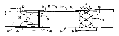
FIGS. 1A and 1B illustrate a preferred embodiment of an
integrated display 10 according to the present invention. Display 10 includes
a
substrate 12 having a first surface 14 and a second surface 16. 'Substrate 12
,can
be embodied as virtually any type of substrate, carrier, panel, &tc. Although
illustrated as planar and having uniform thickness, substrate 12 can take any
virtually any other form. For example, itcan have regularly or irregularly
varying
non-uniform thickness. It can be curved, rippled, or have any variety
olcomplex
shapes and cross-sections. In a typical embodiment, substrate 12 might be a
printed wiring board, such as an FR4 board with a one-half ounoecopper layer
and an OSP or HASL finish. In other embodiments, substrate 12could be an
exterior panel of a domestic appliance, such as a coffee maker or washing
machine, a dash panel or other interior panel of an automobile, or a panel ol:
any
other machine or piece of equipment. These are but afew-examples of substrates
into which a display can be integrated according to the.present invention.
further,
6
CA 02514463 2005-07-26
WO 2004/068448 PCT/US2004/002510
although first surface 14 and second surface 16 are illustrated as generally
opposed, parallel surfaces, first and second surfaces 14 and 16 could be
related in
any number of other ways. For example, first and second surfaces 14 and 16
could be at right angles to each other.
Substrate 12, as illustrated in FIG. 1B, includes two rectangular
penetrations 18. In other embodiments, substrate 12 may include more or fewer
than two such penetrations, and such penetrations may be of any regular or
irregular shape, including, without limitation, circular, square, elliptical
or free
form. Penetrations 18 may be formed by drilling, molding, punching, or other
suitable techniques. Each penetration 18 includes an entrance opening 20, an
exit
opening 22 and a side wall 24.
Penetrations 18 function as light guides or housings for light
guides. Light is coupled from a light source into entrance opening 20. The
light
reflects off of the internal walls of the light guides so that the light
ultimately
leaves the light guide at the exit opening.
In a preferred embodiment, as illustrated in FIG. lA, penetrations
18 function as light guides. In order to best enable penetration 18 to
function as a
light guide, side wall 24 preferably is impervious to light transmission to
prevent
light dissipation or diffusion through substrate 12. To this end, side wall 24
preferably is plated with a reflective coating 26, as shown in FIG. 1A. In
alternate
embodiments, side wall 24 can be coated with, for example, white paint or
other
non-transparent materials. Conceivably, side wall 24 could be left uncoated.
In
such an embodiment, substrate 12 preferably would be made of a material which
7
CA 02514463 2005-07-26
WO 2004/068448 PCT/US2004/002510
inherently reflects light or does not substantially transmit light because
such
materials would tend to reduce light dissipation through the substrate.
In an alternate embodiment, as illustrated in FIG. 2, penetrations 18 function
as
housings for light guides. In this embodiment, penetrations 18 are filled with
an
epoxy material 28 having a high refractive index, with the epoxy material
comprising the light guide. Such material allows light transmission though
penetrations 18, from the first side to the second side of substrate 12, but
prevents
or retards light dispersion into substrate 12. Other materials having
desirable
optical, mechanical and electrical properties can be used in lieu of epoxy 28.
In
another embodiment, not shown in the drawings, a discrete light guide, such as
a
light pipe could be installed in penetration 18. In the foregoing embodiments,
side wall 24 can be, but need not be coated as described above in connection
with
the FIG. 1A embodiment. A separate light pipe assembly with apertures built
into
it could serve as the light guide in a similar fashion.
A display according to the present invention can include a diffuser
30 located at or near exit opening 22. The purpose of diffuser 30 is to
diffuse
light exiting penetration 18 which might otherwise be channelized, thus
enhancing readability of the display by the user. To this end, diffuser 30 can
be
made of any variety of light transmissive materials. In preferred embodiments,
diffuser 30 can cover a substantial portion of second surface 16, as shown in
FIGS. 1A and 2, or it can simply cover a smaller portion of second surface 16
proximate exit opening 22. Diffuser 30 can include printing or other
decoration
(not shown) to enhance the functionality of the display (and of any other
8
CA 02514463 2005-07-26
WO 2004/068448 PCT/US2004/002510
components associated with the substrate), or for purely decorative purposes.
Diffuser 30 can be embodied as, for example, a fascia, an overlay, a piece of
glass, or any other structure that aids in diffusing light exiting penetration
18.
Display 10 further includes a light source 34 adapted to introduce light to
entrance
opening 20, as shown in FIGS. 1A, 1B and 2. Preferably, light source 34 takes
the form of a low profile LED mounted to first surface 14 of substrate 12,
proximate entrance opening 20. In other embodiments, light source 34 could be
a
lamp, an EL, OLED, PLED, vacuum fluorescent or light source. Although light
source LED is illustrated in a particular orientation with respect to
penetration 18,
other orientations are possible, as well.
In another embodiment illustrated in FIG. 3, substrate 12 defines
one or more cavities 18A in lieu of (or in addition to) penetrations 18.
Cavities
18A are similar to and provide essentially the same function as penetrations
18,
except that cavities 18A do not completely penetrate substrate 12. Instead, a
thin
layer of substrate material 12A remains where exit opening 22 is located in
the
FIGS. 1A and 2 embodiments. Thus, each cavity 18A includes an entrance
opening 20, a side wall 24 and a closed end 32. Side wall 24 of cavity 18A can
be
coated with a reflective or other non-transparent material (not shown), as
discussed above, so that cavity 18A can function as a light guide.
Alternatively,
cavity 18A can be filled with a refractive material (not shown), as discussed
above, which can function as a light guide. In such embodiments, at least thin
layer of substrate material 12A is transparent or translucent so that light
may be
transmitted therethrough and be visible to the user. Thus, thin layer of
substrate
9
CA 02514463 2005-07-26
WO 2004/068448 PCT/US2004/002510
material 12A can function as a diffuser, obviating any need for a separate
diffuser,
such as diffuser 30 as illustrated in FIGS. 1A and 2 and described above.
Notwithstanding, a separate diffuser 30 may be layered or screen-printed on
surface 16.
In another alternate embodiment, illustrated in FIG. 4, the light
source is disposed on a carrier, for example, a printed wiring board, separate
from
the substrate comprising the light guide. Here, light sources 34, for example,
surface mount LEDs, are disposed on carrier 112A, which can include other
components, such as sensors, as discussed above. Substrate 112B includes
cavities 18A, as discussed above. In other embodiments, substrate 112B could
include penetrations in addition to or in lieu of cavities 18A. Carrier 112A
is
attached to substrate 112B using adhesives or other suitable attachment means
such that light sources 34 mounted on carrier 34 are substantially aligned
with
cavities 18A (and/or penetrations) in substrate 112B. An optional diffuser 130
can be attached to the viewed surface (here, the opposing surface) of
substrate
112B, as described above.
In practice, a seven-segment display could be constructed by
tooling (such as by punching or NC drilling) or molding a substrate (such as a
printed wiring board) with penetrations corresponding to the seven segments,
plating the side walls of the penetrations using known plating techniques, and
attaching a suitable light source (such as a surface-mount LED of appropriate
color) proximate the entrance opening of each penetration using a suitable
technique (such as a reflow-solder technique, using known surface-mount
CA 02514463 2005-08-11
component process .equipment), opposite the exit opening and any diffuser-or
fascia that might be located proximate theexit opening. Other user interface
components (such as sensors or other components) could be mounted to the
substrate at the same time or as a step during the same production process,
thus.
reducing overall manufacturing cost and yielding an interface of
smallersiaethan
could be manufactured using conventional discrete components. For example,
a sensor 40 can be mounted on the first surface 14 of substrate 12, as shown
in FIG.
1 B. A sensor could be mounted on other portions of display 10 as well. The
illustrated
sensor 40 includes a first electrode 42, a second electrode 44, and an active
component
or integrated circuit 46. Other types of sensors or components could be used
instead of
or in addition to the illustrated sensor. In another embodiment, the
penetrations could
be filled with a material, such as an epoxy, having an appropriate refractive
index, in
lieu of plating. In further embodiments, the substrate could be tooled or
molded with
cavities instead of penetrations, and the penetrations could be filled with a
refractive
material or the side walls thereof could be plated.
The present invention is limited only by the followingtlaims and
not the foregoing embodiments. One skilled in the all would know to make
certain modifications to the foregoing embodiments without tdepartingom the
scope of the claims.
tl