Note: Descriptions are shown in the official language in which they were submitted.
CA 02515073 2005-08-03
WO 2004/070999 PCT/US2004/003008
SITE EQUIPMENT SURVEY TOOL
Cross-Reference to Related Applications)
[001] This application claims priority from U. S. provisional application
number 60/444,437, filed February 3, 2003, which is hereby incorporated by
reference in its entirety.
Field of the Invention
[002] The present invention relates to systems and methods of collecting
information related to physical objects, equipment, and infrastructure at one
or
more sites. More specifically, it relates to a system for tagging and
collecting
virtually unlimited information about a site and about equipment assets
located at
the site.
Pacliground of the Invention
[003] The overall cost of equipment assets located at a site is typically a
significant and ever increasing operating expense faced by large sites or
facilities,
such as govermnent, commercial retailers, and industrial facilities
(collectively
"sites"). Management of sites and tracking the overall cost of equipment
assets at
the site is a difficult and time-consuming task and is even more difficult for
an
enterprise including multiple facilities or sites distributed throughout a
large
geographic region. For example, a large retail chain having sites distributed
at
locations throughout the United States may have hundreds of locations each
requiring independent monitoring and evaluation. Located within these hundreds
of locations may be tens of thousands of pieces of equipment assets, which
contribute to the overall operating cost of its site and of the retail chain
enterprise.
Each year, enterprises lose profits due to their inability to effectively
track
equipment assets.
[~0~.] The overall cost of each individual asset is difficult to track,
because of the enormous volume of equipment assets located throughout a
distributed enterprise. I~/loreoverp the overall cost is a combination of a
number of
factors, such as for example, initial purchase costs, maintenance and repair
costs,
and energy consumption costs. Enterprises currently lack the ability to
effectively
manage and track these assets and to associate various ancillary costs with
the
CA 02515073 2005-08-03
WO 2004/070999 PCT/US2004/003008
asset to enable computation of an overall cost of the equipment asset.
Enterprises
further lack the ability to take an inventory or survey of its equipment
assets
located at various distributed sites and to collect and organize information
relating
to those assets.
[005] Accordingly, there is a need in the art for a system or method for
surveying equipment assets located at one or more sites. There is a further
need
for a system and method for quickly and effectively collecting information
relating to equipment assets of an enterprise.
Brief Summary of the Invention
[006) The present invention, in another embodiment, is a method for
surveying equipment assets located at a site or at multiple distributed sites.
The
method includes gathering and compiling any legacy data relating to equipment
at
a site. Eased on this legacy data and the goals and objectives of the
enterprise, an
equipment asset data structure is created and the legacy data is converted
into this
structure. This data structure, including the legacy data, is then
communicated to
a mobile survey device. An operator then uses the mobile survey device to
survey
the equipment assets located at a site. In one embodiment, quality control is
performed on the survey data to ensure accuracy.
[007] While multiple embodiments are disclosed, still other
embodiments of the present invention will become apparent to those skilled in
the
art from the following detailed description. As will be apparent, the
invention is
capable of modifications in various obvious aspects, all without departing
from
the spirit and scope of the present invention. Accordingly, the drawings and
detailed description are to be regarded as illustrative in nature and not
restrictive.
Brief I~e~eription of the ~ravving~
[~~~) F'ICa. 1 is a flow chart showing a method for surveying equipment
at a site, according to one embodiment of the present invention.
[~~~] FI(a. 1A is a diagram depicting exemplary information collected
for various types of equipment, according to one embodiment of the present
invention.
CA 02515073 2005-08-03
WO 2004/070999 PCT/US2004/003008
[010] FIG. 1B is a diagram depicting exemplary information collected
for various types of equipment, according to a further embodiment of the
present
invention.
[011 ] FIG. 2 is a flowchart showing an equipment surveying method
using a mobile survey device, according to one embodiment of the present
invention.
[012] FIGS. 2A-9 are exemplary screen shots showing portions of a
mobile survey device, according to one embodiment of the present invention.
[013] FIG. 10 is a schematic diagram illustrating an equipment asset
survey system, according to an additional embodiment of the present invention.
[014] FIG. 11 is a schematic diagram showing an equipment asset survey
system, according to a further embodiment of the present invention.
[01 ~] FIG. 12 is a flowchart depicting a method of creating a data
structure, according to one embodiment of the present invention.
[016] FIG. 13 is a flowchart illustrating a method of defining survey
objectives, according to one embodiment of the present invention.
[01'7] FIG. 14 is a flowchart showing a method of creating normalized
lists of expected information, according to one embodiment of the present
invention.
[018] FIG. 15 is a flowchart depicting a method of allowing for data
structure adjustment during the survey process, according to one embodiment of
the present invention.
[019] FIG. 16 is a flowchart illustrating a method of conducting a survey
relating to data associated with refrigeration or HVAC assets for the purposes
of
refrigerant tracking, according to one embodiment of the present invention.
[~20] ~ FIG. 17 is an exemplary representation of a form that can be used
for manual collection of data related to refrigeration or HVAC assets,
according
to one embodiment of the present invention.
[021 ] FIG. 1 ~ is a flowchart showing a method of conducting a survey
relating to data associated with refrigerant stored in cylinders at a site for
the
-3-
CA 02515073 2005-08-03
WO 2004/070999 PCT/US2004/003008
purposes of refrigerant tracking, according to one embodiment of the present
invention.
[022] FIG. 19 is an exemplary representation of a form that can be used
for manual collection of data related to stored refrigerant, according to one
embodiment of the present invention.
[023] FIG. 20 is a flowchart illustrating a method of conducting a survey
relating to refrigerant leakage and repair data associated with refrigeration
or
HVAC assets, according to one embodiment of the present invention.
[024] FIG. 21 is an exemplary representation of a form that can be used
for manual collection of data related to leakage and repair of refrigeration
or
HVAC assets.
[025] FIG. 22 is a flowchart depicting a method of communicating
information from a mobile survey device to a server, according to one
embodiment of the present invention.
[026] FIG. 23 is a flowchart showing a method of identifying an asset
within a database or adding the asset to the database, according to one
embodiment of the present invention.
[027] FIGS. 24-26 are exemplary screen shots showing portions of the
system for identifying an asset or adding an asset to a database, according to
one
embodiment of the present invention.
Detailed Description
[028] The system and method of the present invention is an equipment or
asset survey method that can be used to quickly and efficiently survey
equipment
or assets or any other relevant site characteristics located at one or more
sites.
Any enterprise with numerous assets or equipment to manage has difficulties in
collecting information related to those assets or equipment quickly and
econ~n~ically. The present invention allows such an enterprise to quickly and
easily collect information about numerous assets or equipment at one or more
sites. The system and method of the present invention allows for simple
collection of information for purely information purposes or further for
organizing
-4-
CA 02515073 2005-08-03
WO 2004/070999 PCT/US2004/003008
the collected information and uploading it into additional unique systems for
further processing as part of an asset management system or other similar
systems.
[029] While the system and method of the present invention will be
further discussed herein in the context of equipment or asset information
collection, the information that can be collected by the present invention is
not
limited to equipment or asset information. The system and method of the
present
invention can be used to collect any information of any kind at a site. For
example, information to be collected can include systems comprising several
pieces of equipment such as refrigeration or electrical circuits or wireless
networks. Additionally, information to be collected may include information
related to inventories or stocks of W aterials, signage, furniture, fixtures,
or any
other physical objects at the site or physical infrastructure related to the
site.
[~30] FIG. 1 is a flow chart showing an equipment surveying method 10,
according to one embodiment of the present invention. As shown in FIG. 1, the
equipment surveying method 10 includes gathering and compiling legacy data for
a client's equipment assets (block 12), creating an appropriate data structure
for
collecting and storing equipment information (block 14), importing normalized
legacy data into the data structure (block ~ l6), importing the data structure
and the
legacy data (block 18), and surveying site equipment assets to collect
relevant
information (block 20). In one embodiment, a quality control review is
conducted
on the collected survey data (block 22).
[031 ] Typically, an enterprise will have some pre-existing legacy data
relating to equipment located at its site or various distributed sites. If
present, this
legacy data is reviewed to establish an appropriate data structure (block 14)
for
the following survey process. For example, in one embodiment, the data is
reviewed to identify exemplary equipment categories and subcategories for
inclusion in the data structure. 'The present invention is flexible and
configurable
and allows creation of a variety of data structures, as needed. Also, the
information or fields gathered for each equipment asset are fully configurable
and
-5-
CA 02515073 2005-08-03
WO 2004/070999 PCT/US2004/003008
customizable. The desired fields depend on the goals and objectives of the
enterprise. Generally, the more tasks that the enterprise would like to
perform,
the more fields that are included in the data structure.
[032] For example, if one of the goals of the enterprise is to perform
energy management, certain information relevant to energy management is
included in the fields specified by the data structure. FIG. lA is a diagram
showing the information collected for various types of equipment, according to
one embodiment of the present invention. As shown in FIG. lA, equipment may
be placed into three categories, namely building 11, HVAC 13, and
refrigeration
15. The embodiment of FIG. 1A further categorizes building 11 into lighting
17,
building controls 19, and general usage 21. As shown, HVAC 13 is further
categorized into compressors 23 and~heat stages 25, and refrigeration 15 is
further
categorized into condensers 27, racks 29, compressors 31, and circuits 33.
FIG.
lA further shows several example fields of information that may be collected
for
each type of equipment.
[033] FIG. 1B is a diagram showing the information collected from a
site, according to another embodiment of the present invention. As shown in
FIG.
1B, information may be placed into three categories, namely site data 35, site
photos 37, and equipment data 39. The embodiment of FIG. 1B further shows
several example fields of information that may be collected for each category.
[034] Further exemplary fields are disclosed in co-pending U.S. patent
application number 10/-,-, entitled "Enterprise Energy Management
System," filed on January 30, 2004, which is incorporated herein by reference
in
its entirety and claims priority to U.S. provisional patent application number
60/444,091, filed on January 31, 2003.
[~3~] According to an alternative aspect of the present invention, the
information collected may be any known or collectable equipment information or
data of any kind.
[03~] Creation of a data strdicture (block 14) as shown in FIG. 1 further
includes, where appropriate, identifying acceptable entries or attributes for
a
-6-
CA 02515073 2005-08-03
WO 2004/070999 PCT/US2004/003008
particular field relating to a piece of equipment. In one embodiment, the
acceptable attributes are determined by reviewing the legacy data and
identifying
likely attributes for a site or a set of sites. In another embodiment, the
acceptable
attributes are set using the knowledge of one skilled in the art. The use of a
set of
acceptable attributes assures uniformity and consistency of the data, such
that the
same asset located throughout a set of distributed sites is consistently given
the
same name and set of descriptions: This approach allows robust and accurate
tracking and management of equipment assets.
[037] ~nce a data structure, including fields of interest and acceptable
attributes, is specified, the legacy data (assuming legacy data exists for the
enterprise) is imported into this data structure. According to one embodiment,
this legacy data can serve as the starting point for the survey process.
[033] FIG. 2 is a flow chart showing an equipment surveying method
using a mobile survey device 20, according to one embodiment of the present
invention. As shown in FIG. 2, the equipment surveying method 20 can include
setting goals and objectives (block 30), taking photos at the site (block 32),
collecting information (block 34), specifying the location of assets at the
site
(block 36), reviewing the information collected (block 38), and uploading the
information (block 40). Alternatively, the method 20 can include any variation
of
the above steps, including performing only one or two of the steps. According
to
one embodiment, the step of specifying the location of assets at the site
(block 36)
includes specifying the asset location by placing a representative electronic
object
on an electronic floorplan of the site.
[039] FIGS. 2A-9 are exemplary screen shots showing portions of a
mobile survey device (block 20), according to one embodiment of the present
invention. According to one embodiment, the mobile survey device of the
present
invention has software allowing for the collection of various types of
information.
The software can be any soft~yare that allows for collection of data,
photographic
files, audio files; video files, floorplan files, and any other information
formats
that may be useful for collection of information at one or more sites. In one
_7_
CA 02515073 2005-08-03
WO 2004/070999 PCT/US2004/003008
exemplary embodiment, the mobile survey device has database software allowing
for collection of data, photo or other file software allowing for collection
of
electronic photos, electronic audio files, etc., and design software providing
for
the capability of setting forth floorplans and allowing for editing of such
floorplans. In a further embodiment, the data, photo, and design software are
linked to provide associations between various pieces of information across
the
software applications.
(040] FIG. 2A depicts a portion of the mobile survey device that
represents an overview screen or "process guide" 40, according to one
I0 embodiment of the present invention. The overview screen can include a
location
for indicating when various steps of the survey process have been completed at
the mobile survey device. According to one embodiment, there is a location for
indicating that the user has checked in with the manager 50, taken photos 52,
placed assets 54, viewed a site report 56, and uploaded data 58. From the
process
guide 40, a user can access portions of the device relating to site
information 42,
photos 44, floor plans 46, and an uploading or "review and submit" portion 48.
(04'1 ] FIG. 3 depicts an exemplary screen shot relating to the site
information portion 42, according to one embodiment of the present invention.
The site information portion 42 can include site information relating to site
addresses f0, site contacts 62, site attributes 64, and comments relating to
the site
66. From the site information portion 42, a user can access portions of the
device
relating to the process guide 40, photos 44, floor plans 46, and the review
and
submit portion 48.
(04~] FIG. 4 depicts an exemplary screen shot relating to the site photo
collection portion of the device 44~, according to one embodiment of the
present
invention. The site photo collection portion 44~ in FIG. 4 represents an
e~cemplaxy
photo collection user interface for facilitating collection of site photos.
According
to one embodiment, the site photo collection portion includes locations for a
directory of captured photos 70, an indicator of the current file being
displayed
72, an indicator of the publish name of the file 74, an indicator of the
department
_g_
CA 02515073 2005-08-03
WO 2004/070999 PCT/US2004/003008
to which the photo relates 76, a comments section 78, and the displayed photo
80.
FIG. 4, as shown, depicts the photo collection portion of the device 44 with a
captured photo being displayed. From the photo collection portion 44, a user
can
access portions of the device relating to the process guide 40, site
information 42,
floor plans 46, and the review and submit portion 48.
[043] FIG. 4A depicts an exemplary screen shot relating to the site photo
collection portion of the device 44, according to an alternative embodiment of
the
present invention. FIG. 4A, as shown, depicts the photo collection portion of
the
device 44 with no captured photos available. From the photo collection portion
44, a user can access portions of the device relating to the process guide 40,
site
information 42, floor plans 46, and the review and submit portion 48.
[~44] FIGS. 5 and 6 depict exemplary screen shots relating to a floor
plan editing portion of the device 82, according to one embodiment of the
present
invention. The floor plan editing portion 82 can be used in one embodiment to
specify the location of a particular piece of equipment. According to one
embodiment, the floor plan editing portion 82 includes locations for creating
or
displaying a floor plan 84, for indicating the current floor plan file being
displayed 86, and for selecting various figures, drawing tools, or photos to
create
the floor plan 88. In accordance with one aspect of the present invention, a
user
~ can identify on the floor plan display 84 a representative location where a
particular photograph collected with the device at the site was taken and
'from
what angle.
[045] FIGS. 7 and 8 depict exemplary screen shots relating to a
equipment information collection portion of the device 92, according to one
embodiment of the present invention. The information collection portion 92 can
be used according one embodiment to collect information about a specific piece
of equipment. According to one embodiment, the information collection portion
92 includes locations for item description filters 94, item descriptions 96,
manufacturer descriptions 98, and unplaced asset identification 99. According
to
one embodiment, the unplaced asset identification list indicates each asset
that has
-9-
CA 02515073 2005-08-03
WO 2004/070999 PCT/US2004/003008
been identified but has not yet been placed at its proper representational
location
on the electronic floor plan. Once an asset is placed, it is removed from the
unplaced assets identification list 99. As shown in FIGS. 7 and 8, several
fields
require input using a drop-down box. These drop-down boxes include the
acceptable attributes from which a user selects an appropriate choice.
Typically,
each drop-down box will include an "other" response, where none of the pre-
specified choices are appropriate. This "other" category allows for entry of
any
information that does not fit within one of the specified choices. Further,
this
"other" category can allow for variation and adjustment of the data structure
as is
disclosed further herein.
[046] FIG. 9 depicts an exemplary screen shot relating to the floor plan
portion of the device 46, according to one embodiment of the present
invention.
The floor plan portion 46, according to one embodiment, can be used to
identify
and review various floor plans at a site. According to one embodiment, the
floor
plan portion includes a list of floor plan files 101, a list of floor plan
types 103,
and a floor plan display area 105. From the floor plan portion 46, a user can
access portions of the device relating to the process guide 40, site
information 42,
photos 44, and the review and submit portion 48.
[047] FIG. 9A depicts an exemplary screen shot relating to the review
and submit portion of the device 48, according to one embodiment of the
present
invention. The review and submit portion 48, according to one embodiment, can
be used to review all of the data and files and any other information
collected at a
site and then submit the information for transfer to the server. According to
one
embodiment, the review and submit portion includes a date of main survey
completion 109, and a set of buttons for moving through the review and submit
portion, including buttons to move to the address portion 111, the contacts
area
113, the facts area 1159 the departments area 1179 the photos area 1199 the
assets
area 121, the asset types area 123, and a button to return to the top of the
review
and submit portion 125. From the review and submit portion 4~8, a user can
-10-
CA 02515073 2005-08-03
WO 2004/070999 PCT/US2004/003008
access portions of the device relating to the process guide 40, site
information 42,
photos 44, and the floor plan portion 46.
[048] In one embodiment, the method of the present invention is
implemented in conjunction with an enterprise asset management system for
managing the assets of a distributed enterprise. One example of such a system
is
disclosed in co-pending U.S. patent application number 09/883,779, entitled
"Method and System for Managing Enterprise Assets," filed on June 18, 2001,
which is incorporated herein by reference in its entirety. FIG. 10 is a
schematic
diagram showing a network-based site equipment survey system 100 according to
a second embodiment of the present invention. As shown in FIG. 10, the system
100 includes a server 102 in communication with client computers 104 and
mobile survey devices 106 through a network 108. The client computers 104 and
mobile survey devices 106 may be located at each of the various distributed
sites
requiring an equipment survey. The system 100 allows a distributed enterprise
to
conduct surveys at multiple sites.
[049] As further shown in FIG. 10, in one embodiment, the server 102 is
in communication with a service database 110 and an asset or equipment
database
112. The client computers 104 are in communication with individual pieces of
equipment through an asset/equipment interface 114. In one embodiment, the
interface 114 includes software to translate and normalize signals received
from
various types of equipment, such as that disclosed in co-pending U.S.
application
number 101734,725, filed December 12, 2003, which is incorporated herein by
reference in its entirety. In one embodiment of the present invention, the
system
100 further tracks and manages refrigerant loss in the enterprises various
refrigeration circuits, as disclosed in co-pending U.S. application number
10/429,619, filed May 5, 2003, which is incorporated herein by reference in
its
entirety.
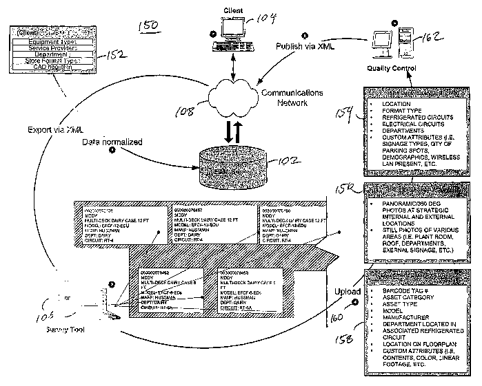
(~~~] FIG. 11 is a diagram showing a survey process 150 for using the
system 100 to conduct a survey of equipment assets located at a site. As shown
in
FIG. 11, the survey process 150 includes starting with legacy data that
relates to a
-11-
CA 02515073 2005-08-03
WO 2004/070999 PCT/US2004/003008
site and was collected from a site 152 prior to the start of the survey
process, such
as for example, equipment types, service providers, departments or zones,
store
format types, and CAD floorplans. This legacy data is normalized and imported
into the server 102 prior to beginning the survey process. In one embodiment,
the
legacy data is imported prior to beginning the survey process and then
normalized
by the server 102. The server 102 then either executes software to create a
data
structure as specified above, or a user evaluates the data and creates an
appropriate structure.
[051 ] FIG. 12 depicts a method of creating a data structure 200,
according to one embodiment of the present invention. The method includes
defining survey objectives (block 202), creating normalized lists of expected
information (block 204), and allowing for data structure adjustment during the
survey process (block 206).
[05~] FIG. 13 is a flowchart depicting a method of defining survey
objectives (202), according to one aspect of the invention. The process of
defining survey objectives can vary significantly depending on the type of
survey
and the characteristics of the site. According to one embodiment, the process
includes determining the purpose of the survey (block 212), determining the
format of the site (block 214), and determining the logistics of executing the
survey (block 216). Alternatively, there can be other or different steps
involved
in defining survey objectives.
[053] The process of determining the purpose of the survey (block 212)
can vary depending on the desires of the client, the type of site, and any
number
of other factors. One survey example is an information equipment survey for
the
simple purpose of determining what pieces of equipment or assets are present
at a
site or sites. Another example would be an equipment survey in preparation for
refurbishment of a site. In this example, it may be helpful to first determine
what
equipment is present at the site in order to determine, for example, what
needs to
be refurbished and at what cost. The purposes of the survey can include
preparation for significant equipment relocation or for a brand conversion. A
-12-
CA 02515073 2005-08-03
WO 2004/070999 PCT/US2004/003008
brand conversion can include the alteration of signage, fixturing, and other
physical objects at the site to address a change in corporate or brand
identity.
Further, the survey may be an equipment survey at a site scheduled for
closing.
Alternatively, the survey may be for any additional purpose for collecting
equipment or asset information. In a further alternative, the survey may be
for
any purpose related to collecting information related to any physical objects
or
physical infrastructure at a site or sites, such as a survey of stocks or
inventories
of materials such as refrigerants, solvents, or any other inventory or stock
materials that may be of interest at a site or sites.
[054] The process of determining the format of the site (block 214) can
include determining the physical structure or layout of the site. For example,
the
site may be a convenience store, a warehouse, or any other type of site. Part
of
this process can include, according to one embodiment, obtaining any floorplan
information related to the site that is available fxom the client. In a
further
embodiment of the present invention, the system of the present invention
includes
obtaining a floorplan in an electronic format or converting the floorplan to
an
electronic format. The format of the site can be important not only for
information purposes, but also because information related to the format of
the
site can influence expectations related to equipment, location of equipment,
amount of equipment, other physical objects of interest, and any expected
linkages between equipment and any department or work center associated with
the equipment.
[055] The process of determining logistics related to a survey (block
216) is a process of planning for implementation relating to personnel and
other
survey requirements. According to one embodiment, logistics determination can
include the number of people required to perform a survey, the amount of time
and expense of transporting the people to the site, the amount of time and
expense
of performing the survey, and various other pieces of information relating to
the
execution of the survey. The logistics can vary significantly depending on the
enterprise and the site.
-13-
CA 02515073 2005-08-03
WO 2004/070999 PCT/US2004/003008
[056] FIG. 14 is a flowchart depicting a method of creating normalized
lists of expected information (204), according to one aspect of the invention.
The
process of creating normalized lists can also vary significantly depending on
the
type of survey, the characteristics of the site, and various other factors.
According
to one embodiment, the process includes determining expectations related to
equipment (block 220), site format (block 222), photographs (block 224), and
tasks for survey personnel (block 226). Alternatively, there can be other or
different steps involved in creating normalized lists of expected information.
[057] The process of determining expectations related to equipment
(block 220) can include determining and creating a field for any information
to be
collected related to equipment. Part of this process can include, according to
one
embodiment, determining the type of equipment expected to be present at the
site,
including the make, model, categorization as to overall use, and any related
characteristics of the equipment, determining the name assigned to the piece
of
equipment, the location of the equipment at the site, determining the
attributes for
which to collect information for each piece of equipment, and any other
information relevant to the equipment. ~ther exemplary information that may be
relevant to this process includes information relating to refrigeration and
HVAC
equipment such as EPA classification. Determining information relating to
equipment type can be important, because it is possible that the system of the
present invention already contains some information relating to certain types
of
equipment that can be accessed upon identification of the equipment type.
[058] The process of determining expectations related to the site format
(block 222) can include determining and creating a field for any information
to be
collected related to site and any characteristics of interest related to the
site. Part
of this process can include, according to one embodiment, determining
expectations with respect to the type of site, the si~.e of the site, the
existence of
and number of any departments at the site, the titles or positions of
personnel at
the site, and any other information of interest relating to site format and
site
characteristics.
-14-
CA 02515073 2005-08-03
WO 2004/070999 PCT/US2004/003008
[059] The process of determining expectations related to photographs
(block 224) can include determining expectations as to photographs that may be
needed or may be of interest relating to the site. Further, the process of
determining expectations related to tasks for survey personnel (block 226) can
include determining expectations related to any special steps or procedures
that
should be taken by the survey-taker during the execution of the survey.
[060] FIG. 15 is a flowchart depicting the process of allowing for data
structure adjustment during the survey process (206), according to one aspect
of
the present invention. The process of allowing for data structure adjustment
is a
process by which the system and method of the present invention provides for
flexibility and variability in its data structure. That is, the present
invention
according to one embodiment allows for adjustment of the data structure during
execution of a survey to account for information that was not allowed for in
the
original data structure. The mobile survey device, according to one
embodiment,
allows for entry of information that was not provided for in the data
structure
(block 232). Upon importation of the survey information into the online
system,
the system automatically identifies any information that does not fit within
the
pre-established data structure (block 234) and the structure can be adjusted
to
account for such information going forward in future surveys or further
execution
of the same survey (block 236).
[06'1 ] Once a data structure is created and includes the legacy data, a file
is exported to the mobile survey device. The file can be communicated using
any
known communication technique. In one embodiment, for example, the file is
encrypted and posted to an FTP site where a user of the mobile device 106 can
access and download the file. The mobile survey device 106 can be any type of
device known in the art, such as a notebook computer, a handheld computer, or
a
personal digital assistant. The mobile surrey device 106 can have continuous
connectivity to the network (e.g., Internet) using a vrixeless oa° a
wia°ed technique
or can use periodic connectivity as needed.
-15-
CA 02515073 2005-08-03
WO 2004/070999 PCT/US2004/003008
[062] A user operates the mobile survey device as described to collect
information relating to various equipment assets located at the site. In one
embodiment, the user first collects general site information, such as that
shown in
blocks 154 and 156 in FIG. 11. According to one aspect of the invention, for
example, a user navigates the site in the following 'systematic fashion. Upon
locating an asset, the user locates the asset on the floor plan using a double-
click.
This double-click on the floor plan opens a data entry window. The user then
places and inputs a barcode number and selects equipment type and any
requested
categories or sub-categories. The user then enters all other requested
information,
using a drop-down menu system including pre-specified attributes as specified
above. Various examples of information that axe collected in one embodiment
are
shown in FIG. 11. For example, the equipment information (shown in block 158)
may include asset category, asset type, model, manufacturer, department,
associated refrigeration circuit, location on floor plan, and any other
desired
attributes. ~thers skilled in the art will envision other types of information
that
may be useful as well.
[063] FIG. 16 is a flowchart depicting a method of conducting a survey
relating to data associated with refrigeration or HVAC assets for the purposes
for
refrigerant (tracking 300, according to one embodiment of the present
invention.
The method includes collecting store information (block 302), collecting a
system
identification (block 304), collecting system information (block 306), and
adding
comments (block 310). According to one embodiment, the method includes
collecting rack information (block 308).
[064] According to one embodiment, the collection of store information
can include, but is not limited to, such information as, for example, store
number,
date, contractor group, technician name, store address, the technician's EPA
certification number, and technician phone number. Alternatively, the store
information can include any information about the stoic that is relevant.
[0~~] According to one aspect of the invention, the collection of system
information can include, but is not limited to, such information as, for
example,
-16-
CA 02515073 2005-08-03
WO 2004/070999 PCT/US2004/003008
EPA category, charge determination method, full charge capacity, refrigerant
type, observed system status, system configuration, system type, onsite charge
documentation detail, and system description. According to one embodiment, the
charge determination method, which is the method for calculating the charge,
can
be chosen from four different methods, including (1) onsite charge
documentation, (2) calculation, (3) measurement, or (4) manufacturer's
information (established range). In one aspect of the invention, the system
status
can be chosen from (1) normal operation, (2) operating under extension, (3)
shutdown, or (4) retrofit in progress.
[066] In one embodiment, the collection of rack information can include,
but is not limited to, such information as, for example, rack manufacturer,
receiver volume, compressors, and total horsepower.
[06~'] According to one embodiment, the method of conducting a
refrigerant tracking survey 300 is performed with the survey tool.
Alternatively,
the information is collected manually. FIG. 17 is an exemplary depiction of a
form that can used for manual collection of the data related to the
refrigeration or
HVAC assets. Subsequently, the data collected on the form in FIG. 17 can be
inputted into the survey tool or into the appropriate application at the
server.
[068] FIG. 18 is a flowchart depicting a method of conducting a survey
relating to data associated with refrigerant stored in cylinders at a site for
the
purposes of refrigerant tracking 400, according to one embodiment of the
present
invention. The method includes collecting store information (block 402) and
collecting on-site refrigerant inventory information (block 404).
[06J] According to one embodiment, the collection of store information
can include, but is not limited to, such information as, for example, store
number,
date of survey, contractor group, technician name, store address, EPA
certification
number, and technician phone number. Alternatively, the store information can
include any information about the store that is relevant.
[0~0] According to one aspect of the invention, the collection of on-site
refrigerant inventory information can include, but is not limited to, such
-17-
CA 02515073 2005-08-03
WO 2004/070999 PCT/US2004/003008
information as, for example, refrigerant type, whether the refrigerant has
been
marked as reclaimed, cylinder size, charge remaining in the cylinder, and
cylinder
identification.
[071 ] According to one embodiment, the method of conducting a stored
refrigerant survey 400 is performed with the survey tool. Alternatively, the
information is collected manually. FIG. 19 is an exemplary depiction of a form
that can used for manual collection of the data related to the stored
refrigerant.
Subsequently, the data collected on the form in FIG. 19 can be inputted into
the
survey tool or into the appropriate application at the server.
[072] FIG. 20 is a flowchart depicting a method of conducting a survey
relating to refrigerant leakage and repair data associated with refrigeration
or
HVAC assets 450, according to one embodiment of the present invention. The
method includes collecting store information (block 452), collecting system
information (block 454), collecting service information (block 456), and
collecting technician comments (block 458).
[073] According to one embodiment, the collection of store information
can include, but is not limited to, such information as, for example, store
number,
date of survey, technician name, store address, the technician's EPA
certification
number, and technician phone number. Alternatively, the store information can
include any information about the store that is relevant.
[074] According to one aspect of the invention, the collection of system
information can include, but is not limited to, such information as, for
example,
system identification, refrigerant type, and any other relevant system
information.
[075] According to one aspect of the invention, the collection of service
information can include, but is not limited to, such information as, for
example,
amount of refrigerant added, amount of refrigerant recovered, date of most
recent
service, service reference number, leak status (whether the leak is repaired
or a
repair was attempted).
[075] According to one aspect of the invention, the collection of
technician comments can include, but is not limited to, such information as,
for
-18-
CA 02515073 2005-08-03
WO 2004/070999 PCT/US2004/003008
example, exact leak location, whether all identified leaks were repaired,
method
of leak repair verification, whether a return trip is required, and additional
comments. The leak repair verification methods include bubble,
electronic/ultrasonic, pressure, evacuation, and dye inject.
[077] According to one embodiment, the method of conducting a
refrigerant leakage and repair survey 450 is performed with the survey tool.
Alternatively, the information is collected manually. FIG. 21 is an exemplary
depiction of a form that can used for manual collection of the data related to
the
leakage and repair data. Subsequently, the data collected on the form in FIG.
21
can be inputted into the survey tool or into the appropriate application at
the
server.
[p7~] ~nce the survey process is complete, a file is created and uploaded
160 to a quality control point 162. According to one embodiment, quality
control
allows for determining whether all information collection has been
successfully
completed, or whether further information collection is required. For example,
if
collected information relates to the wrong equipment or is faulty in some
fashion,
the quality control point allows for identifying these collection failures
while
survey collectors are still at the site or within a reasonable distance of the
site and
further allows for instructing the collector to remedy the failure.
[079] According to one aspect of the invention, the quality control
process may involve assigning all "other" or "unknown" choices to an
appropriate
attribute. Where necessary, this process may include adding new allowable
attributes to the pre-specified data structure. Alternatively, no quality
control is
performed.
[0~0] After quality control is completed, the survey data is
communicated via the network 10~ to the server 102 for further processing
using
the techniques described in the various applications v~hich are incorporated
herein. This communication to the server is the process of making the
information available to the various applications. FIG. 22 is a flowchart
depicting
a method of communicating the information to the server 460, according to one
-19-
CA 02515073 2005-08-03
WO 2004/070999 PCT/US2004/003008
embodiment of the present invention. The method includes converting the data
into a format compatible with the applications at the server (block 462),
transferring the data and files to the server (block 464), further converting
the data
at the server (block 466), and adding additional linkages between imported
data
and data already available at the server (block 468).
[081 ] In one aspect of the invention, the mobile survey device has
applications that are different than or formatted differently than the
applications at
the server. Thus, some or all of the information at the device must be re-
formatted prior to uploading or importing to the server. Given that the mobile
device, according to one embodiment, creates linkages between the information
in
the various applications during collection of information, the conversion and
data
transfer process of the present invention occurs such that such linkages are
not
lost. Alternatively, certain of the applications at the device have the same
format
as the correlating applications at the server, and no re-formatting is
required.
According to a further alternative embodiment, the data applications at the
device
and the service have different formats, while the photo and audio file
applications
have the same format.
[082] In an embodiment in which the data applications are different but
the file applications are the same, the data is converted into a format
compatible
with the server applications (block 462). The data applications include any
database application and any design application. In one exemplary embodiment,
the database application at the device is Microsoft Access and the application
at
the server is Oracle. According to one embodiment, the conversion is a two-
step
process. First, the database data in the Access format is first converted to
the
AIL format. This step includes an automatic database mapping step - wherein
the data is identified by field and thus can be transferred to the appropriate
field in
the server application - because the format of an 1L file inherently organises
data such that it is labeled with its intended use.
[08~] In a further exemplary embodiment, the design application at the
device uses .dwg files and the application at the server uses .mwf files. The
-20-
CA 02515073 2005-08-03
WO 2004/070999 PCT/US2004/003008
conversion process takes place by a known conversion process in which the .dwg
file is converted into a .mwf file. Any linkages created at the mobile device
are
retained during the conversion using, according to this embodiment, an
application called Autodesk Map.
[084] After conversion (block 462), the converted data and files are
transferred to the server (block 464). According to this embodiment, the files
are
transferred without conversion because the file applications in the device and
the
server are compatible. Alternatively, the applications may not be compatible
and
then conversion would be necessary.
[085] After transferring the data to the server, a further conversion
process may be required (block 466) according to one embodiment of the present
invention. For example, if the database data has been converted to an XML file
as described above and the server database software is Oracle, the XML file
must
be converted to a format compatible with ~racle. Alternatively, the data is
compatible with the applications at the server upon being moved from the
device
and no conversion is necessary.
[086] In one alternative -aspect of the present invention, once the
information is transferred into the server, that information can be linked to
information that already existed within the server (block 468). This can be
accomplished by any known method for linking information.
[087] In one embodiment, the first step executed by the mobile survey
device 106 in collecting information specified to a particular asset, is to
check
whether the asset is included in the legacy data. This will facilitate data
collection
and maximize the use of any legacy or pre-existing data.
[~88] FICa. 23 is a flowchart depicting a method of identifying an asset
within a database or adding the asset to the database 600, according to one
embodiment of the present invention. The method can include identifying the
asset in the legacy list (block 602), and if the asset is not in the legacy
list, adding
the asset to the database (block 604). The method further includes inputting
or
reviewing all attributes of the asset (block 606).
-21-
CA 02515073 2005-08-03
WO 2004/070999 PCT/US2004/003008
[089] According to one embodiment, the step of identifying the asset in
the legacy list 602 can include performing a filter. That is, the user inputs
any
identification that will reduce the number of possible choices presented by
the
system of the present invention. For example, the filter may be performed by
inputting the model number of an asset into the system, which causes the
system
to present a list of choices, and then the correct asset can be chosen from
that
filtered list, thereby locating the asset within the database. Alternatively,
the
filtering step can occur by inputting any other or additional relevant
information,
such as a model identification, a serial number, a department identification,
a
manufacturer, a supplier, etc., that will allow for identifying the asset. In
a further
alternative, no filter step is required and an appropriate informational input
automatically identifies the asset.
[090] regardless of whether a filter is performed, the asset must be
identified 602. The identification step can include reviewing the legacy data
to
ensure that the correct asset has been identified.
[091 ] FIG. 24 is an exemplary screen shot relating to a portion of the
system providing for locating an asset in a legacy list 612, according to one
embodiment of the present invention. The asset location portion 612 of the
system can be used to locate an asset in a legacy list as described in FIG.
23.
Alternatively, the asset location portion 612 can be used in any way that
provides
for locating an asset. The asset location portion 612, according to one
embodiment, includes a filter portion 614 for performing the filter, a
identification
portion 616 for performing the identification of the asset, and a continue
button
618 if the asset is identified or a button to press if the asset is not found
620.
[09~] returning to FIG. 23, if the asset cannot be found in the legacy
data, then the asset must be added to the database 604. To add the asset 604,
according to one aspect of the invention, the asset is categorised and then
identified. The categorisation step can include a description of the category
of the
asset and a description of the asset. The identification step can include
identification of such characteristics as the model, barcode number, serial
number,
_22_
CA 02515073 2005-08-03
WO 2004/070999 PCT/US2004/003008
department, and manufacturer of the asset. Alternatively, the identification
step
can include identification of any relevant characteristic of the asset.
j093] FIG. 25 is an exemplary screen shot relating to a portion of the
system providing fox adding a new asset to the database 624, according to one
embodiment of the present invention. The asset addition portion 624 of the
system can be used to add an asset to the database as described in FIG. 23.
Alternatively, the asset addition portion 624 can be used in any way that
provides
for adding an asset. The asset addition portion 624, according to one
embodiment, includes a categorization portion 626, an identification portion
628,
and a continue button 630 to proceed to the next portion of the system when
the
addition is complete.
[~94] returning to FIG. 23, once the asset is found or added, then all
attributes of asset must be inputted into the database 606. According to one
embodiment, the attributes are all characteristics of the asset that are
unique to
that specific asset. For example, attribute categories that might be inputted
include color, condition, dimensions, components, or any other type of
attribute
that is unique to that specific asset.
[095] FIG. 26 is an exemplary screen shot relating to a portion of the
system providing for inputting attributes of an asset to the database 634,
according to one embodiment of the present invention. The attribute input
portion
634 of the system can be used to input attributes of an asset to the database
as
described in FIG. 23. Alternatively, the attribute input portion 634 can be
used in
any way that provides for inputting attributes of an asset. The asset
attribute
addition portion 634, according to one embodiment, includes fields for
inputting
information relating to color 636, condition 638, shelf type 640, shelf
dimensions
641, and shelf components 642, along with additional fields for additional
attributes.
[~9~] Although the present invention has been described with reference
to preferred embodiments, persons skilled in the art will recognize that
changes
-23-
CA 02515073 2005-08-03
WO 2004/070999 PCT/US2004/003008
may be made in form and detail without departing from the spirit and scope of
the
invention.
-24-