Note: Descriptions are shown in the official language in which they were submitted.
CA 02515527 2005-08-09
GUIDE SYSTEM FOR AN EXTERNALLY OPERATED PART OF A CLOSING
UNIT
The invention relates to a guide system for an externally operated part of a
closing unit, in particular for tool holders of a closing unit, according to
the
preamble of claim 1.
In the following, reference is made to a closing unit for a plastics
processing
machine with at least one tool holder in which a tool, also called mold or
half
mold, is held. It should be expressly noted, however, that the present
invention is
equally applicable for other externally operated parts of closing units.
Closing units of plastics processing machines, such as polyurethane
installations,
normally have two mold holders which are movable for closing and opening of
the closing unit and thus at the same time of the accommodated mold. In this
context, reference is made to German patent publication DE 101 52 392 which
describes a closing unit for a plastics machine. The illustrated closing unit
includes a lower mold holder and an upper mold holder which are each
swingable about a common axis. During operation of the entire closing unit,
the
lower mold holder is moved back and forth between two positions, namely a
lower position in which the mold elements are placed into a mold or mold parts
can be removed, and an upper position in which the starting material is
introduced and the closing unit overall is closed to allow reaction of the
foam
components.
In DE 101 52 392, the closing units themselves are fixedly disposed at one
location, only the mold holders are swingably mounted.
It is, however, known, to arrange for example several closing units upon a
rotary
platform, with the individual closing units successively undergoing the same
1
CA 02515527 2005-08-09
operating steps during operation of the rotary platform. For example, a
starting
material may be introduced, when the closing unit is open. At the same time,
the
reaction takes place in other closing units. In still another closing unit, a
finished
molded part may be withdrawn at the same time. The use of such devices -
likewise as in DE 101 52 392 - requires operation, especially pivoting, of the
various parts of the closing unit in a predefined manner.
A method for external operation of a mold holder is know per se, using a
guiding
slot mechanism, whereby a cam roller is arranged upon an externally operated
(i.e. from outside the closing unit) part of a closing unit, for example the
lower
mold holder, for running on a support structure. Conventionally, the support
structure is realized by a rail arrangement whose respective height is so
constructed via for example a rotation section of the rotary platform that the
pivoting position of the cam roller mounted to the part being externally
actuated
can be adjusted as the cam roller is supported and rolls off. Concretely, the
support structure includes, for example, two ramp portions, namely an upwardly
directed ramp and a downwardly directed ramp as well as a rail part at
constant
height disposed in-between. When the cam roller of the part to be externally
operated reaches the upwardly directed ramp, this part of the closing unit is,
for
example, elevated to an upper position as the cam roller rolls on this support
section, and remains there for as long as the cam roller rolls on the further
rail
section at constant height. When the cam roller then rolls finally along the
downwardly directed ramp, the part to be externally operated is moved by its
own
weight downwards and ultimately brought to a standstill in a predefined
position
by a stop.
The use of such rigid rails for a support structure suffers, however, the
drawback
of experiencing substantial wear as a result of friction when imprecise
adjustment
causes a relative movement between cam roller and rail. Moreover, the precise
2
CA 02515527 2005-08-09
manufacture of such rail system has proven expensive and complicated.
Complex is also the replacement of certain rail portions.
It is an object of the present invention to minimize in a guide system of the
afore-
stated type the wear at least on some partial sections and to ensure easy
replacement.
This object is attained by the features set forth in claim 1.
An essential feature of the invention is thus the provision of at least one
section
of the support structure with a freely moveable support roller having an axis
in
substantial parallel or tangential relationship to the movement direction of
the
closing unit or cam roller on the closing unit. As a consequence of this
constructive design, there is no sliding friction, even when the point of
contact of
the cam roller on the support structure shifts because the support roller is
turned
in the respective manner during such shift of the point of contact and the cam
roller rolls thereby in its axial direction on the support roller. In the
absence of a
sliding friction, wear on the inventive section of the support structure can
be
significantly reduced. Thus, the mold holder can be operated externally
without
friction-based wear, even in the presence of misalignments and radial
deviations
of the support structure.
Furthermore, the cam roller of the part to be externally operated is acted
upon
not only in one point or line. Rather, the line of contact travels across a
significant
portion of the roller width. Also the support rollers of the support structure
can
travel about the entire circumference according to a statistical distribution.
In
contrast thereto, a rigid pipe would always have only one line of contact with
the
cam roller.
3
CA 02515527 2005-08-09
Overall, minimal wear can be ensured without additional adjustments by an
automatic adjustment of the rolling behavior, compensation of manufacturing
and
assembly tolerances, and simplified exchange of partial sections of the
support
structure.
Of course, the section of the support structure, having at least one freely
moveable support roller, may be provided with several support rollers as well.
In
this case, the support rollers should overlap in their axial extension such as
to
establish a smooth transfer of the cam roller from one support roller to the
next
support roller.
According to a preferred embodiment of the invention, upwardly or downwardly
directed ramps are formed by the sections which include the freely moveable
support rollers. It is these parts of the subassembly that are subject to
stress in
particular, on one hand. On the other hand, precise alignment and construction
of
these sections require particular care when using a rail. When using a support
roller in connection with a ramp, its axis must extend at a certain angle
upwards
or downwards in relation to the movement direction so that lifting or lowering
of
the mold holder becomes possible.
It is not necessarily required to provide the entire support structure by
means of
support rollers. It is also possible, to realize sections in the form of the
conventional guide rail. In particular, the use of a guide rail is appropriate
at such
locations that are easy to adjust and less exposed to stress and which
encounter
anyway little friction-based wear.
Also, there is no need to continuously define the position of the part to be
externally operated through interaction of the cam roller with the support
structure. It is, for example, possible, to spontaneously realize a lower
position of
4
CA 02515527 2005-08-09
the part to be externally operated by providing a further frame element of the
closing element with a stop for this part.
According to a particularly preferred embodiment, at least one closing unit is
arranged on a turntable. Of course, several closing units (e.g. 12 units) may
be
provided on the turntable at same radial distances from the center of the
turntable. The turntable can be operated during operation of the closing unit
so
that the individual closing units move about a circular line. The roller moves
on a
toroidal surface line. When using a turntable, the support structure should be
arranged about a pitch circle and associated to the pivot point. It may
include
preferably an upwardly directed ramp which has been realized by means of the
support rollers, a section with a guide rail, and a downwardly directed ramp
which
has also been realized with support rollers.
Of course, the invention may also be used in oval installations exhibiting a
circular or linear movement of the closing units.
An embodiment of the present invention will now de described in greater detail
by
way of example with reference to the attached drawings, in which:
Fig. 1 shows a greatly schematic side view of a carousel-type installation
with several closing units and a guide system according to the present
invention,
Fig. 2 shows a plan view of a carousel-type system according to Fig. 1,
with the carousel shown only partially,
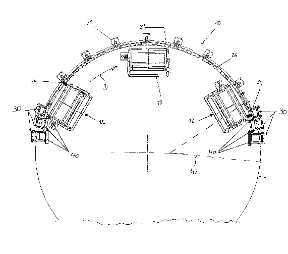
Fig. 3 shows a circular segment of FIG. 2, depicting a detailed view of a
ramp of the guide system according to the invention,
5
CA 02515527 2005-08-09
FIG. 4 shows a portion of the schematic illustration according to Fig. 1 with
the ramp of the guide system according to the invention, and
Fig. 5 shows a portion of a further portion of the carousel of Fig. 1.
The present invention will now be described in greater detail with reference
to a
carousel-type system for PUR installations (polyurethane installations).
However,
the invention is not limited to this system.
Several closing units 12 of a PUR installation (2 in Fig. 1, 3 in Fig. 2), not
shown
in more detail, are securely disposed on a turntable 20 at substantially same
radial distance to its center and in angular offset relationship. Each closing
unit
12 includes a lower mold holder 14 and an upper mold holder 12 which can both
pivot upwardly and downwardly about a common joint axis 18. The closing unit
can be closed or opened in its entirety by pivoting the lower and upper mold
holders 14, 18. As a consequence, the mold holders can be brought into a
position that allows introduction of mold elements in ergonomically beneficial
manner or removal of molded products from the mold.
The present invention is concerned only with pivoting of the lower mold holder
14. The pivot mechanism for the upper mold holder 12 will not be described in
more detail.
In relation to the dimension of the turntable, the lower mold holder 14
includes a
radially outwardly projecting arm having an outer end for arrangement of a cam
roller 24. The rotation axis of the cam roller 24 substantially coincides with
the
radial direction of the turntable; however it may also slightly deviate
therefrom as
a result of the off center arrangement.
6
CA 02515527 2005-08-09
Each cam roller 24 of a closing unit runs upon a support structure which in
the
present case is comprised of two ramps 30 as well as a guide rail 26. Both
ramps
30 as well as the guide rail 26 extend substantially in the form of a circular
segment over a portion of the outer circumference of the turntable 20. The
guide
rail 26 is held by a plurality of stanchions 28 of which only one is
respectively
labeled with a reference character in Figs. 1 and 2. The guide rail 26 extends
-
as shown in Fig. 1 - at constant height.
Provided on each of both ends of the guide rail 26 are two ramps 30, each of
which having three stands 32 as shown in greater detail in Fig. 3 by the
segment
42 cut from Fig. 2. Each stand 32 includes a base 34 which is mounted onto the
ground radially outside the turntable, a support leg 36 arranged on the base,
an
arm 38 disposed on the upper end of the support leg 36, as well as a support
roller 40 disposed on the inner end of the arm 38. The support roller 40 is
held on
both sides in bearings of the arm 38 and freely rotatable about a rotation
axis.
The rotation axis extends here substantially tangential to the rotation
direction D
(see arrow D in Fig. 1 ) of the turntable 20 and slopes upwardly or downwardly
in
relation to the rotation movement.
The mode of operation of the turntable is as follows.
The turntable is rotated in direction of arrow D (Fig. 2) together with the
attached
closing units 12. When the cam roller 24 of a closing unit reaches the ramp
30,
illustrated in Fig. 2 on the left-hand side, it successively runs on the three
support
rollers 40 upwards. To ensure a smooth rolling operation, the ends of the
support
rollers 40 overlap in axial direction so that the cam roller 24, when reaching
one
end of a support roller, bears at the same time on a second support roller.
Once
the cam roller 24 of a lower mold holder 14 has passed the support rollers and
has been elevated - together with the mold holder 14 - to an upper level, it
travels
on the rail 26 to the end thereof. Passage of the ramp 30 causes the lower
mold
7
CA 02515527 2005-08-09
holder to be elevated from a lower position to an upper position. The lower
mold
holder 14 remains in the upper position so long as the cam roller 24 travels
on
the rail 26. When the cam roller 24 travels then in opposite manner to the
first
ramp on the second ramp shown in Fig. 2 on the right-hand side, the lower mold
holder 14 is moved downwards again. In a same manner as in the first ramp, the
cam roller 24 runs successively on three support rollers 40 in overlapping
configuration.
The lower position of the mold holder 14 is defined by the frame of the mold
holder striking against a stop 44. In this position, the cam roller 24 has no
function.
Fig. 4 depicts again the ramp as formed by the three support rollers 40. The
cam
roller 24 is hereby not clearly shown. It travels, however, always on one of
the
support rollers 40.
Fig. 5 illustrates the manner by which the cam roller 24 travels on the rail
26 and
maintains the lower mold holder in the upper position.
The use of the support rollers 40 in the ramp zone prevents a sliding movement
of the cam rollers 24 on a rail and thus excessive wear. Rather, the support
rollers 40 rotate in one or the other direction (substantially in axial
direction of the
cam roller 24), depending on whether the contact point travels inwards or
outwards to the cam roller 24.
In view of the axial change of the contact point upon the cam roller 24, the
latter
is acted upon not only at one spot. Rather, the line of contact travels on the
roller
width, for example upon 70 % of the roller width, thereby also contributing to
a
minimization of wear.
8
CA 02515527 2005-08-09
Thus, there is not necessarily a need to precisely align the individual stands
32
having the support rollers 40 on its upper, inner end in order to minimize
wear as
a consequence of sliding friction. In view of the free rotatability of the
support
rollers, the sliding friction can be easily kept small, even when the support
rollers
are not in precise alignment. Further, the use of several stands with support
rollers is conducive for a simple and cost-efficient replacement. Only the one
support roller has to be replaced which exhibits certain wear after a long
service
life.
Of course, remaining portions of the support structure may also be realized
with
rollers. However, the guide rail can be manufactured in the area of constant
height with more precise tolerances and with a wider running surface so that
the
use of support rollers is not necessarily required here.
In summary, the invention allows prevention of excessive wear, easier
adjustment, compensation of manufacturing and assembly tolerances, as well as
easier replacement of partial sections. In addition, the invention also
permits an
arrangement of the cam roller axes in such a way that the touching tangent is
prevented from extending through the pivot point of the closing unit.
9
CA 02515527 2005-08-09
LIST OF REFERENCE CHARACTERS
Carousel-type system with closing
units
12 closing unit
5 14 lower mold holder
16 upper mold holder
18 joint axis
turntable
22 central support with bearing
10 24 cam roller of the lower mold
holder
26 rail
28 rail support
ramp
32 stand
15 34 base
36 support leg
38 arm
support roller
42 segment
20 44 stop
D rotation direction