Note: Descriptions are shown in the official language in which they were submitted.
CA 02515627 2005-08-10
1
Lift installation with a cage and equipment for detecting a cage position, as
well as a
method of operating such a lift installation
The invention relates to a lift installation with a cage and equipment for
detecting a cage
position, as well as to a method of operating such a lift installation,
according to the
definition of the patent claims.
It is known to determine the cage position of a lift installation in order to
derive from this
information control signals which are further used by the lift control. Thus,
German Utility
Model DE 9210996 U1 teaches equipment for determining the cage position by a
magnet
strip and magnet head for reading the magnet strip. The magnet strip has a
magnetic
coding and extends along the entire travel path of the cage. The magnet head
fastened to
the cage contactlessly leads the coding. A cage position is determined from
the read-off
codings.
A development of this equipment is disclosed in Patent Specification WO
03011733 Al,
which also forms the closest state of the art for the present invention.
According to the
teaching of this patent specification the coding of the magnet strip consists
of a plurality of
code marks arranged in a row. The code marks are magnetised either as south
pole or as
north pole. Several successive code marks form a code word. The code words are
in turn
arranged in a row as a code mark pattern with binary pseudo random coding.
Each code
word thus represents an absolute cage position.
For scanning the magnetic fields of the code marks the equipment of Patent
Specification
WO 03011733 Al comprises a sensor device with several sensors, which enable
simultaneous scanning of several code marks. The sensors convert the different
poling of
the magnetic fields into corresponding binary information. For south poles it
issues a
binary value '0' and for north poles a bit value '1'. This binary information
is evaluated by
an evaluating unit of the equipment and processed into an absolute position
statement
comprehensible to the lift control and used by the lift control as control
signals.
Patent Specification WO 03011733 Al further teaches the use of small sensors
of 3
millimetre length, which are arranged in two mutually adjacent tracks so that
two sensors
come to lie on the length of a code mark. Due to this periodicity of the
sensors which is
CA 02515627 2013-03-26
2
twice as high as that of the code marks the sensors can clearly detect a
transition
between differently poled code marks as a zero transition of the magnetic
field.
In detection of the magnetic field of the code marks the resolution of the
absolute cage
position is equal to the length of one code mark, i.e. 4 millimetres. In
detection of the
transition between differently poled code marks the resolution of the absolute
cage
position is substantially better and amounts to 0.5 millimetres.
A disadvantage of the equipment of Patent Specification WO 03011733 Al is
firstly that
the strength of the magnetic field in normal direction above the code marks
rapidly
decreases and the sensors therefore have to be positioned at a small spacing
of 3
millimetres above the code marks. A further disadvantage of this equipment is
that the
sensors have to be positioned centred above the code marks with a high degree
of
accuracy of +/- 1 millimetre. The sensor device above the code pattern has to
be guided
in complicated manner for a sufficiently large security and adequate
reliability of the lift
installation. This is costly. The cost connected therewith is very large
particularly in the
case of high cage speeds of 10 m/sec.
The present invention has the object of indicating a lift installation with a
cage and
equipment for determining the cage position as well as a method of operating
such a lift
installation, which enables accurate scanning of a code mark pattern by a
sensor device
at low cost without security and reliability being impaired.
This object is fulfilled by the invention according to the definition of the
patent claims. The
lift installation comprises at least one cage and at least one item of
equipment for
determining a cage position. The equipment comprises a code mark pattern and a
sensor
device. The code mark pattern is mounted along the travel path of the cage and
consists
of a plurality of code marks. The sensor device is mounted at the cage and
contactlessly
scans the code marks by sensors. The code marks are arranged in a single track
and the
sensors are arranged in a single track.
In one aspect, the present invention provides a lift installation with at
least one cage and
at least one equipment for detecting a cage position, the equipment comprises
a code
mark pattern and a sensor device, the code mark pattern is mounted along the
travel path
of the cage, the code mark pattern consists of a plurality of code marks, and
the sensor
device is mounted at the cage and contactlessly scans the code marks by
sensors,
CA 02515627 2013-03-26
2a
whereby the code marks are arranged in a single track and the sensors are
arranged in a
single track, characterised in that a mark dimension of the code marks is
between 2.5 and
1 and/or that a track dimension of the track of the sensors is between 2.5 and
2/3.
In a further aspect, the present invention provides a method of operating a
lift installation
with at least one cage and at least one equipment for detecting a cage
position, the
equipment comprises a code mark pattern and a sensor device, the code mark
pattern is
mounted along the travel path of the cage, the code mark pattern consists of a
plurality of
code marks, and the sensor device is mounted at the cage and contactlessly
scans the
code marks by sensors, whereby the code marks are arranged in a single track
and the
sensors are arranged in a single track, characterised in that a mark dimension
of the code
marks are chosen to be between 2.5 and 1 and/or that a track dimension of the
track of
the sensors are chosen to be between 2.5 and 1.
The advantage of the invention consists in that the dimensions of the code
marks and of
the track of the sensors are optimally matched to the signal strength of the
code marks.
Through use of a single track for the code marks and a single track for the
sensors an
efficient and loss-free scanning of the code marks is carried out by the
sensors. The
CA 02515627 2005-08-10
3
arrangement of the sensors in a single track centrally above the track of code
marks
allows a selective scanning of the code marks in the region of high signal
strength. In this
connection there is consideration that a given signal strength of the code
marks on the one
hand decreases towards the edges of the code marks and that on the other hand
it
decreases from a certain spacing above the code marks. The high signal
strengths, which
are scanned efficiently and free of loss in that manner, of the code marks
lead to large
confidence regions in which the sensors can securely and reliably scan the
code marks
with sufficiently powerful sensor signals. It is therefore possible to design
the confidence
region in selective manner and thus arrange the sensors not at a spacing above
the code
marks limited by the signal strength, but at a spacing above the code marks
determined by
the effort in guidance. Through increase in the spacing of the sensors above
the code
marks the outlay for guidance of the sensor device is reduced and yet a high
security and
reliability of the lift installation is guaranteed.
Advantageously, for a given signal strength of the code marks and given
sensitivity of the
sensors the mark dimension of the code marks and/or the track dimension of the
track of
the sensors is or are so selected that the sensors are positionable at maximum
spacing
above the code marks.
Advantageously the mark dimension is less than 2.5 and/or the track dimension
is less
than 2.5.
Advantageously the sensors are guided above the code marks at a minimum
spacing of
15 millimetres, preferably 14 millimetres, preferably 13 millimetres,
preferably 12
millimetres, preferably 11 millimetres, preferably 10 millimetres, preferably
9 millimetres,
preferably 8 millimetres, preferably 7 millimetres, preferably 6 millimetres,
preferably 5
millimetres, preferably 4 millimetres.
The invention is explained in detail in the following with reference to
examples of
embodiment according to Figs. 1 to 10, in which:
Fig. 1 shows,
schematically, a lift installation with a cage and equipment for
determining the cage position,
CA 02515627 2005-08-10
4
Fig. 2 shows, schematically, the construction of a part of equipment for
determining the cage position, with sensor device and code mark pattern
from the state of the art of Patent Specification WO 03011733 Al,
Fig. 3 shows, schematically, the construction of a part of a first form of
embodiment of equipment according to the invention for determining the
cage position, with sensor device and code mark pattern,
Fig. 4 shows, schematically, the construction of a part of a second form
of
embodiment of equipment according to the invention for determining the
cage position, with sensor device and code mark pattern,
Fig. 5 shows a longitudinal view of the sensor device above a code mark of
equipment for determining the cage position from the state of the art
according to Fig. 2,
Fig. 6 shows a longitudinal view of the sensor device above a code mark of
the
first equipment according to the invention for determining the cage position,
according to Fig. 3,
Fig. 7 shows a longitudinal view of the sensor device above a code mark of
the
second equipment according to the invention for determining the cage
position, according to Fig. 4,
Fig. 8 shows a transverse view of the sensor device above a code mark of
equipment for determining the cage position from the state of the art,
according to Figs. 2 and 5,
Fig. 9 shows a transverse view of the sensor device above a code mark of
the first
equipment according to the invention for determining the cage position,
according to Figs. 3 and 6, and
Fig. 10 shows a transverse view of the sensor device above a code mark of
the
second equipment according to the invention for determining the cage
position, according to Figs. 4 and 7.
CA 02515627 2005-08-10
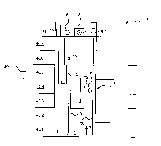
With respect to the lift installation: In the lift installation 10
schematically illustrated in Fig. 1
a cage 1 and a counterweight 2 are suspended at at least one support cable 3
in a shaft 4
in a building 40. The support cable 4 runs over a deflecting roller 5 and is
driven by way of
a drive pulley 6.1 by a drive 6.2. Deflecting roller 5, drive pulley 6.1 and
drive 6.2 can be
arranged in a separate engine room 4', but they can also be disposed directly
in the shaft
4. Through lefthand or righthand rotation of the drive pulley 6 the cage 1 is
moved along a
travel path in or opposite to a travel direction y and serves storeys 40.1 to
40.7 of the
building 40.
With respect to determining the cage position: Equipment 8 for determining the
cage
position comprises a code mark pattern 80 with code marks, a sensor device 81
and an
evaluating unit 82. The code mark pattern 80 has a numerical coding of
absolute positions
of the cage 1 in the shaft 4 referred to a reference point. The code mark
pattern 80 is
applied in stationary position in the shaft 4 along the entire travel path of
the cage 1. The
code mark pattern 8 can be mounted freely stretched in the shaft 4, but it can
also be
fastened to shaft walls or guide rails of the lift installation 10. The sensor
device 81 and
the evaluating unit 82 are mounted on the cage 1. The sensor device 81 is thus
moved
together with the cage 1 and in that case contactlessly scans the code marks
of the code
mark pattern. For this purpose the sensor device 81 is guided at a small
spacing from the
code mark pattern 80. Accordingly, the sensor device 81 is fastened at the
cage 1
perpendicularly to the travel path by way of a mount. According to Fig. 1 the
sensor
device 81 is fastened on the cage roof, but it is obviously entirely possible
to fasten the
sensor device 81 to the cage 1 at the side or at the bottom. The sensor device
81 passes
on the scanned information to the evaluating unit 82. The evaluating unit 82
translates the
scanned information into an absolute position statement comprehensible to a
lift control
11. This absolute position statement is passed on to the lift control by way
of a hanging
cable 9. The lift control 11 uses this absolute position statement for
manifold purposes.
For example, it serves for control of the plot of the travel of the cage 1,
such as insertion of
retardation and acceleration measures. In addition, it serves for shaft end
retardation,
shaft end limitation, storey recognition, exact positioning of the cage 1 at
storeys 40.1 to
40.7 and obviously also speed measurement of the cage 1.
CA 02515627 2005-08-10
6
With knowledge of the present invention the expert can obviously realise other
lift
installations with other forms of drive, such as hydraulic drive, etc., or
lifts without a
counterweight, as well as wire-free transmission of position statements to a
lift control.
Figs. 2 to 4 show the construction of the parts of items of equipment 8 for
determination of
the cage position, with sensor device 81 and code mark pattern 80. Whereas
Fig. 2 shows
a form of embodiment of equipment 8 for determination of the cage position
from the state
of the art of Patent Specification WO 03011733 Al, Figs. 3 and 4 reproduce a
first and a
second form of embodiment according to the invention of equipment 8 for
determination of
the cage position.
With respect to code mark pattern: The code mark pattern 80 consists of a
plurality of code
marks 83 applied to a carrier 84. The code marks 83, which are used in the
illustrated
form of embodiment of the equipment 8 for determination of the cage position,
are, from
the aspect of materials, all identical.
Advantageously, the code marks have high coercive field strengths. The carrier
84 is, for
example, a plastics material strip of 1 millimetre carrier thickness and 10
millimetre carrier
width. The code marks 83 consist, for example, of magnetisable material
similarly of 1
millimetre mark thickness and a mark width 5 = 10 millimetres. The code marks
83 are
arranged on the carrier 84 as seen in longitudinal direction y and form
rectangular sections
of equal length. The longitudinal direction y corresponds with the travel
direction y
according to Fig. 1. The code marks 83 are equidistantly spaced. They are
magnetised
either as south pole or north pole. Advantageously the marks 83 are magnetised
to the
point of saturation. For iron as magnetic material of the code marks,
saturisation
magnetisation amounts to 2.4 T. The code marks have a given signal strength,
for
example they are produced with a specific magnetisation of +1- 10mT. A south
pole forms
a negative magnetic field and a north pole forms a positively oriented
magnetic field. With
knowledge of the present invention differently dimensioned code mark patterns
with wider
or narrower mark widths, as well as thicker or thinner mark thicknesses, can
obviously also
be used. In addition, apart from iron as magnetic material for the code marks
also any
other industrially proven and economic magnetic materials, for example rare
earths such
as neodymium, samarium, etc., or magnetic alloys or oxidic materials or
polymer-bonded
magnets, etc., can be used.
CA 02515627 2005-08-10
7
With respect to mark dimension: The differences of the code mark pattern 80 in
the forms
of embodiment of the equipment 8 for determination of the cage position
consist in that in
the form of embodiment from the state of the art according to Fig. 2 the mark
length X1 = 4
millimetres, whilst in the first form of embodiment according to the invention
in accordance
with Figs. 3 and 4 the mark length 2.2 = 6 millimetres and in the second form
of
embodiment according to the invention in accordance with Fig. 4 the mark
length X3 = 7
millimetres. The code marks 83 according to the invention are thus longer than
the code
marks 83 from the state of the art. The mark dimension MD1, MD2, MD3 of the
code
marks is determined from the width-to-length ratio of the code marks 83. In
the state of
the art according to Fig. 2, the mark dimension MD1 = 10/4 = 2.5, whilst
according to the
invention in accordance with Fig. 3 the mark dimension MD2 = 10/6 = 1.7 or
according to
Fig. 4 the mark dimension MD3 = 10/7 = 1.4. The mark dimension MD according to
the
invention is thus MD2, MD3 <2.5. With knowledge of the present invention
obviously also
differently dimensioned code mark patterns with smaller mark dimensions MD
equal to or
smaller than 1.2 or MD equal to or smaller than 1.0 can be used.
With respect to the sensor device: The sensor device 81 scans the magnetic
fields of the
code marks 83 as seen in longitudinal direction y by a plurality of
equidistantly spaced
sensors 85, 85'. The sensors 85, 85' used in the three forms of embodiment of
the
equipment 8 for determination of the cage position are identical from the
aspects of
mechanical dimensions and sensitivity. Preferably, economic and easily
controllable and
readable Hall sensors are used for the sensors 85, 85'. The sensors 85, 85'
form
rectangular sections of equal length with a wide side of 3 millimetres and a
narrow side of
2 millimetres. For example, the sensors 85, 85' are supported sensors in which
a carrier
bounds the wide side and the narrow side and the actual sensor area 850, 850'
has a
significantly smaller dimension of, for example, 1 square millimetre. In the
case of Hall
sensors the sensor area 850, 850' is typically arranged centrally in the
interior of the
sensors. The sensors 85, 85' detect by way of the sensor area 850, 850' the
magnetic
fields of the code marks 83 as sensor signals. The stronger the signal
strength of the code
marks 83, the more powerful is the sensor signal of the sensors 85, 85'.
Typical
sensitivities of Hall sensors amount to 150 V/t. The sensors 85, 85' issue
binary data for
the magnetic fields, which are detected as analog voltages, of the code marks
83. For a
south pole they issue a bit value '0' and for a north pole they issue a bit
value '1'. With
knowledge of the present invention the expert can, however, also use other
magnetic
sensors, such as coils. In addition, he can use differently dimensioned
sensors with wider
CA 02515627 2005-08-10
8
or narrower wide sides, as well as wider or narrower narrow sides. Moreover,
the expert
can use more sensitive or less sensitive Hall sensors.
With respect to coding: The code mark pattern 80 has a binary pseudo random
coding.
The binary pseudo random coding is thus a sequence, arranged gaplessly one
after the
other, with n bit values '0' or '1'. In each movement along by one bit value
in the binary
pseudo random coding a new n-digit sequence with bit values '0' or '1' arises.
Such a
sequence of n bit values disposed in succession is termed code word. For
example, a
code word with a 13-digit sequence is used. On simultaneous scanning of, in
each
instance, thirteen successive code marks 83 of the code mark pattern 80 the 13-
digit
sequence is read out clearly and without repetition of code words. The sensor
device 81
for reading the code words comprises thirteen plus one, i.e. fourteen, sensors
85, 85'.
With knowledge of the present invention the expert can obviously realise
sensor devices
with code words of greater or lesser length and correspondingly a greater or
lesser
number of sensors. In addition, it is possible to realise a so-called
Manchester coding in
which after each south pole code mark an inverse north pole code mark is added
and
conversely. Consequently, a zero transition of the magnetic field takes place
in the code
mark pattern at the latest after two code marks, which enables synchronisation
of the
sensors. The code words are then twice as long and also twice as many sensors
are
needed for scanning the code words. The expert can use any known and
industrially
proven unambiguous, repetitive absolute coding.
With respect to resolution: In order to achieve a high resolution of 0.5
millimetres of the
absolute cage position, transitions between differently poled code marks 83
are measured
as zero transitions of the magnetic field. For this purpose, the periodicity
of the sensors
85, 85' is twice as high as that of the code marks 83, i.e. two sensors 85,
85' come into
play per mark length Al, X2, X3. In this manner each mark 83 of the code mark
pattern 80
is detected by two sensors 85, 85'. If one of the two sensors 85, 85' is
disposed in the
vicinity of a code mark change and supplies a sensor signal approximately of
the value
zero, then the respective other sensor 85, 85' is with certainty disposed in
coincidence with
a code mark 83 and supplies secure information. This embodiment of the
equipment for
determining the cage position with two sensors per code mark is practicable
for attainment
of a high resolution, but is not obligatory for realisation of the invention.
CA 02515627 2005-08-10
9
With respect to track dimension: The differences of the sensor device 81 in
the three forms
of embodiment of the equipment 8 for determining the cage position consist in
that in the
form of embodiment of the state of the art according to Fig. 2 the sensors 85,
85' are
arranged, as seen in longitudinal direction y, in two tracks S1 and S2 with
the overall track
width 51 = 7 millimetres, whilst the sensors 85 of the first form of
embodiment according to
the invention in accordance with Fig. 3 are arranged, as seen in longitudinal
direction y, in
a single track with the track width 52 = 3 millimetres and the sensors 85 of
the second form
of embodiment according to the invention in accordance with Fig. 4 are
arranged, as seen
in longitudinal direction y, in a single track with the track width 53 = 2
millimetres. In the
form of embodiment according to Fig. 2 the first track S1 of sensors 85 is
formed by the
wide side of the sensors 85, the second track S2 of sensors 85' is formed by
the wide side
of the sensors 85, and the two tracks S1, S2 of sensors 85, 85' are spaced
apart, as seen
in transverse direction x, by 1 millimetre. In the first form of embodiment
according to the
invention in accordance with Fig. 3 the track width 52 = 3 millimetres is
formed solely by
the wide side of the sensors 85. In the second form of embodiment according to
the
invention in accordance with Fig. 4 the track width 53 = 2 millimetres is
formed solely by
the narrow side of the sensors 85. The track according to the invention of
sensors 85 is
thus narrower than the two tracks S1, S2 of the state of the art. The track
dimension SD1,
SD2, SD3 of the sensors 85, 85' is determined from the ratio of the track
width 5 to the
length of a sensor 85, 85'. In the state of the art according to Fig. 2 the
track dimension
SD1 = 7/2, whilst according to the invention in accordance with Fig. 3 the
track dimension
SD2 = 3/2 or according to Fig. 4 the track dimension SD3 = 2/3. The track
dimension SD
according to the invention is thus SD2, SD3 < 2.5. With knowledge of the
present
invention obviously also differently dimensioned sensor devices with even
smaller track
dimensions SD equal to or smaller than 2/3 or with a track dimension SD = 1 or
with
greater track dimensions SD equal to or greater than 2/3 can be used.
With respect to the views in longitudinal direction: Figs. 5 to 7 show views
in longitudinal
direction y of the items of equipment 8 for determination of the cage
position. Whilst Fig. 5
shows the sensor device 81 and the code mark pattern 80 of the equipment 8 for
determination of a cage position of the state of the art according to Fig. 2,
Figs. 6 and 7
reproduce a first and second, respectively, form of embodiment according to
the invention
of the arrangement of the sensor device 81 and the code mark pattern 80 of the
equipment
8 for determination of the cage position according to Figs. 3 and 4.
CA 02515627 2005-08-10
With respect to the confidence region: The magnetic fields are illustrated by
curved arrows
with respect to the normals N. The signal strength of the code marks 83 is
strongest in the
centre of the code marks 83 and decreases towards the edges of the code marks
83. In
addition, the signal strength of the code marks 83 decreases from a certain
spacing above
the code marks 83. A region with sufficiently strong magnetic fields above the
code marks
83, in which the code marks 83 can be scanned securely and reliably by the
sensor device
81, is termed confidence region. The confidence region is determined by the
signal
strengths of the code marks 83, the sensitivity of the sensors 85, 85' as well
as the mark
dimensions MD1, MD2, MD3 of the code marks 83 and the track dimension SDI,
SD2,
SD3 of the tracks of the sensors 85, 85'. For a given signal strength of the
code marks 83
and given sensitivity of the sensors 85, 85' the confidence region is
determined solely by
the mark dimension MD1, MD2, MD3 and the track dimension SD1, SD2, SD3. The
sensor areas 850, 850' of the sensors 85, 85' have to lie in the confidence
region with a
play of, for example +/- 1 millimetre. The curve Al limits the confidence
region in
longitudinal direction y of the equipment 8 for determination of the cage
position from the
state of the art according to Fig. 2. The curve A2 limits the confidence
region in
longitudinal direction y of the equipment 8 for determination of the cage
position of the first
form of embodiment according to the invention in accordance with Fig. 3. The
curve A3
limits the confidence region in the longitudinal direction y of the equipment
8 for
determination of the cage position of the second form of embodiment according
to the
invention in accordance with Fig. 4.
Due to the different mark dimension MD1 = 10/4 of the code marks 83 of the
form of
embodiment according to Fig. 2 and MD2 = 10/6 of the first form of embodiment
according
to the invention of code marks 83 in accordance with Fig. 3 as well as MD3 =
10/7 of the
second form of embodiment according to the invention of code marks 83 in
accordance
with Fig. 4, the height of the curve Al is lower than the height of the curves
A2, A3. In
fact, the mark width ö = 10 millimetres is identical in all illustrated forms
of embodiment,
but the shorter code marks 83 of the state of the art according to Fig. 2
cause a lower
effective signal strength and thus a lower confidence region. The losses of
the signal
strength of the code marks 83 with a short mark length X2 = 4 millimetres
according to Fig.
2 are so high that the sensors 85, 85' have to be arranged at a reduced
spacing of merely
3 millimetres above the code marks 83. The arrangement of the sensors 85, 85'
according
to Fig. 2 is thus limited by the signal strength, since the sensor areas 850,
850' have to lie
in the confidence region with a play of +/- 1 millimetre.
CA 02515627 2005-08-10
11
By contrast thereto, in the two forms of embodiment according to the invention
in
accordance with Figs. 3 and 4 the mark length X2 = 6 millimetres or X3 = 7
millimetres is
longer and avoids losses in the signal strength of the code marks 83, which
manifests itself
as a larger confidence region. This large confidence region makes it possible
to arrange
the sensors 85 not at a spacing limited by the signal strength, but at a
spacing, determined
by the guidance effort, above the code marks 83. Thus, the sensors 85, 85' are
arranged
at a large spacing of 10 millimetres above the code marks 83. A further
extension of the
mark length does not produce any further increase in the confidence region.
This follows
from the height of the curves Al, A2, A3 of the confidence regions in
transverse direction x
according to Figs. 8 to 10 described in the following, which result from the
mark width 5 =
millimetres. With knowledge of the present invention the expert can thus guide
the
sensors by selective design of the confidence region at a minimum spacing of
15
millimetres, preferably 14 millimetres, preferably 13 millimetres, preferably
12 millimetres,
preferably 11 millimetres, preferably 10 millimetres, preferably 9
millimetres, preferably 8
millimetres, preferably 7 millimetres, preferably 6 millimetres, preferably 5
millimetres,
preferably 4 millimetres, above the code marks.
With respect to the views in transverse direction: Figs. 8 to 10 show views in
transverse
direction x of the items of equipment 8 for determining the cage position.
Whereas Fig. 8
shows the sensor device 81 and the code mark pattern 80 of the equipment 8 for
determining the cage position from the state of the art according to Figs. 2
and 5, Figs. 9
and 10 reproduce, respectively, a first and second form of embodiment
according to the
invention of the arrangement of the sensor device 81 and the code mark pattern
80 of the
equipment 8 for determining the cage position in accordance with Figs. 3 and 6
or Figs. 4
and 7.
As already explained, a region with sufficiently powerful signal strength of
the sensors 85,
85' above the code mark 83 is termed confidence region, in which confidence
region the
code marks 83 can be securely and reliably scanned by the sensor device 81.
The curve
Al bounds the confidence region in longitudinal direction x of the equipment 8
for
determining the cage position in the state of the art according to Fig. 2. The
curve A2
bounds the confidence region in longitudinal direction x of the first form of
embodiment
according to the invention of the equipment 8 for determining the cage
position in
accordance with Figs. 3 and 6. The curve A3 bounds the confidence region in
longitudinal
CA 02515627 2005-08-10
12
direction x of the second form of embodiment according to the invention of the
equipment
8 for determining the cage position in accordance with Figs. 4 and 7.
Due to the identical mark width of 10 millimetres, the heights of the curves
Al, A2, A3 are
of the same size. Not only the form of embodiment of the sensor device 81 from
the state
of the art according to Fig. 2 with a track width 51 = 7 millimetres, but also
the first and
second form of embodiment according to the invention of the sensor device 81
of the
invention in accordance with Figs. 3 and 4 with track widths 52 = 3
millimetres and 83 = 2
millimetres, lie by their sensor areas in the confidence region of the curve
Al, A2 and A3.
With knowledge of the present invention the expert can obviously realise other
code mark
patterns and appropriately constructed sensor devices. Thus, other physical
principles are
conceivable for representation of a length coding. For example, the code marks
can have
different dielectric constants read by a sensor device detecting capacitive
effects. In
addition, a reflective code mark pattern is possible in which according to the
respective
significance of the individual code marks a greater or lesser amount of
reflected light is
detected by a sensor device detecting reflected light.