Note: Descriptions are shown in the official language in which they were submitted.
CA 02516127 2005-08-17
IMPROVED STRUCTURE OF WHEEL RIM ASSEMBLY
BACKGROUND OF THE INVENTION
1. Field of the Invention
The present invention relates generally to a wheel rim and more:
particularly, to an improved structure of wheel rim assembly with tire
anti-knocking anti-breaking protection.
2. Description of the Related Art
When the tire of a vehicle wheel is inflated, high-press~.u-e air supports
the tire in shape for running on the road. If a pointed body pierced the tire,
the
broken tire becomes unable to support the vehicle wheel for normal running on
the road, and the broken tire must be repaired immediately. However, It i;s
dangerous if one of the wheels of a vehicle is broken during a high speed
running.
SUMMARY OF THE INVENTION
The present invention has been accomplished under the circumstances in view
It is the main object of the present invention to provide a wheel rim for
vehicle tire,
which supports the tire in shape for enabling the car to run to a repair shop
in case
the tire is broken during running.
BRIEF DESCRIPTION OF THE DRAWINGS
FIG 1 is a cross sectional view showing a wheel rim assembly
installed in a vehicle tire according to the present invention.
FIG 2 is a schematic drawing showing the structure of a joint block
according to the present invention.
FIG. 3 is an exploded view of a part of a supplementary tire support
i
CA 02516127 2005-08-17
according to the present invention.
FIG 4 is an exploded view of another part of the supplementary tire
support according to the present invention.
FIG 5 is a bottom view of the supplementary tire support according to
the present invention.
FIG 6 is a cross sectional view of a vehicle wheel constructed
according to the present invention.
FIG. 7 is a schematic drawing showing the broken tire supported on the
supplementary tire support around the wheel rim according to the present
invention.
DETAILED DESCRIPTION OF THE INVENTION
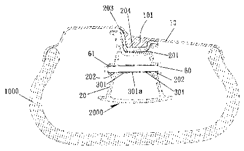
Referring to FIGS. 1, a wheel rim assembly in accordance with the
present invention is shown comprised of a wheel rim body I0, and a
supplementary tire support 2000 mounted around the periphery of the wheel rirn
body 10. 'The wheel rim body 10 comprises a flange 101 extended around the
periphery on the middle (see FIG 1). The cross section of the flange 101 can
be
made having any of a variety of shapes.
Referring to FIG 2 and FIG 1 again, the supplementary tire support
2000 is comprised of a plurality of joint blocks 20, a plurality of links 30,
a first
end connecting member 40, a second end connecting member 40a, and a screw
bolt 50.
The joint blocks 20 are hollow block members (see FIGS. l and 2;),
each having a top recess 201 fixedly mounted with a packing pad 203, and two
through holes 202 axially aligned at two opposite lateral sides. The packing
pad
203 has a recessed portion 204 fitting the flange 101 of the wheel rim body
10.
2
CA 02516127 2005-08-17
The bottom side of each joint block 20 has a rhombic shape (see FIG 5).
The links 30 connect the joint blacks 20 in series, each comprising a
front barrel 301a transversely disposed at the front side, two rear barrels
3031
transversely aligned at the rear side, and an arched bearing portion 30:>.
transversely disposed at the rear side and connected between the rear barrels
30~f
(see FIG 3).
The first end connecting member 40 and the second end connecting
member 40a are connected together to join the ends of the series of joint
blocks
20 (see FIG 4). The first end connecting member 40 comprises a U-shaped base
frame 402, two transverse barrels 401 respectively fixedly provided at the
ends
of the U-shaped base frame 402, and a through hole 403 extended through the
middle part of the U-shaped base frame 402 (see FIG 4). The second end
connecting member 40a comprises a base frame 402a, a barrel 401 fixedly
transversely provided at the front side of the base frame 402a, a screw hole
403;a
axially defined in the rear side of the base frame 402a, and a pin hole 404
formed in one lateral side of the base frame 402a (see FIG 4).
The screw bolt 50 is inserted through the through hole 403 of the fin~t
end connecting member 40 and threaded into the screw hole 403a of the second
end connecting member 40a to secure the first end connecting member 40 and
the second end connecting member 40a together, having a polygonal shoulder
501 for the grasping of a wrench or the like that is used to drive the screw
bolt
50 into the screw hole 403a of the second end connecting member 40a and a
series of transverse pin holes 502 (see FIG 4). A pin 503 is inserted through
the
pin hole 404 of the base frame 402a of the second end connecting member 40a
into one pin hole 502 of the screw bolt 50 to lock the screw bolt 50 to the
3
CA 02516127 2005-08-17
second end connecting member 40a.
Referring to FIGS. 1-~4 again, by means of connecting the barrels
301;301a of the links 30 and the barrels 401;4fl1a of the end connecting
members 40;40a to the through holes 202 of the joint blocks 20 with screw
bolts
60, the rim support 200 and the joint blocks 20 with the links 30 and the end
connecting members 40;40a are fastened together, thereby forming the desired
supplementary tire support 2000 around the periphery of the wheel rim body IID
within the tire 1000. After insertion of the screw bolt 64 into the through
holes
202 of one joint block 20 to connect the rear barrels 301 of one link 30 to
the
front barrel 301a of another link 30 transversely disposed at the front side,
two
rear barrels 301, a pin 61 is fastened to a pin hole G0a in the rear end of
the
screw bolt 60 to secure the screw bolt 60 to the respective joint block 20.
Referring to FIG 6, the supplementary tire support 20fl0 is mounted
inside the tire 1000, and then the wheel rim body 10 is inserted into the
inside o~f
the tire 1000 and fixedly fastened to the tire 100fl, and then the hand is
inserted
into the tire 1000 to push the supplementary tire support 2000, forcing the
recessed portion 204 of each joint block 20 into engagement with the flange
101
of the wheel rim body 10 (see FIGS. l, 2 and 6), and then the screw bolt SO is
inserted through the through hole 403 of the first end connecting member 40
and
threaded into the screw hole 403a of the second end connecting member 40a
and fastened tight with a wrench to afl-ix the supplementary tire support 2000
to
the flange I01 of the wheel rim body 10, and then the pin 503 is inserted
through the pin hole 404 of the base frame 402a of the second end connecting
member 40a into one pin hole 502 of the screw bolt 50 to lock the screw bolt
50
to the second end connecting member 40a.
4
CA 02516127 2005-08-17
Referring to FIG 7, when the tire 1000 is broken, the supplementary
tire support 2000 support the broken tire 1000, enabling the driver to drive
the
car to a vehicle repair shop for repair.
Although a particular embodiment of the invention has been described
in detail for purposes of illustration, various modifications and enhancements
may be made without departing from the spirit and scope of the invention.
Accordingly, the invention is not to be limited except as by the appended
claims.
5