Note: Descriptions are shown in the official language in which they were submitted.
CA 02516287 2007-05-29
1
CARGO LOCK AND MONITORING
APPARATUS AND PROCESS
FIELD OF THE INVENTION
This invention is directed towards a security device and monitoring
process. The apparatus and process is adaptable for a wide number of asset
tracking processes and procedures, including cargo containers. In one
embodiment of the invention, a locking member for a 55 gallon drum is provided
which secures the drum lid against unauthorized access and removal. The drum
locking mechanism may be further equipped with a customized selection of
sensor options including chemical sensors, radiation detectors,
accelerometers,
tilting switches, temperature sensors, and various tamper monitors. Further,
the
locking mechanism includes additional tamper resistant housings which may
contain power sources, global positioning satellite (GPS) tracking components,
wireless two-way communication components, along with a microprocessor.
The microprocessor may be used to engageldisengage the locking member as
well as coordinate the operation of the additional electronic components.
BACKGROUND OF THE INVENTION
This invention relates to an asset tracking system and devices which
provide positional and sensory data for cargo, vehicles, and other objects.
Cargo
monitoring capabilities are known such as that disclosed in U.S. Pat. No.
6,529,141 directed to a vehicle tracking and monitoring system using GPS
technology and communication equipment to monitor assets for pre determined
alarm conditions.
DOCSOTT: 563332\1
CA 02516287 2005-08-10
WO 2004/077686 2 PCT/US2004/005307
WIPO Publication WO 03/032501 is directed to an asset-tracking
system using a network of radio transceivers. Assets which can be monitored
are stated to include shipping and warehoused cargo.
U.S. Pat. No. 5,887,176 describes a process of automated inventory
interrogation using remote sensors to assist in inventory monitoring.
U.S. Pat. No. 6,055,426 describes a mobile cargo unit having a
telecommunications package including a GPS module which provides
notification when a mobile cargo unit is out of a coverage area. The system
configuration facilitates the storage and delayed transmission of information
1o when the mobile cargo unit re-enters a coverage area.
U.S. Pat. No. 6,512,478 is directed to a system of radio frequency (RF)
tags in association with nearby relay stations to monitor and track various
assets such as a manufacturer's inventory, airport luggage, or similar items
within a defined relay coverage area.
While numerous techniques and devices are used to monitor and track
a variety of assets, there remains room for variation and improvement within
the art.
SUMMARY OF THE INVENTION
It is one aspect of at least one of the present embodiments to provide
for a security apparatus which may be used to monitor a cargo container.
One such application includes a closure locking apparatus for securing a lid
to
a drum or barrel.
It is yet another aspect of at least one embodiment of the present
invention to provide for a drum locking apparatus which prevents removal of a
drum lid from the drum. The drum locking apparatus provides for a physical,
locked engagement with the lid to prevent the removal of the lid from an
associated drum. The locking mechanism is preferably provided by one or
more solenoid-controlled tabs which are used to selectively engage and
release a sliding member which, when engaged in a locked position, prevents
the removal of the drum lid and locking apparatus from the drum. A
microcontroller, responsive to external encoded signals, is used to
selectively
engage and disengage the solenoid tabs. Additionally, the drum locking
CA 02516287 2005-08-10
WO 2004/077686 3 PCT/US2004/005307
apparatus may contain a GPS transponder; a wireless two-way
communication suite; and one or more sensors used to monitor the cargo.
An additional aspect of at least one embodiment of the present
invention is directed to a cargo security unit which is in physical contact
with a
cargo drum, shipping pallet, or other packaging container. The cargo security
unit has within a sealed interior a GPS transponder, wireless two-way
communication suite, a battery, microcontroller and one or more sensors
designed to interact with a monitoring system. The cargo security unit, when
placed on a package or other asset, provides real time sensory and GPS
1o data/mapping information which may be transmitted to and monitored by a
command center. Sensors provided within the cargo security unit ideally
include physical data sensors which would register unauthorized attempts to
move, tamper, or destroy the associated package/asset.
An additional aspect of at least one embodiment of the present
invention provides a coordinated, multi-functional system to cargo protection
and monitoring. In the transportation industry, the technology of and ability
to
use global positioning satellite (GPS) technology to monitor and track
movement of a truck or other vehicles is well known. However, GPS tracking
of a vehicle offers no information as to the integrity of the cargo, including
containers or packages which may be carried within the vehicle. For instance,
cargo theft, cargo damage, or tampering with cargo which occurs during
transport may not be noticed until the vehicle reaches its final destination.
Accordingly, an apparatus and monitoring system is provided which
facilitates the monitoring of an individual cargo container or similar asset
and
which can be monitored independently of any existing vehicle monitoring
system. The ability to monitor an individual package or unit within a vehicle
offers several advantages. For instance, hazardous cargo such as nuclear
materials, hazardous waste, or other toxic materials is frequently packaged in
large drums such as 55 gallon drums. The security and integrity of such
cargo shipments has been given greater emphasis since hazardous cargo
can be misused as a weapon in a terrorist attack.
Further, in the event of a vehicle accident involving a hazardous cargo
shipment, there is a need to coordinate accident response teams and provide
the response teams with real time telemetry and security data as to the cargo
CA 02516287 2005-08-10
WO 2004/077686 4 PCT/US2004/005307
and the integrity of the cargo contents. In embodiments of the present
invention which employ a locking apparatus as part of the cargo security,
there may arise a need to disengage the locking apparatus to assist on-scene
recovery personnel. Likewise, the ability to monitor remotely in real time
individual cargo packages allows an immediate response should unauthorized
tampering or removal be detected. As set forth below, one embodiment of the
present invention permits the real time monitoring of cargo while providing an
additional mechanical locking apparatus for preventing or delaying entry into
the secured package.
These and other features, aspects, and advantages of the present
invention will become better understood with reference to the following
description and appended claims.
BRIEF DESCRIPTION OF THE DRAWINGS
A fully enabling disclosure of the present invention, including the best
mode thereof to one of ordinary skill in the art, is set forth more
particularly in
the remainder of the specification, including reference to the accompanying
drawings.
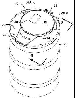
Figure 1 is a perspective view of an embodiment of the drum locking
apparatus securing a drum lid to an associated drum.
Figure 2A is a schematic view of the drum lock apparatus seen in
Figure 1, setting forth operational details and electronic components of the
locking mechanism.
Figure 2B is a detailed view in partial section of a locking mechanism
seen in an engaged position.
Figure 3 is a sectional view taken along line 3-3 of Figure 1 illustrating
the location of a tamper switch with respect to the drum lid and locking
apparatus.
Figure 4 is a schematic view of integrated electronic system
components which may be used with a drum lock apparatus.
Figure 5 is a schematic view of a system incorporating a container lock
apparatus which provides for remote two-way communication and positional
information to be transmitted to a monitoring station.
CA 02516287 2005-08-10
WO 2004/077686,.. PCT/US2004/005307
Figure 6 is a perspective exploded view of an alternative embodiment
of a security apparatus which may be attached to a drum, cargo package, or
other transportation asset.
Figure 7 is a perspective view of an additional embodiment of a
5 security apparatus which may be attached to a commercial cargo asset.
DESCRIPTION OF THE PREFERRED EMBODIMENT
Reference will now be made in detail to the embodiments of the
invention, one or more examples of which are set forth below. Each example
is provided by way of explanation of the invention, not limitation of the
invention. In fact, it will be apparent to those skilled in the art that
various
modifications and variations can be made-in the present invention without
departing from the scope or spirit of the invention. For instance, features
illustrated or described as part of one embodiment can be used on another
embodiment to yield a still further embodiment. Thus, it is intended that the
present invention cover such modifications and variations as come within the
scope of the appended claims and their equivalents. Other objects, features,
and aspects of the present invention are disclosed in the following detailed
description. It is to be understood by one of ordinary skill in the art that
the
present discussion is a description of exemplary embodiments only and is not
intended as limiting the broader aspects of the present invention, which
broader aspects are embodied in the exemplary constructions.
In describing the various figures herein, the same reference numbers
are used throughout to describe the same material, apparatus, or process
pathway. To avoid redundancy, detailed descriptions of much of the
apparatus once described in relation to a figure is not repeated in the
descriptions of subsequent figures, although such apparatus or process is
labeled with the same reference numbers.
As best seen in reference to the accompanying figures, an apparatus
3o and process is described with respect to one embodiment of a cargo locking
apparatus and process. As seen in Figures 1 and 2, a locking apparatus 10
is provided which, in the illustrated embodiment, is adapted for engaging a
cargo drum 20 along with a secured lid 22. The drum locking apparatus 10
defines an upper panel 12 and a lower panel 14. A first housing 30 is defined
CA 02516287 2005-08-10
WO 2004/077686 6 PCT/US2004/005307
between the upper panel 12 and the lower panel 14. A second housing 50 is
additionally defined between panel 12 and panel 14, an internal dividing wall
52 separating housing 30 from housing 50.
The locking apparatus 10 may be provided by either a metal
construction such as stainless steel, or constructed from plastic. Most
plastics
are transparent to electronic transmissions, thereby enabling the entire
communications suite to be sealed inside a housing provided for the
electronics's bay. This characteristic of plastic eliminates the need for any
exposed antennas. Additionally, plastic offers greater manufacturing
1o economy for large production runs through techniques such as injection
molding. Further, for cargo which may include hazardous chemicals or
radioactive materials, accidents and spillage may occur as some point. A
plastic locking apparatus offers a sealed, liquid, and vapor impervious
housing
which protects the electronic components therein. The locking apparatus may
be more easily decontaminated or, if impractical, the sealed electronic
package may be removed for use in a newly constructed unit.
The embodiment of Figure 1 sets forth a locking apparatus 10 that
defines a series of flanges 32A and 32B seen as extensions of lower panel
14. There is a spaced region between flanges 32A and 32B in which a
conventional drum lock mechanism such as a combination securement ring
with lug nut 24 may be positioned. A third flange, referred to as locking
flange
34, is illustrated as equidistant between flanges 32A and 32B. As illustrated,
the flanges 32A and 32B along with locking flange 34 define a "Y" shaped
structure in which the lower portion of the "Y" defines the locking flange 34.
As seen in reference to Figure 2B and Figure 3, a terminus of each arm
32A/32B and locking arm 34 defines a rolled arcuate outer edge terminus 33
which is adapted for engaging a corresponding shaped arcuate edge of a
drum 20 with secured lid 22. As best seen in reference to Figure 2A, each
terminus 33 defines a lower rolled lip edge 35 which is positioned beneath the
main body portion of the respective flanges 32A, 32B, and 34. The lip 35 and
arcuate shape of the terminus 33 is adapted for engaging the upper rim of the
drum 20 when lid 22 is attached. The particular shape of the terminal edge,
along with the degree of curvature of the outer perimeter of the various arms,
CA 02516287 2005-08-10
WO 2004/077686 7 PCT/US2004/005307
may be modified as needed to form the desired engagement with the edge of
a particular sized drum or container shape.
As further seen in reference to Figure 2A, the respective flanges 32A,
32B, and 34 may define an edge profile which varies over a length of the
flange. As seen, the variations in edge profile allows the respective flanges
to
conform to any corresponding surface profile changes of the drum lid 22. In
this manner, the respective flanges can conform to the surface of the drum lid
and thereby provide an improved, more secure attachment of the drum lock
apparatus 10.
One having ordinary skill in the art will recognize that a wide variation
in the number and shape of flanges may occur. Such variations may include
embodiments where the entire perimeter of the drum lock apparatus defines
an engaging flange to embodiments where four or more flanges may be used
(Figure 6). Where multiple flanges are used, it is also envisioned that more
than one locking flange may be provided. The locking flange is described
below in detail in reference to a single locking flange 34.
As best seen in reference to Figures 2A and 2B, locking flange 34 may
occupy a first locked position in which flange 34 is secured by one or more
locking solenoids 60. Tabs 36 which project downward from a surface of
flange 34 defines at least one aperture for receiving an engaging member
defined by a moveable piston of the solenoid(s) 60. When the locking piston
end 62 of solenoid 60 is engaged through the aligned aperture 39, defined by
tab 36, flange 34 is maintained in the engaged, locked position.
As best seen in reference to Figures 2A and 2B, locking flange 34 may
be positioned between the engaged and disengaged position by the tabs 36
which slide between openings 38 defined along a raised edge 37 of lower
panel 14. When flange 34 is placed in operative engagement with the outer
rim of the drum 20/lid 22, a corresponding aperture 39 defined by tabs 36 is
positioned opposite the engaging locking pin 62 of solenoid 60. As seen in
3o reference to Figure 2A, solenoid 60 is held in position within housing 50
through attachment to a mounting ciip 64. Clip 64 defines a pair of aligned
apertures 66 through which locking pin 62 may extend when engaging tab 36
and aperture 39 in a locked position.
CA 02516287 2005-08-10
WO 2004/077686 8 PCT/US2004/005307
When apparatus 10 is locked in position upon a storage/shipping drum
20 with lid 22, the drum lock apparatus 10 prevents removal of the lid 22 from
the drum 20. The activation/deactivation of the solenoid lock 60 with tabs 36
may be controlled by the keypad 40 (Figure 1) and which may also include a
display screen, in communication with an associated microcontroller 42. The
interaction of the keypad 40, microcontroller 42, and other electronic
components of the locking apparatus is described below in greater detail.
As seen in reference to Figure 3 and in the alternative embodiment of
Figure 6, a tamper switch 90 may be provided on the underside of locking
1o apparatus 10 or security apparatus 10'. The tamper switch 90 may be in the
form of a simple plunger-actuated device which detects when the apparatus
10/10' is engaged on a surface of a drum or other cargo asset. Other forms
of a tamper switch 90 may be provided such as a proximity sensor, a light
sensor, or a magnetic sensor among others. Should the locking apparatus 10
or security apparatus 10' be removed from the container, the tamper switch
90 provides a signal to the associated microprocessor 42 that the unit 10/10'
has been removed.
Depending upon the selected programming of the microprocessor and
control functions, the activation of the tamper switch may be used to trigger
a
silent alarm signal sent to a remote command center as better described
elsewhere in this application. In addition to or, in the alternative, an
audible
alarm located on the unit 10/10' may be actuated. Subsequent actions via the
command center may include alerting a driver or other personnel
safeguarding the cargo and/or alerting local law enforcement agencies.
The dimensions of standard size drum containers include 85, 55, 30,
15, 10, 5, and 1 gallon drums. The dimensions are uniform within the industry
and simplifies the proper construction, shape, and dimensions for
securement of the locking flange or other attachment mechanism. When
engaged, locking apparatus 10 prevents unauthorized access to the drum's
contents. Further, with optional sensors described below, the drum lock
apparatus 10 may be configured to provide security alerts in the event of
cargo tampering or theft.
The components of one embodiment of the drum locking apparatus
embodiment as seen in reference to Figure 2A comprises the physical
CA 02516287 2007-05-29
9
structure with flanges for engaging a container. In addition, the housing
contains
a battery 44, a system computer or microcontroller 42, a GPS antenna 45, a
solenoid 60 responsive to the microcontroller 42, and a radio frequency
transmitter/receiver unit 46. Optionally, status lights 47 may be used to
indicate a
lock/unlock condition of the apparatus 10 and/or to provide a low battery
alert
signal. In addition, an audible alarm 49 may be included as a component along
with one or more sensors 80 and additional components as referenced in Figure
4.
The various components illustrated in Figure 4 set forth certain optional Jo
items which may be included within a drum lock apparatus 10 or security
apparatus 10'. Depending upon the level of required security and cost, the
various components may be selected and combined to achieve various
embodiments, certain ones of which are discussed in detail herein.
With respect to the electronic components and interactions set forth in I
Figures 4 and 5, the ability of the various electronic components mentioned
herein all require some form of a physical or wireless interconnectivity and
communication. Such interactions are shown in a schematic form and, for the
purposes of.clarity of the Figures, is not provided in detail. The operation
of the
various components is known as set for the in the following U.S. patents.
These
patents include U.S. Pat. Nos. 6,529,141; 6,055,426; 6, 512,478; 6,542,114;
and
WIPO Publication WO 03/032501.
As is well know in the art, the RF receiver/transmitter 46 may be used to
receive and/or transmit low frequency transmissions. Other forms of wireless
communication components may also be included which operate in accordance
with BluetoothT"" standards. However, any wireless transceiver having the
capability to communicate with other wireless transceivers such as Home RF,
infrared devices, Ethernet transceivers and others may be used. The RF
transceiver tag or equivalent communication device uses established so
encryption and communication protocols to communicate with the microcontroller
42 and a remote monitor unit 70 (Figure 5).
As best seen in reference to Figure 2A, a numeric keypad 40 may be
provided in which a lock/unlock code may be entered. Alternatively, a
communications port 41 for use with a portable microcontroller may be used.
DOCSOTT: 563332\1
CA 02516287 2005-08-10
WO 2004/077686 10 PCT/US2004/005307
The keypad operation is controlled by a microprocessor 42 which is mounted
in a housing defined between the upper panel 12 and the lower panel 14. A
battery 44, such as a lithium or long-life rechargeable battery, is also
provided
which powers the operation of the keypad, microprocessor, solenoid, and any
other electronic hardware which may be included within the locking apparatus
10. When rechargeable batteries are used, a recharging port may be
provided which can recharge the batteries without disassembling the locking
apparatus unit.
For metal embodiments, a keypad or communication's port is desired
1o to allow input of commands to the microcontroller. Embodiments of a plastic
security apparatus 10' (Figures 6 and 7), are largely transparent to various
forms of wireless communication, and do not require a keypad or any
exposed electronic components for operation. Rather, all the electronic
components including a wireless receiver may be contained within one or
more sealed housings defined by the apparatus 10'.
As further seen in reference to Figures 6 and 7, alternative
embodiments of the invention are provided in the form of a security apparatus
10'. As seen in reference to the electronic schematic of Figure 4 and the
details of Figures 6 and 7, the security apparatus 10' may further define a
wireless modem 58; a GPS transceiver 45; an audible alarm 49; and an
expandable array of sensors 80. Available sensors may include, among
others, radiation detectors, temperature detectors, motion sensors, vibration
sensors, accelerometers, tilt switches, chemical sensors, or fire/smoke
sensors. While many of the functional electronic and communication
components are identified as physically separate items, it is readily
appreciated and understood by one of ordinary skill in the art that a single,
multifunctional unit may be provided which combines multiple functions.
As seen in reference to the embodiment illustrated in Figure 6, a
security apparatus 10' can be provided which does not utilize a remote
locking/unlocking feature. Instead, the security apparatus 10' relies upon a
series of internal sensors along with a manual engagement to the container
which prevents removal of the container's lid.
As illustrated in Figure 6, an upper panel 12 and a lower panel 14
define a housing 30 therebetween in which an array of electronic components
CA 02516287 2005-08-10
WO 2004/077686 11 PCT/US2004/005307
.. . _._
(as previously described) may be installed in operative and cooperative
engagement. Alternatively, a single panel member can be provided which
provides an integral housing which may contain the electronic components.
Positioned beneath panel 14 is a tamper switch 90. A series of engagement
members 13 such as screws, rivets, or bolts are used in association with
washers 15 to secure panel 12 and panel 14 together. A metal sleeve 16 may
be positioned along apertures defined within the respective panels 12 and 14
for receiving engaging members 13. Engaging members 13 are preferably in
the form of a tamper resistant threaded fastener which requires a special
service tool to install or remove.
While engaging members 13 is illustrated as being installed from an
upper surface of security apparatus 10', the engagement members 13 can
also be installed from a lower surface of apparatus 10'. Such positioning of
the members 13 may provide additional resistance to tampering with security
apparatus 10' when the apparatus is installed on a container as described
below.
Security apparatus 10' defines a series of arm-like extensions of panel
14 which may project in part beyond the upper surface of the cargo unit such
as drum 20 having lid 22. A plurality of retention flanges 134 are defined
2o along the terminus of each extension. A portion of flange 134 may extend
beyond the surface of the drum 20/lid 22 and provide an attachment site for a
corresponding bracket 100. Bracket 100 is secured to the lower surface of
flange 134 and may use similar engagement members 13, washers 15, and
sleeves 16 as previously described. The attachment hardware is inserted
through openings 17 defined within bracket 100. Alternatively, a bracket 100
may be provided as a unitary construction such as an injection molded plastic.
The bracket 100 may be attached to either an outer edge of corresponding
flange 134 or to the lower flange surface as illustrated.
Bracket 100 defines an innermost lip 112 which is formed in part by a
tapering inner surface 114 of bracket 100. Lip 112 engages the lower rim of a
drum 20/lid 22 container and prevents the removal of the lid 22 from the drum
20. As seen in reference to Figure 6, bracket 100 may have the inner and the
outer edges in the form of an arcuate shape configured to the dimensions of
the upper container's perimeter edges. As illustrated, this embodiment of the
CA 02516287 2005-08-10
WO 2004/077686 12 PCT/US2004/005307
security apparatus 10' is placed and secured to the cargo container through
the engagement of brackets 100 to the flange 134. Upon arrival of the cargo
at a destination, the bracket 100 can be removed, allowing normal access to
the drum 20 and lid 22.
While the embodiment seen and described in relation to Figure 6 does
not provide for a remote locking/unlocking capability, the security apparatus
10' does provide for a physical securement of the lid to the drum when
installed. An unauthorized effort to remove the security apparatus 10' or gain
access to the container will trigger one or more of the sensors 80 contained
1o within the security apparatus 10'. Further, tamper switch 90 provides an
additional monitoring function should the security apparatus 10' be removed
from the container.
Alternatively, the security apparatus 10' may be provided in an
embodiment in which at least two flanges and two brackets are present. The
dimensions of the flange arms and associated brackets are such that when
positioned onto an appropriate sized drum, applied pressure will snap-fasten
the apparatus 10' onto the drum20/1id22. A suitably tight fit may be
established such that considerable force is required to unfasten the apparatus
10' from the drum 20. Such removal efforts are detected by the associated
sensors. An embodiment have three fixed position arms and engaging
structure similar in appearance to the embodiment seen in Figure 1 may be
provided. Such an embodiment may be installed by positioning two of the
arms in an engaged position whereby the third arm is pressed downwardly.
The pressure forces the third arm and appropriate lip/bracket over the drum
rim, thereby "locking" the security apparatus and lid 22 onto the drum.
An additional embodiment of a security apparatus 10' is seen in
reference to Figure 7. In this embodiment, the security apparatus 10' has an
upper panel 12 and a lower panel 14 defining a housing therebetween. As set
forth in the previously described embodiments, a variety of electronic
components, including sensors, communication devices, and tamper switches
may be incorporated into the construction of the security apparatus 10'. The
perimeter of security apparatus 10' defines a plurality of apertures 217 which
may be used to secure the security apparatus 10' to a cargo asset using
similar attachment hardware as described above in reference to the
CA 02516287 2005-08-10
WO 2004/077686 13 PCT/US2004/005307
embodiment of Figure 6. Alternatively, other forms of mechanical attachment
may be used including semi-permanent installations using ultrasonic welding,
thermoset adhesives, or similar techniques. Preferably, security apparatus
10' has the central housing formed of an electromagnetically transparent
plastic. The housing defined between upper surface 12 and lower surface 14
is preferably sealed against liquid and vapor. While the embodiment of Figure
7 does not provide for a physical locking mechanism for preventing access to
the cargo container, upon appropriate selection of sensors, the security
apparatus can provide an alert mechanism should unauthorized tampering
occur.
While not separately illustrated, a suitable security apparatus 10' may
be provided which is integral with an existing drum lid 22. In such an
embodiment, a housing can be provided on the upper surface of drum lid 22
which contains the various electronic components, communication devices,
and sensors. As such, the normal securement mechanisms such as a
compressive fit and/or a lug bolt securement ring can be used to provide
physical engagement between the lid 22 and the drum 20. When lid 22
physically incorporates the necessary housing and electronic hardware,
sensors and other communication hardware within the housing will provide a
warning alert should tampering of the container occur.
While the embodiment of Figure 7 is shown attached to a cargo drum,
it is readily appreciated that the security apparatus 10' could be attached to
a
variety of cargo packaging materials including pallets, boxes, cartons, or
cargo pods. The security apparatus sensors and communication arrays allow
for an electronic barrier to be associated with individual cargo assets. Upon
selected, monitored conditions, an appropriate alarm notification may be sent
to a remote command center. The alarm notification may include the
activation of an optional audible alarm feature contained within security
apparatus 10'.
While not separately illustrated, any of the embodiments of the locking
apparatus or security apparatus described herein may have a battery charger
port associated therewith to permit recharging of the battery. Alternatively,
solar regenerative charging or a vibratory charging mechanism may be
provided to recharge the battery or otherwise replenish a power source. In
CA 02516287 2005-08-10
WO 2004/077686 14 PCT/US2004/005307
addition, while the drum locking apparatus 10 and security apparatus 10' have
been described as a separate component for use with a container, it is readily
understood and appreciated that a drum lid 22 could be constructed in which
a drum lock apparatus 10 or security apparatus 10' may be an integral part of
the lid 22. For instance, a surface of lid 22 may define the lower panel 14 to
_
which an upper panel 12 is attached.
As best seen in reference to Figure 5, the cargo lock apparatus 10 or
security apparatus 10' may be one component in a monitoring/relay system.
An additional system component includes a monitor unit 70 as seen
1o positioned along a ceiling area of a cargo trailer. The illustrated system
recognizes the fact that typical cargo containers are metallic which inhibits
GPS transmissions. Positioning the monitor unit 70 outside the cargo
container allows for proper GPS send/receive. Communication between
monitor 70 and drum locking apparatus 10 and/or security apparatus 10' may
make use of RF transmission/receive communication devices which are not
typically inhibited by metal. The monitor unit 70 provides a communication
link between the individual container lock apparatuses 10 or security
apparatus 10', a remote command center 74, and orbiting Global Positioning
Satellite 76. The monitor unit has a GPS transponder, microcontroller and a
secure wireless communication package designed to transmit and receive
data and commands from a remote command center to the container lock unit
10/security apparatus 10' in proximity to the monitor unit. It is through the
monitor unit that the security access (lock/unlock), proximity alarms, various
sensors, electronic manifest data and various operational parameter rules and
communications are transmitted and controlled. Communications from the
command center to/from the monitor unit 70 may include cellular, satellite, or
other forms of wireless, secure communication. Such communication
protocols and equipment which provide secured communication are well
known in the art.
The command center 74 remotely tracks and manages the container
lock apparatus 10/security apparatus 10' and associated cargo. Using
established GPS mapping and tracking software, real time positional
information can be gathered and tracked. Further, data collected by the
sensors 80 of the individual apparatuses 10/10' can be monitored. Through
CA 02516287 2005-08-10
WO 2004/077686 15 PCT/US2004/005307
the command center, instructions and alarm conditions can be relayed
through monitoring unit 70 to the individual container lock unit 10/security
apparatus 10'.
For instance, in the illustrated example of Figure 5, a truck's cargo can
be outfitted with the monitoring system components described herein. The
command center will receive periodic updates of GPS and sensor information
for either drum lock 10 or security apparatus 10' on a reporting schedule
which may be adjusted as needed by instructions issued from the command
center. The driver can inform the command center of meal breaks or
1o overnight stops which provide the command center the option of changing
reporting protocols, such as frequency. In addition, the reporting protocols
may also be changed to set new alarm report thresholds for GPS or sensor
data.
For example, where the cargo transit is halted for an overnight stop,
the alarm conditions may be established such that any GPS detected
movement triggers an alarm report to the command center. Similarly, motion
sensors, tilt sensors etc., can also have an increased sensitivity threshold
established so that even a low threshold of detection will be transmitted as
an
alarm condition to the command center. From the command center, sensory
2o and reporting data can be monitored with appropriate follow-up action such
as
local law enforcement contact an/or establish contact with the driver for
further
investigation.
Through the command center 74, the container lock unit 10/security
apparatus 10' can be programmed to signal an alert should there be deviation
from an accepted transportation route. Should the cargo fall outside of an
accepted transit location with associated timelines, an alarm feature will be
activated signaling the command center of a possible alarm condition. Such
functions are reprogrammable during transit such that delays caused by
weather, traffic conditions, or mechanical problems may be incorporated into
3o a new route and timeline program.
In the case of potentially hazardous materials such as radioactive
materials or hazardous chemical inventories, enhanced reporting and
monitoring can be implemented at any time. For instance, during times of
CA 02516287 2005-08-10
WO 2004/077686 16 PCT/US2004/005307
heightened security alerts, more frequent monitoring protocols of sensitive
cargo may be initiated.
Other useful scenarios include shipments of perishable goods such as
those requiring refrigeration. A temperature sensor could provide advance
warning of a compressor or other refrigeration equipment failure associated
with a cargo shipment. As a result, an appropriate detour or repair may be
initiated which may prevent the loss of a perishable cargo.
The command center can make available to customers/subscribers,
real time access to data via a secure internet connection. Typically, an
internet connection is a "monitor only" viewing platform without an ability to
directly interact with the system parameters. In this manner, a customer may
monitor appropriately tagged cargo and may communicate with the command
center if needed. Actual control of the locking or security apparatus 10/10',
monitoring unit 70 and command center 74 resides at all times with the
operators within the command center. Additionally, the command center may
issue routing reports or alerts to designated customers or subscribers via
cell
phone, pager, or e-mail.
The tracking and monitoring of a secure cargo package offers greater
flexibility when three operational components are present. These operational
components include the container lock apparatus 10 and/or security
apparatus 10', a monitor station 70 associated with a cargo carrier or
warehouse, and a remote command center 74. The container lock apparatus
and associated communication devices have been described above. For
many applications, it is desirable that the container lock apparatus 10 be
subject to remote monitoring and control. For instance, in case of an accident
or emergency, a remote command center may be used to remotely unlock the
container lock apparatus, deactivate alarm functions, or take other action to
assist local authorities or emergency response teams.
In instances where electronic communication between the container
lock apparatus 10 or security apparatus 10' and the remote call center is
possible, the remote call center may use satellite or cellular communications
to establish contact and command authority over the container lock
apparatus. More commonly, the shipping and cargo transit requirements are
such that direct lines of communication between a container lock apparatus
CA 02516287 2005-08-10
WO 2004/077686 17 PCT/US2004/005307
and a remote call center are unreliable given interference from a cargo
trailer,
pod, or warehouse. To address these issues, a local monitoring unit 70 may
be provided as seen in reference to Figure 5. The monitoring unit 70 is
placed in close proximity to the cargo having a container lock apparatus 10 or
security apparatus 10' and provides a reliable communication and control
node between the container lock apparatus and a remote command center.
The monitoring unit 70 may include a GPS module to allow tracking and
monitoring of the cargo via the GPS transceiver in the container lock
apparatus. This connection allows the remote command center to monitor the
1o position and movement of the individual cargo units having the container
lock
apparatus.
Optionally, the monitoring units provide two-way communication
capabilities with the container lock apparatus 10 or security apparatus 10'
through a device such as a radio frequency (RF) receiver/transmitter 46 which
may receive and send information to and from the monitoring unit.
The monitoring unit 70 provides enhanced communications capability
between the remote call center and the container lock apparatus 10 or
security apparatus 10'. As such, the remote command center may, via the
monitoring unit, send and receive information to and from the apparatus
10/10'. Using well established communication and security protocols, the
remote command center may issue instructions to lock/unlock the container
lock apparatus 10, may monitor the sensor data of the container lock
apparatus10 or security apparatus 10', may monitor the GPS telemetry data
from individual apparatuses 10/10', receive alarm conditions should an
apparatus 10/10' be removed from an authorized location or deviate from an
accepted route.
The present system provides a powerful tool for real time data
acquisition and management of assets protected with the container lock
apparatus. For instance, a driver of a cargo vehicle can call a command
station to indicate that he is "going stationary" for a meal break.
Accordingly,
the container lock or security apparatus 10/10' can be programmed to provide
immediate alarm notification should any motion or movement be detected via
the GPS transponder or other sensors. Following a meal break, the driver
can again contact the remote command center to indicate that normal travel
CA 02516287 2005-08-10
WO 2004/077686 18 PCT/US2004/005307
will resume. Accordingly, the alarm communication parameters may be
changed to reflect the updated status of the cargo and cargo movements.
The remote command center facilitates multiple levels of interaction
and monitoring. For instance, with appropriate mapping software and
communications software, multiple authorized parties may track cargo
movement and conditions via internet monitoring.
Although preferred embodiments of the invention have been described
using specific terms, devices, and methods, such description is for
illustrative
purposes only. The words used are words of description rather than of
limitation. It is to be understood that changes and variations may be made by
those of ordinary skill in the art without departing from the spirit or the
scope
of the present invention which is set forth in the following claims. In
addition,
it should be understood that aspects of the various embodiments may be
interchanged, both in whole, or in part. Therefore, the spirit and scope of
the
appended claims should not be limited to the description of the preferred
versions contained therein.