Note: Descriptions are shown in the official language in which they were submitted.
CA 02516493 2005-08-18
WO 2004/074854 PCT/US2004/004196
RETURN PAD CABLE CONNECTOR
CROSS-REFERENCE TO RELATED APPLtCATtONS
The present application is a Continuation-in-Part of international Application
Serial No. PCT/US02/17360, filed May 31, 2002 which claims priority to U.S.
Provisional
Patent Application Serial No. 601295,176, filed June 1, 2001.
BAC~CGRt?UND
Technical Field
The present disclosure relates to a return pad cable connector and, more
particularly, to a return pad cable connector having a reusable cable
configuration and
adapted to rerr~ovably receive a disposable single use patient return pad.
Background ~f Related Arfi
Flexible conductive members (i.e., return pads, return electrodes, etc.) are
of
particular importance in the medical community wherein patients often need to
be
connected to electrical monitoring or electrical generating equipment. In such
applications,
flexible conductive members such as return pads or electrodes need to adapt to
the shape
1
CA 02516493 2005-08-18
WO 2004/074854 PCT/US2004/004196
of the patient's body in order to provide sufficient electrical contact with
the surface of the
patient's body.
Electrosurgery requires that an electrosurgical generator be connected to at
least two electrodes to produce and deliver an electrical potential to a
patient's body. For
exampf e, in monopolar electrosurgery, the electrodes usually consist of an
active electrode
applied at the surgical site and a return electrode or pad applied to a non-
surgical site on
the patient.
Generally, return electrodes are pliable and thus can be flexed or shaped to
meet particular application requirements. Return electrodes are usually
manufactured to
attach with a pressure sensitive adhesive directly to the surface of the
patient's body.
F2eturn electrodes are therefore designed and manufactured to be form fitting
orflexible so
as to p~'ovide adequate conductive contact with the non-flat surfaces of a
patient's body.
Typically a conductive adhesive is applied to the surface of the return
electrode to hold arid
~~~!!r~ ~~49~ r~ti~'rn el~,~i~r~~Ar;~ ~~ ti-~° '~'~ti~nt'~
~''°'°~~.
The return electrodes need to be electrically connected to the source
electrosurgical generator. This connection is usually provided by way of one
or more
insulated conductive wires which are configured to interface with the
electrosurgical
generator to complete the electrosurgicai circuit. fn the past, emphasis was
placed on
providing a tight physical connection between the conductive wire and the
return electrode
which could withstand potential disengagement of the conductive wire and
return pad
2
CA 02516493 2005-08-18
WO 2004/074854 PCT/US2004/004196
during a. surgical procedure.
Contemporary wire termination and connection methods usually require that
the ends of a wire be stripped of insulation, formed, and assembled to the
flexible
conductive member with a staple shaped attachment or some other attachable
fastener
such as a circular terminal and a rivet. The stripping process is highly
dependent upon the
nature of the insulation of the wire, the strip tooling design, and the
tooling setup. Wire
stripping problems can result in broken wire strands or wires that cannot be
formed or
terminated properly in subsequent operations. As can be appreciated, existing
terminating
and connection manufacturing pr~cesses tend t~ be overly complex and typically
require
tedious manufacturing steps to assure adequate electrical and mechanical
connections.
Inadequate electrical connections can result in impedance changes across the
tissue which
may effect the performance of the overall electrosurgical system.
in addition, for sanitary and medical reasons, after a return electrode (i.e.,
return pad) has been used in a medical far~cedure for a particular patient:,
the re~:~arn pad is
discarded and a ne~,~ reiurn pad is used for a new medical procedure for
either the same or
a different patient. Since return pads of the prior art are usually physically
coupled to the
conductive wire (i.e., hard wired), the conductive portion and generation
leads are
discarded along with the return pad. Typically, only the return pad needs to
be discarded
after each medical procedure for sanitary reasons. disposal of both the return
pad and the
conductive portion simply increases the costs associated with the medical
procedure.
3
CA 02516493 2005-08-18
WO 2004/074854 PCT/US2004/004196
Accordingly, the need exists for a return pad/electrode cable connector which
incorporates a disposable return pad which is removably coupled to a reusable
conductive
portion~connector.
SUMMARY
A return pad cable connector, in.accordance with the present disclosure, for
use with a disposable return pad, includes a cord having a conductive wire
disposed
therethrough which conductive wire interconnects the return pad cable
connector to an
electrosurgical energy source. The return pad further includes a connector
operatively
coupled to the cord, the connector having a conductive surface which is
selectively.
engageable with a corresponding conductive surface disposed on the return pad,
the
conductive surface of the connector including a conductive adhesive disposed
thereon and
a non-conductive adhesive disposed above the periphery of the conductive
surface of the
connector for engagement v~ith a corresp~nding n~n-c~nd~active adhesive
disp~sed ab~ve
the periphery of the conductive surface of the return pad.
A return pad cable connector, in accordance with a further embodiment of the
present disclosure, for use with a disposable return pad, includes a cord
having a
conductive wire disposed therethrough which conductive wire interconnects the
return pad
cable connector to an electrosurgical energy source and a connector
operatively coupled to
the cord. Preferably, an adhesive is provided on the connector, the return pad
or on both.
4
CA 02516493 2005-08-18
WO 2004/074854 PCT/US2004/004196
The connector includes at least one conductive surface which correspondingly
mates with
at least one conductive surface on the return pad. The conductive surface of
the connector
includes a border therearound fior engaging a border around the conductive
surface of the
return pad. The adhesive is provided on the conductive surface of the
connector, the
conductive surface of the return pad, the border surrounding the conductive
surface of the
connector andJor the border surrounding the conductive surface of the return
pad.
Preferably, at (east the adhesive provided on the conductive surface of the
return pad is a
conductive adhesive.
In still yet another embodiment, according to the present disclosure the cord-
to-pad connector includes a base element having a handle and a fiaced jaw
having a
conductive surface affia~ed to an inner surface thereof. A distal end of the
c~nductive wire
passes through the base element and operatively engages the conductive surface
of the
fixed jaw. The cord-to-pad connector further includes a return pad clamp
pivotally mounted
to the base element. The cord-to-pad connector is positionable between an open
position
yrhpr~i;~, i°ha rrp~~,rn pfd ''~°1~r3":p i~ ~'f~~~°d
~,~'ron~ '~l':° ~iat:~'~ j~~n! ~r;~ ~ ~!'i~'s~d p~~i~i~rl
m~rilZ°r~ie'l
the return pad clamp is in contact with the fixed jaw. Preferably, the return
pad clamp
includes a moveable jaw and a clamping lever depending Therefrom and extending
along
the handle which allows a user to selectively engage and disengage a return
pad.
preferably, the cord-to-pad connector further includes a locking mechanism
configured and adapted to selectively maintain the cord-to-pad connector in
the closed
position. The locking mechanism includes a latch projecting from the clamping
lever of the
CA 02516493 2005-08-18
WO 2004/074854 PCT/US2004/004196
return pad clamp and a locking rail projecting from a locking aperture formed
in the handle.
In use, the latch operatively engages the locking rail, thereby locking the
cord-to-pad
connector in the closed position.
Preferably, the return pad includes a pad-to-cord connector which has a
conductive pad surface disposed thereon which conductive pad surface is
configured and
adapted to operatively engage the conductive surface ofthe base element. In
this manner,
an electrical connection between the return pad and the cord-to-pad connector
is
established.
In an alternative embodiment, the return pad cable connector of the present
disclosure includes a cord having a conductive wire disposed therethrough
which connects
to an electrosurgical energy source and a connector anahich operatively
couples to the cord
wherein the connector has at least one magnet disposed thereon for
magnetically coupling
the connectorto a conductive surface disposed on the return pad. In accordance
with the
pr~v~i i~ dea'~'~a~,ohv~i~, w~.,-~~en t1';° ~~~n'~''W~ta~.ar I~
ri''ui~n~tiM~u~ ~~2~n'pi~~ ~n'~~e ti i~' ~'ra°n d'e~J~tiar'~ ~ui f~~~
disposed on the return pad energy is permitted to pass from the return pad to
the
electrosurgical energy source via the conductive wire.
Preferably, the at feast one magnet is made from an electrically conductive
material. 11/lore preferably, the conductive wire of the cord is electrically
coupled to the at
Least one eiectricaliy conductive magnet.
6
CA 02516493 2005-08-18
WO 2004/074854 PCT/US2004/004196
In an alternative embodiment, the connector further includes at least one
electrical contact disposed on the surface of at least one of the magnets.
Preferably, the
conductive wire of the cord is electrically coupled to each of the at least
one electrical
contacts.
In still an alternative embodiment, the connector includes a flexible
substrate
having a first portion and a second portion integrally connected to the first
portion, the first
and second portion defining a fold line therebetween and a magnet disposed on
each of
the first and second portions of the flexible substrate in order to sandwich
the conductive
surface of the return pad therebetween. Preferably, the conductive wire of the
cord is
electrically coupled to the magnet, such that when the connector is
magnetically coupled to .
the conductive surface disposed on the return pad, energy is permitted to pass
from the
return pad to the electrosurgical energy source via the conductive v~ire.
It is envisi~ned that at feast the magnet which is electrically coupled tca
the
conductive wire is made f'ror-n an electrically conductive material,
l~°referably, the connector
further includes at least one electrical contact disposed on the surface of
the magnet which
is electrically coupled to the conductive wire. The conductive wire of the
cord is preferably
electrically coupled to each of the at feast one electrical contacts.
it is envisioned that the conductive wire of the cord can extend from a side
of
the substrate which is either parallel to the fold line or transverse to the
fold line. It is
7
CA 02516493 2005-08-18
WO 2004/074854 PCT/US2004/004196
further envisioned that each magnet is coupled to the substrate via a pin
passing through
the magnet and into the substrate.
These and other advantages and features ofthe apparatus disclosed herein,
will become apparent through reference to the following description of
embodiments, the
accompanying drawings and fihe claims.
BRIEF DESCRIPTION OF THE DRAWINGS
The accompanying drawings, which are incorporated in and constitute a part
of this specification, illustrate embodiments of the invention and, together
with a general
description of the invention given above, and the description of the
embodiments given
below, serve fi~ explain the principles of the invention.
FIG. ~ is a bottom plan view of a return pad and an electrode cable connector
in accordance with the present disclosure;
FIG. ~ is a perspective view of a refiurn pad and an electrode cable
connecfior
in accordance with an alternafiive embodiment of the present disclosure;
FIG. 3 is a perspective view of a return pad and an electrode cable connector
in accordance with yet another embodiment of the present disclosure;
FIG. 4 is an exploded, perspective view of a return pad and an electrode
8
CA 02516493 2005-08-18
WO 2004/074854 PCT/US2004/004196
cable connector similar to the embodiments shown in FIG. 3;
FiG. 5 is a cross-sectional side eievational view of the electrode connector
of
FIG. 4 shown in the closed position;
FIG. 6 is a cross-sectional side elevationai view of the electrode connector
of
FiG. 4 shown in fihe open position;
F1G. 7 is a flop plan view of an electrode cable connector in accordance with
an alternative embodiment of the present disclosure;
FiG. ~ is a top plan view of an electrode cable connector in accordance with
bet another embodiment of the present disclosure;
F1G. 9 is a perspective view of an electrode cable connector in accordance
e~ait~: ~tlll s notl':e!" '"~°i'~';6v"'a5di~'1~ni ref ihv ~r~~~nt
~I~~IC~~'vlr ~; ~'~°"'ed
FIG. 10 is a side elevational view of an electrode cable connector of FIG. 9
illustrating a preferred method of coupling of a magnet to a substrate
thereof.
9
CA 02516493 2005-08-18
WO 2004/074854 PCT/US2004/004196
DETAILED DESCRIPTION
Preferred embodiments of the presently disclosed return pad cable connector
will now be described in detail with reference to the drawing figures wherein
like reference
numerals identify similar or identical elements.
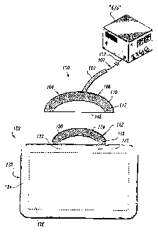
Referring now in detail to FIG. 1, a return pad cable connector is shown in
accordance with the present disclosure and is generally identified as 100.
Cable connecfior
100 includes a reusable conductive wire cable 102 which operatively couples at
a proximal
end thereof to an electrosurgical generator "E/S" and a reusable cord-to-pad
interface 104
which is disposed at a distal end thereof. Cord-to-pad interface 104 includes
an insulated
backing 106 having a conductive cord surface 108 disposed thereon which
electrically
couples to a wire 10T passing through cable 102.
An adhesive border 110 is defined about the outer periphery of the
cond~aotive c~rd surface 108. It is contemplated that cond~acfiive c~rd
surface 108 rnay he
positioned along one edge of cord-t~-pad interlace 104 to facilitate
connection with the
return pad 720. However, it is also envisioned that the conductive cord
surface 108 or
multiple conductive cord surfaces 108 may be arranged anywhere on the surface
of the
cord-to-pad interface 10~. depending upon a particular purpose or to
facilitate electrical
engagement. Preferably, the adhesive border 110 includes a non-conductive
adhesive 112
applied thereto which reduces stray electrical current from emanating from the
conductive
cord surface 108. While application of non-conductive adhesive 112 to adhesive
border
CA 02516493 2005-08-18
WO 2004/074854 PCT/US2004/004196
110 is preferred, it is envisioned that adhesive border 110 may stand alone
without adding
the non-conductive adhesive 112.
As seen in FIG. 1, cable connector 100 is configured and adapted to be
removably adhered to a return pad or return electrode 120. Return pad 120
includes an
insulated backing 122, an insulated cover 124 and a conventional electrically
conductive
member 126 retained between insulated backing 9 22 and insulated cover 124.
Insulated backing 122 includes a pad-to-cord interface 128 which e>ctends
from a side surface thereof. Pad-to-cord interface 128 includes a conductive
pad surface
130, preferably made fr~m an electrically conductive material, disposed
there~n which
electrically couples return pad 120 to the conductive cord surface 10~.
conductive pad
surface 130 is electrically connected to conductive member 126 (via at least
one
conductive wire 132 which is disposed between backing 122 and c~aver 124). An
adhesive
borrw'mr °i3~. is d~fin~d about the ov~ter peripi~e;-y of the
cond~actiN~e pad surface 130. It is
contemplated that conductive pad surface 130 is positioned to compliment the
particular
arrangements of conductive surfaces) 108 on the cord-to-pad interfaces. Much
like
adhesive border 110, adhesive border 134 may also include a non-conductive
adhesive
112 applied thereto to facilitate engagement and reduce stray electrical
currents.
Ulfpile application of non-conductive adhesive 112 to adhesive border 134 of
pad-to-cord interface 128 is preferred, the non-conductive adhesive 112 need
not be
11
CA 02516493 2005-08-18
WO 2004/074854 PCT/US2004/004196
applied to adhesive border 134 especially if the non-conductive adhesive 112
is provided
on adhesive border 110 of cord-to-pad interface 104. it is further envisioned,
that if the
non-conductive adhesive 112 is provided on return pad 120 along adhesive
border 134 of
pad-to-cord interface 128, no adhesive, either conductive or non-conductive,
need be
provided on adhesive border 110 of cord-to-pad interface 104.
A non-conductive adhesive for adhering adhesive border 110 of cord-to-pad
interface 104 to adhesive border 134 of pad-to-cord interface 1'28 is
disclosed in commonly
owned i~.S. Fatent No. 4,699,146 to aieverding, the entire contents of which
are
incorporated herein by reference. By providing cord-to-pad interFace 104 with
an adhesive
border 110 and providing pad-to-cord interface 128 with an adhesive border
134, sufficient
electrical connection is established between conductive cord surface 108 and
conductive
pad surface 130, more pacrlicc~larfy, cord-t~-pad intet~ace 904 is adhered f~
pad-to-cord
interface 128 by applying the non-conductive adhesive 112 to their respecfiive
adhesive
borders 110 and 134 end pressing the two interfaces together. In this manner,
conductive
cord s~s;face 108 directl~s contaces conductible pad surface 130 thereby
establishins~ am
electrical connection therebetween.
Turning now to FIB. 2, a return pad cable connector is shown in accordance
~rvifh another embodiment of the present disclosure and is generally
identified as cable
connector 200. Cable connector 200 includes a reusable conductive wire cable
202 having
a typical connector 204 attached to a proximal end thereof for interfacing
cable 202 with an
electrosurgicai generator (not shown) and a reusable cord-to-pad interface 206
operatively
12
CA 02516493 2005-08-18
WO 2004/074854 PCT/US2004/004196
coupled to a distal end thereof. Cord-to-pad interface 206 includes an
insulated backing
208 having a pair of conductive cord surfaces 210a, 210b disposed thereon
which
electrically couple to a wire 212 passing through cable 202.
Conductive cord surfaces 210a, 210b are preferably spaced from one
another and extend distally along a top surFace 211 of cord-to-pad interface
206. An
adhesive border 214 is defined about the periphery of each conductive cord
surface 21 Oa,
210b. Adhesive border 214 may include a non-conductive adhesive 216 applied
thereto in
order t~ facilitate mechanical connection with return pad 220. A conducfiive
adhesive 218a,
218b is applied to each conductive cord surface 210a, 210b, respectively.
As seen in FIG. 2, cable connector 200 is configured and adapted to be
removably adhered t~ return pad 22~. return pad 220 is similar to return pad
120 of FIG.
1 but includes a pair of complimentary conductive surfaces 230a, 230b which
electrically
couple with condractive pad surfaces 210x, 210b, respectively. Each
condaactive surface
wOGd, ~~0b, In t'a~rn, i3 ~'d?ll,pi~-'d i~2 ~ ~o~no~.a~~ti'a"~ ii~~ori~b~r
23~2u~, '~.~.ne~ab di~pe".o~~'d v~Iitiiin tfi~
return pad 220.
l~lore particularly, return pad 220 includes an insulated backing 222 having a
pad-to-cord interface 228 which extends from a side surface thereof. Pad-to-
cord interface
228 includes the pad conductive surfaces 230a, 230b disposed thereon which
couple with
conductive cord surfaces 210a, 210b. An adhesive border 234 surrounds the
periphery of
each conductive pad surface 230. Adhesive border 234 is configured to include
a non-
13
CA 02516493 2005-08-18
WO 2004/074854 PCT/US2004/004196
conductive adhesive 216 applied thereto which reduces stray current which may
emanate
from the conductive surfaces. A conductive adhesive 218 and covers each
conductive pad
surface 230a, 23t3b to facilitate and maintain electrical connection with
conductive cord
surfaces 210a, 210b.
Preferably, a conductive adhesive 218 is selected such that the conductivity
of the adhesive will be sufficient for the efectrosurgical power to be
conducted through the
small area of the attachment as well as provide impedance low enough for
contact quality
monitoring in the generator. While a non-conductive and a conductive adhesive
have been
contemplated for use in the present embodiment, it is envisioned that a single
conductive
adhesive can be applied to both adhesive borders 214 and 234 as well as to
both
conductive surfaces 210x, 210b and 230x, 230b. Adhesive 218x, 218b is selected
such
that the electro-conductivity of the adhesive promotes the transfer of
electric signals
between conductive surfaces 210a, 210b and 230a, 230b.
it is envisioned that a non-conductive or conductive adhesive rnay only be
~appaii~~a ~'t~ ~i~!''s~iia~ti°n~~r 3~sa°~°"fGleo~ ~ i
e~v~, ~ ~ e~ab, 2~0G~ ,.r'?, rid ~3~b ~a.~°r , ~alt'~rne~.eltiv~' 1y,
'~ non-
conductive or a conducfiive adhesive may only be applied to adhesive barders
214, 234. it
is further envisioned that adhesive does not have to be provided on conductive
surfaces
210x, 210b, 230a or 230b and an adhesive may be solely applied to one of the
adhesive
borders 21~., 234, preferably adhesive border 234 of return pad 220.
Turning now to FIGS. 3-0, a return pad cable connector is shown in
accordance with another embodiment of the present disclosure and is generally
identified
14
CA 02516493 2005-08-18
WO 2004/074854 PCT/US2004/004196
as 300. Cable connector 300 includes two major subunits; a base element 302
and a
return pad clamp 304 (see FIG. 4). As explained in greater detail below, base
element 302
and return pad clamp 304 cooperate to grip the return pa-d 400. 1t is
contemplated that
both base element 302 and return pad clamp 304 are preferably molded from a
strong,
resilient plastic material, such as acetal resin.
base element 302 includes a return pad interface 306 and a handle 308.
Preferably, handle 308 is dimensioned to facilitate gripping and may be
ergonomically
shaped to enhance "feel".
Return pad interFace 306 preferably includes a fixed jaw 312 having an L-
shaped cross-section defined by a first leg 310 for housing a series of pivot
mounts 336
disposed therein and a second leg 311 which vertically extends therefrom which
cooperates with the pad clamp 304 to secure the return pad 400 as explained in
more
detail below. A lever housing 314 is formed in the pad interface 306 and
operates to
r~l~wh~iii~~a!!y align C~i~a~.a a~~.~ro~.osiiv tli~ p~~ ~ol~~~p 30~ ~~i~l~
ii~.a~~l'6.~~" 30~a '~~~r~ p~~i~6alarly
a
locking aperture 316 extends through handle 308 and is located toward the
distal end of
the same (308). As explained in more detail below, locking aperture 316 and
lever housing
3'14 cooperate to align and secure the pad clamp 304 within handle 308.
Return pad clamp 304 includes a movable jaw 318 and a clamping fever320
which depends from movable jaw 318 and which is designed to mechanically
engage
handle 308. Clamping lever 320 includes a proximal half 322 having an offset
324 which
CA 02516493 2005-08-18
WO 2004/074854 PCT/US2004/004196
extends at an angle relative to proximal half 322. A distal half 326 depends
from offset 324
such that proximal half 322, offset 324 and distal half 326 form a generally
reverse "S"
configu ration which facilitates assembly of the cable connector 300. In other
words, the
proximal and distal halves 322 and 326 are generally parallel to one another
and offset 324
is disposed perpendicular thereto. Movable jaw 318 also includes a series of
pivot
projections 334 which are designed for mechanical engagement with pivot mounts
336 as
discussed below.
A locking pivot grip 328 is disposed on the proximal hair 322 of the return
pad
clamp 304 and a corresponding unlocking pivot grip 330 is formed on the distal
half 326.
The locking and unlocking pivot grips 328 and 330 are designed to facilitate
movement of
clamping lever 320 by an operator's finger to mechanically move/pivot jaw
member 318
from a first open position for reception of the return pad 400 to the second
locking position
which secures the return pad 400 in electromechanical engagement with fihe
cable
connector 300.
Return pad clamp 304 is pivotally mounted to base element 302 so that
movable jaw 318 lies in registration with fixed jaw 312 and pivots about an
axis "A" (see
FIGS. 5 and 6) defined through first leg 310 of the return pad interface 306.
More
particularly, the return pad clamp 304 is mounted by passing clamping lever
320 through
lever housing 314 and engaging the pivot projections 334 within the
corresponding pivot
mounts 336 clisposeci in first leg 310.
16
CA 02516493 2005-08-18
WO 2004/074854 PCT/US2004/004196
Clamping lever 320 when mounted extends along handle 308, preferably
lying in a channel 338 defined therein. IVlore particularly, clamping lever
320, when
mounted, extends through lever housing 314 and to locking aperture 316 such
that the
distal half 326 is movable within locking aperture 316 from a first locking
position wherein
movable jaw is secured tot he return pad 400 (see FIG. 5) to a second open
position for
disengaging the return pad 400 (see FIG. 6). Preferably, locking aperture 316
is designed
to accept and cooperate with clamping lever 320 in the manner described above.
For
example, in one embodiment, locking aperture 316 is generally keyhole shaped,
with a
rectangular portion designed to accommodate distal half 326 of clamping lever
320, and a
circular, chamfered thumb well 340 which surrounds un-locking grip 330. The
length of
offset 324 is preferably dimensioned to allow proximal half 322 to lie
generally flush with
the outer surface of handle 308 when clamping lever 320 is disposed in the
"locked"
position. Also, when locked, distal half 32G is generally flush with the
opposite surface of
handle 308.
,~, loc,~ing rash 342 is dis;~ose~? ~/ithin !oct~ing a per t~~re 3°( 6
and is designed to
mechanically engage a corresponding latch 332 disposed on offset 324 to secure
clamping
lever 320 in a "locked" position which, in turn, locks the cable connector 300
to the return
pad 400. As can be appreciated, cooperation between locking rail 342 and latch
332 is
made possible by dimensioning clamping lever 320 such that the distance
fromaxis A to
the tip of iatci~ 332 is slightly less than the distance from that point to
the tip of locking rail
342. Thus, when the unit is in a locked position, as shown in FIG. 5, latch
332 is securely
retained by locking rail 342. As described in more detail below, movement of
distal half
17
CA 02516493 2005-08-18
WO 2004/074854 PCT/US2004/004196
326 via un-locking grip 330 in direction "D" disengages latch 332 from locking
rail 342
which, in turn, disengages/unlocks the clamping Iever320 and releases the
return pad 400.
As best shown in FIG. 4, base element 302 also includes a conductive
surface 344 affixed to an inner facing surface of fixed jaw 312 which couples
with a
conductive wire 346 extending from handle 308 to the electrosurgical generator
(not
shown).
Returning to FIG. 3, cable connector 300 is configured and adapted to be
removably coupled to return pad 400. Return pad 400 includes an insulated
backing 402,
an insulafied cover 404 and a conventional electrically conductive member 406
retained
between instalated bathing 402 and insulated cover 404.
Insulated backing 402 includes a pad-to-cord connector408 extending from a
side surface thereof. Pad-to-cord connector 408 includes a conductive pad
surface 410
disposed the;-eon f~r el~ctricaliy c~a;~necting return pad x.00 to condu;ti~B-
e surfa~:e 344 of
connector 300. Conductive pad surface 410 is electrically connected to
conductive
member 406 via a conductive path 412. An adhesive border 414 surrounds
conductive
pad surfiace 410 and is configured such that a non-conductive adhesive 416 can
be applied
thereto. It is contemplated that a conductive adhesive can be applied between
conductive
surface 3~.4 of connector 300 and pad conductive surface 410 to assure
electrical
continuity between the same.
18
CA 02516493 2005-08-18
WO 2004/074854 PCT/US2004/004196
As seen in FIG. 5, while in a locked position connector 300 firmly holds
return
pad 400 between fixed and movable jaws 312 and 318, respectively, via the
mechanically
cooperative action of latch 332 and Pocking rail 342. In this manner,
conductive surface
344 of connector 300 and conductive pad surface 410 of return pad 400 are
vheld in
electrical contact with one another. In the open positions as shown in FIG. 6,
movable jaw
318 is rotated away from fixed jaw 312, permitting insertion and removal of
return pad 400
therefrom.
Movement between the open and the ciosed/locked positions is shown in
FIGS. 5 and 6. To move from the closed/locked position (as seen in FIG. 5),
the operator
applies a force in the direction "~" to unlocking grip 330, preferably by
pressing with a
thumb ~r finger. ~y applying a force in the direction "~" the distal half 326
and latch 332
unlocks causing the movable jaw 318 of clamping member 320 to pivot away from
fixed
jaw 312 and release pad 400. In turn, offset 324 rotates upward, forcing the
proximal half
322 out of channel 338. More particularly, applying a force in the direction
"~" rotates the
pivot ~a:ojectie~ns 33a~ ~d~~ithin pies°ot :~o!~nts 335 yo ca~~s~
movable ja~~~~ 318 to ope;~. Cnce
rotated to the "open" position, the return pad 400 is either released or a new
return pad
may be positioned therein.
~nce the return pad 400 is in place between the movable jaw 318 and the
fixed ja~re 312, the connector 300 can be locked. Locking of connector 300
involves
applying a force in a direction "C" to locking grip 328. This forces latch 332
against locking
rail 342, causing proximate leg 322 to flex and rotate latch 332 beyond
locking rail 342 thus
19
CA 02516493 2005-08-18
WO 2004/074854 PCT/US2004/004196
moving clamp lever 320 to a "locked" position (see FIG. 5). In turn, the pivot
projections of
moveable jaw 318 are rotated within pivot mounts 336 of fixed jaw 316 thereby
securing
return pad 400 between the jaw members 312, 318.
In accordance with the present disclosure, it is envisioned that each jaw
member 312, 318 may be provided with a plurality of teeth 317 formed on either
conductive
surface 344 of connector 300, the non-conductive surface of second leg 311 of
fixed jaw
312 or both. Accordingly, the plurality of teeth 317 increases the retention
of pad-to-chord
connector 408 of return pad 400 therebetween.
Turning now to FIGS. 7-10 a return pad cable connector in shown in
accordance with the principles of the present disclosure and is generally
identified as 500.
In accordance with the present disclosure it is envisioned that return pad
cable connector
500 is configured and adapted to cooperate with a return electrode 120 as
generally
described above.
l~lith parfiicular reference to FIG. 7, return pad cable connector 500
includes a
conductive refiurn wire cable 502, operatively coupled at a proximal end
thereof to an
electrosurgical generator {not shown), and a cord-to-pad interface 504
operatively coupled
to a distal end thereof. In accordance with the present disclosure, it is
envisioned that
cord-to-pad interface 50~. is made of an electrically conductive magnetic
material.
According4y, when cord-to-pad interface 504 is approximated toward or brought
into
contact with conductive pad surface 130 of return pad 120, interface 504 will
magnetically
CA 02516493 2005-08-18
WO 2004/074854 PCT/US2004/004196
couple with conductive pad surface 130. As such, the contact between cord-to-
pad
interface 504 and conductive pad surface 130 will return energy during
electrosurgical
procedures, from return pad 120 to the electrosurgical generator (not shown).
Turning now to F1G. 8, return pad cable connector 500 includes a conductive
return wire cable 502, operatively coupled at a proximal end thereof to an
electrosurgical
generator (not shown), and a cord-to-pad interface 510 operatively coupled to
a distal end
thereof. In accordance with the present embodiment, cord-to-pad interface 510
includes a
magnetic substrate 512 having at least one electrical contact 514 disposed
thereon,
wherein wire cable 502 is electrically coupled to electrical contacts) 514. It
is envisioned
that magnetic substrate 512 can be made from either conductive or non-
conductive
materials. Accordingly, when cord-to-pad interface 510 is approximated toward
or brought
into contact with conductive pad surface 130 of return pad 120, such that the
at least one
electrical contact 514 will be brought into contact with conductive pad
surface 130,
interface 510 will magnetically couple vaith conductive pad surface 130. As
such, the
~4~An~~aa.~rs b~v~~~n~~~n ~ea°~i~mi~,~a°~~0.d ii i~~.~~~5~0~ 5~
v ~insa ~do~n~i.~~oti~w°~ p~ii ~..~"~ri~ .~o~ ~ ~~ ~~°~~ll
re~~rl~i~
energy during electrosurgicai procedures, from return pad 120 to the
electrosurgical
generator (not shown).
Turning now to FIG. 9, return pad cable connector 500 includes a conductive
reiurn wire cable 502, operatively coupled at a proximal end thereof to an
electrosurgical
generator {not shown), and a cord-to-pad interface 520 operatively coupled to
a distal end
thereof. Cord-to-pad interface 520 includes a flexible substrate 522 having a
first portion
21
CA 02516493 2005-08-18
WO 2004/074854 PCT/US2004/004196
524 and a second portion 526 integrally connected to first portion 524 to
thereby define a
fold line 528. Cord-to-pad interface 520 further includes an electrically
conductive magnet
530 provided on each of first and second portions 524, 526 of substrate 522,
wherein wire
cable 502 is electrically coupled to one of the pair of magnets 530: While a
pair of
electrically conductive magnets 530 is disclosed, it is contemplated that only
magnet 530,
which is electrically coupled to wire cable 502, needs to be made from an
electrically
conductive material while the other magnet can be made from non-conductive
materials. It
is further envisioned that; if both magnets 530 are non-conductive, an
electrical contact
(not shownj can be disposed on magnet 530 which is electrical contact is
electrically
coupled to wire cable 502.
As seen in FIG. 9, wire cable 502 can extend from return pad cable connector
500 fr~m a side of substrate 522 which is parallel to fold line 528, or in the
alternative, as
shown in phantom, wire cable 502 can extend from return pad cable connector
500 from a
side of substrate 522 which is transverse to fold line 528.
lJse of return pad cable connector 500, shown in F1G. 9, requires that after
conductive pad surface 130 of return pad 120 is brought into contact with
magnet 530 wifih
is electrically coupled to wire cable 502, flexible substrate 522 is folded
along fold line 528
in order to approximate magnets 530 of first and second portions 524, 526
toward one
anoti~~:r (hereby sandwiching conductive pad surFace 130 therebetween. As
such, the
contact between magnet 530, coupled to wire cable 502, and conductive pad
surface 130
will return energy during electrosurgical procedures, from return pad 120 to
the
22
CA 02516493 2005-08-18
WO 2004/074854 PCT/US2004/004196
electrosurgical generator (not shown).
As seen in FIG. 1 D, a preferred method of coupling a magnet to a substrate
for a return pad cable connector 500 is illustrated. In particular, a magnet
540 overlies a
substrate 542 and at least one retaining device 544 (i.e., a pin) is used to
pass though
magnet 540 and imbedded in substrate 542 to secure magnet 540 to substrate
542.
Further, as seen in FIG. 10, wire cable 502 can be disposed between magnet 540
and
substrate 542. While a pin has been disclosed it is envisioned that other
methods of
coupling the magnet to a substrate can be used, such as, for example, an
adhesive,
screws, clips, clamps and the like.
The use of magnets in return pad cable connector 500 results in easier
attachment and removal of retc~rn pad cable connector 500 from conductive pad
surface
130 of return pad 120 as well as easier cleaning of the contact surfaces and a
lower profile.
lev ~~~"~rev~~~~ writF~ t~;~ pro~sant ~i~~l~~!~r'~ it i:~
~;°!/i~i~;'t°~ tl";~t r'~~mrr~ p~r~
v . a ~o.. . aaon s ro~ v .ooo~.e ~, uo aa, mn
cable connector 500 can be used in combination with a conductive adhesive
disposed
between return pad cable connector 500 and conductive pad surface 1 ~0.
While several embodiments of the disclosure have been shown in the
drawings, it is not intended that the disclosure be limited thereto, as it is
intended that the
disclosure be as broad in scope as the art will allow and that the
specification be read
likewise. Therefore, the above description should not be construed as
limiting, but merely
23
CA 02516493 2005-08-18
WO 2004/074854 PCT/US2004/004196
as exernplifications of preferred embodiments.
24