Note: Descriptions are shown in the official language in which they were submitted.
CA 02516513 2005-08-18
WO 2004/076148 PCT/EP2003/013623
OPERATING SYSTEM FOR AN EXTERNALLY OPERATED PART OF A
CLOSING UNIT
Description
The invention relates to an operating system for a part of a closing unit
which
part is to be operated externally, in particular for a mold carrier of a
closing unit,
according to the preamble of claim 1.
In the following, reference is made to a closing unit for a plastics
processing
machine with at least one mold carrier. It should be expressly noted, however,
that the present invention is equally applicable for other externally operated
parts
of closing units. The tern "externally to be operated" denotes hereby that an
opening and closing apparatus is not arranged within the closing unit but
opening
and closing of the closing unit is effected outside the closing unit.
Closing units of plastics processing machines, such as polyurethane
installations,
normally have two mold carriers which, for closing and opening of the closing
unit, are movable toward one another (closing) or away from one another
(opening). In this context, reference is made to German patent publication DE
101 52 392 which describes a closing unit for a plastics machine. The
illustrated
closing unit includes a lower mold carrier and an upper mold carrier which are
each swingable about a common axis. During operation of the entire closing
unit,
the lower mold carrier is moved back and forth between two positions, namely a
lower position in which mold elements are placed into the mold carrier or mold
parts can be removed, and an upper position in which the closing unit is
closed
altogether to process a starting material in a predetermined manner. The upper
mold carrier is also moved back and forth between two positions during
operation
of the entire closing unit, namely into an upper position in which the closing
unit
is open, and a lower position for shaping the introduced starting material.
1
CA 02516513 2005-08-18
WO 2004/076148 PCT/EP2003/013623
In DE 101 52 392, the closing units themselves are fixedly disposed at one
location, only the mold holders are swingably mounted.
It is, however, known, to arrange for example several closing units upon a
rotary
platform or turntable, with the individual closing units successively
undergoing
the same operating steps during operation of the turntable. For example, a
starting material may be introduced, when the closing unit is open. At the
same
time, the starting material can be molded to shape in another closing unit. In
still
another closing unit, a finished molded part may be withdrawn at the same
time.
The use of such devices - likewise as in DE 101 52 392 - requires operation,
especially pivoting to open and to close, of the various parts of the closing
unit in
a predefined manner.
A method known per se involves the use of external actuators, whereby a cam
roller is arranged upon an externally to-be-operated part of a closing unit,
for
example upon an upper mold carrier, for running, at least partly, on a rail
structure and is opened or closed by a gripper member at particular positions.
It
is known to implement the gripper member, for example, in the form of a U
profile, with the cam roller being able to move into the groove thereof. When
the
cam roller is received in the groove of the U profile, a movement of the upper
mold carrier is possible by movement (pivoting, travel) of the U profile. Once
the
upper mold carrier has reached a particular position, it moves out again from
the
groove of the U profile and may roll subsequently for example on a further
rail by
means of the cam roller.
The use of such rigid profiles or rails for the gripper member has, however,
the
drawback of a relative movement between cam roller and rail, when all the
closing units are operated. This leads to relatively high wear as a result of
friction. Moreover, the gripper member must be precisely adjusted and moved to
keep wear as small as possible.
2
CA 02516513 2005-08-18
WO 2004/076148 PCT/EP2003/013623
It is an object of the present invention to substantially minimize wear in an
operating system of the afore-stated type.
This object is attained by the features set forth in claim 1.
An essential feature of the invention in connection with an operating system
of a
type involved here is thus the provision of the gripper member with at least
two
freely moveable guide rollers arranged in parallel relationship at a
particular
spacing from one another and having an axis in substantial parallel or
tangential
alignment to a first direction in which the entire closing unit moves. The
spacing
between the guide rollers substantially corresponds hereby to the diameter of
the
cam roller or is selected slightly greater so that the cam roller can be
received in
this spacing. The cam roller can move into this spacing for moving the part to
be
externally operated, e.g. a mold carrier, in opening or closing directions, or
can
be moved out of the spacing following the operation.
By using freely moveable guide rollers in cooperation with the cam roller of
the
part to be operated externally, sliding friction between the cam roller and
the
gripper member can be prevented. Rather, the point of contact of the cam
roller
on the gripper member changes as a result of the rolling motion of one or both
guide rollers in axial direction of the cam roller in the absence of any
sliding
friction. There is only a rotary movement of the guide rollers.
Overall, minimal wear can be ensured even when encountering misalignments.
Of course, more than one operating unit may be provided. In this case, the
individual operating units can be tailored to continuously open the parts to
be
operated externally such as for example the mold carriers, or - with another
operating unit - to continuously close the mold carriers. Each operating unit
may
include one, two or more gripper members. When using several gripper
3
CA 02516513 2005-08-18
WO 2004/076148 PCT/EP2003/013623
members, a revolving movement of the individual gripper members prevents a to-
and-fro actuation.
According to a particularly preferred embodiment, two endless chains and
endless belts of same length are arranged in parallel spaced-apart
relationship
for attachment of the gripper members, in particular in the area of their end,
substantially transverse to the movement direction. Such an embodiment allows
the two or more gripper members to execute the opening and closing movements
of the part to be operated externally through a revolving operation of the
chains
or belts in only one direction. More information is provided with reference to
the
following exemplary embodiment.
The endless chains are preferably trained about two deflection wheels or
rollers.
One deflection roller or one toothed deflection wheel may hereby be configured
as tensioning device or in cooperation with a tensioning device. These endless
chains or endless belts are driven preferably by a motor, for example by an
electric motor.
In order to ensure the guidance of the part to be operated externally also in
the
section between two operating units, a rail may be provided in-between on
which
the cam rollers roll. The rail should hereby adjoin the gripper members in
such a
way that a smooth transition is assured between rail and gripper members when
the closing unit moves in a predefined direction.
According to a particularly preferred embodiment, several closing units are
arranged on a turntable, which rotates during operation of the closing units,
at
same radial distance to the rotation point of the turntable. They respectively
pass
successively an operating unit, a subsequent rail section as well as a further
operating unit. The first operating unit opens the externally to-be-operated
part of
the closing device from a first position to a level of the rail section, and
the
4
CA 02516513 2005-08-18
WO 2004/076148 PCT/EP2003/013623
second operating unit closes the part to be operated externally from the level
back to the first position.
An advantageous embodiment of the invention will now be described in greater
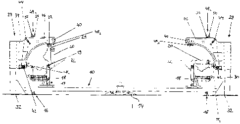
detail with reference to the attached drawings in which:
Fig. 1 shows a greatly schematic side view of a carousel-type installation
with several closing units and an operating system according to the present
invention, and
Fig. 2 shows a plan view of a carousel-type system according to Fig. 1,
with the carousel shown only partially,
The present invention will now be described in greater detail with reference
to a
carousel-type system for PUR installations (polyurethane installations).
However,
the invention is not limited to this system.
Several closing units 12 of a PUR installation, not shown in more detail, are
securely disposed on a turntable 10 at substantially same radial distance to
its
center and in angular offset relationship. Fig. 1 illustrates two closing
units in
confronting disposition, and Fig. 2 illustrates three closing units in angular
offset
disposition. Each closing unit 12 includes a lower mold carrier 18 and an
upper
mold carrier 20 which can both pivot upwardly and downwardly about a common
joint axis 19. Of course, separate joint axes may be provided for each mold
carrier.
Each closing unit 12 can be closed or opened in its entirety by pivoting the
lower
and upper mold carriers 18, 20. As a consequence, the mold carriers can be
brought into a position that allows introduction of mold elements in
ergonomically
beneficial manner or removal of molded products from the mold.
5
CA 02516513 2005-08-18
WO 2004/076148 PCT/EP2003/013623
The present invention is concerned only with pivoting of the upper mold
carrier
20. The pivot mechanism for the lower mold carrier 18 will not be described in
more detail.
The upper mold carrier 20 includes in relation to the extension of the
turntable a
radially inwardly projecting arm 21 which has an outer end for arrangement of
a
cam roller 22. The rotation axis of the cam roller 22 substantially coincides
with
the radial direction of the turntable; however it may also slightly deviate
therefrom
as a result of the off-center arrangement of the cam roller 22 on the upper
mold
carrier 20.
The operating system according to the invention includes in particular two
operating units 29 which can be seen in Fig. 1 as well as in Fig. 2. Each
operating unit 29 includes a base 32 standing on the ground for connection of
a
vertical support 30. Provided on the upper end of the vertical support 30 is a
frame of the operating unit which includes essentially two vertically aligned,
plate-
shaped side portions in mutual supporting relationship, of which one is
respectively shown clearly in Fig. 1. Arranged between both plate-shaped side
portions of an operating unit are three double toothed wheels 40, 42 and 44
having axes in parallel relationship. Each double toothed wheel 40 is arranged
on
the upper inner end of its frame 34, each double toothed wheel 42 is arranged
on
the lower end of its frame 34, and each double toothed wheel 44 is arranged
substantially vertical above a double toothed wheel 42 and horizontally
outside a
double toothed wheel 40 (compare Fig. 1 ). The frame 34 is configured between
the double toothed wheels 42 and 44 substantially in the form of a quarter
arc.
Both endless chains respectively run on the individual toothed wheels on one
side of the double toothed wheels 40, 42 and 44 and carry three gripper
members or guide elements 48~, 482, 483 staggered in circumferential direction
of
the chains and extending transversely to the movement direction of the endless
chains.
6
CA 02516513 2005-08-18
WO 2004/076148 PCT/EP2003/013623
Each guide element 48 includes a carrier, not shown in more detail, and two
freely rotatable guide rollers 50 in spaced-apart and parallel relationships.
The
distance between both guide rollers 50 is selected to correspond to the
diameter
of the cam roller 22 so that the cam roller 22 - as will be described in more
detail
hereinafter - can be received between both guide rollers. The double toothed
wheel 44 serving as tensioning element can be moved over an unillustrated
tensioning device as to allow both chains to be sufficiently tensed.
The lower deflection and guide wheel further includes a drive which is
configured
for movement of both chains in their running direction.
Arranged between both operating units 29 (not shown in more detail in Figs. 1
and 2) is a rail element in the form of a segment of a circle at approximate
level
of the innermost guide elements 483 shown in Fig. 1 to provide a connection
between both upper guide elements 483 so that a guidance of the upper mold
carrier - as will also be described hereinafter - becomes possible as the cam
roller 22 rolls on this rail between both operating units 29.
Operation of the turntable with attached closing units 12 will now be
described in
greater detail. The turntable 10 rotates in arrow direction D (Fig. 2) in
unison with
the mounted closing units 12 and is hereby supported centrally as well as on
the
outside by bearings 14 and 16. According to a preferred embodiment, 12 closing
units are arranged on the turntable 10 (only 2 closing units are respectively
shown in the Figs.). In the lower portion of the turntable, as shown in Fig.
2, the
upper mold carrier 20 assumes its closed position (corresponding to the right
side in Fig. 1 ), and is clamped with the lower mold carrier 18. In this
position, the
cam roller 22 of the upper mold carrier 20 has moved into the spacing between
both guide rollers 50 of a guide element 48, which is arranged in Fig. 1 on
the
left-hand side. After entry of the cam roller 22 into the spacing, this guide
element
48~ is moved upwards along an arcuate path, depicted in Fig. 1, through
7
CA 02516513 2005-08-18
WO 2004/076148 PCT/EP2003/013623
actuation of the drive on the lower toothed deflection or guide wheel until
reaching the position of the upper guide element 483 shown in Fig. 1. This
movement is accompanied by a relative movement between the cam roller 22
and the guide rollers 50 in two aspects. On one hand, the cam roller 22
travels
along the axis of the guide rollers, and on the other hand, the contact point
shifts
in axial direction of the cam roller 22. The latter shift does not produce,
however,
any sliding friction as a consequence of the free rotatability of the guide
rollers
and thus causes essentially no wear. Moreover, the contact lines change across
the rolling width of the various rollers which also contributes to minimizing
wear.
Movement of the cam roller 22 from the position of the lower guide element 48~
to the upper guide element 483, causes the upper mold carrier 30 to swing
upwards and thereby to open. In this position, the cam roller 22 then moves
out
of the spacing between both guide rollers 50 of the upper guide element 483,
and
travels continuously along the segment of a circle on the unillustrated guide
rail.
The upper mold carrier 20 is continuously in open state during this movement
of
the turntable 10. When the upper mold carrier 20 then reaches the further
operating unit 29, which acts as closing station, the running roller 22 moves
again into the spacing between both guide rollers 50 of the upper guide
element
483. Conversely, like the opposing operating unit 29, operation of the drive
at the
deflection and guide wheel causes the upper guide element 483, to move
downwards so that the upper mold carrier 20 is closed in analogous manner by
moving along a quarter circle path. In the lower position, the upper mold
carrier
20 is then clamped and exits the spacing between both guide rollers 50.
Through arrangement of three guide elements 48~, 482, 483 on both chains 46 of
the illustrated operating units 29, it is possible that the chains move
respectively
only in one movement direction. When suitably adjusting the chain length, one
guide element 48 then occupies an exit position whereas the other guide
element
48 s disposed in the entry position. As the upper mold carrier 20 pivots
upwards
8
CA 02516513 2005-08-18
WO 2004/076148 PCT/EP2003/013623
or downwards, a next guide element 48 is moved simultaneously into the
necessary position for the subsequent upper mold carrier 20 of a next closing
unit 12. All chains move counterclockwise in Fig. 1. Of course, embodiments
are
possible having only one gripper member which is then shuttles back and forth.
In summary, the invention allows prevention of excessive wear and to ensure
easier adjustment and compensation of manufacturing and assembly tolerances.
Wear as encountered in previously used fixed U profiles or other fixedly
arranged
rails can hereby be prevented.
9
CA 02516513 2005-08-18
WO 2004/076148 PCTlEP2003/013623
LIST OF REFERENCE CHARACTERS
round table
12 closing unit
5 14 central support with
bearing
16 outer support
17 frame of closing unit
18 lower mold carrier
19 joint
10 20 upper mold carrier
21 arm
22 cam roller
26 rail
29 operating unit
30 vertical support of the operating unit
32 base
34 frame of the operating unit
40 upper deflection and guide wheel
42 drive for lower deflection and
guide wheel
44 tensioning wheel
46 chain
48_3 guide elements
50 guide rollers