Language selection

Search

Patent 2516845 Summary

Third-party information liability

Some of the information on this Web page has been provided by external sources. The Government of Canada is not responsible for the accuracy, reliability or currency of the information supplied by external sources. Users wishing to rely upon this information should consult directly with the source of the information. Content provided by external sources is not subject to official languages, privacy and accessibility requirements.

Claims and Abstract availability

Any discrepancies in the text and image of the Claims and Abstract are due to differing posting times. Text of the Claims and Abstract are posted:

  • At the time the application is open to public inspection;
  • At the time of issue of the patent (grant).
(12) Patent Application: (11) CA 2516845
(54) English Title: OSTEOSYNTHESIS PLATE
(54) French Title: PLAQUE D'OSTEOSYNTHESE
Status: Deemed Abandoned and Beyond the Period of Reinstatement - Pending Response to Notice of Disregarded Communication
Bibliographic Data
(51) International Patent Classification (IPC):
  • A61B 17/80 (2006.01)
  • A61B 17/74 (2006.01)
  • A61B 17/76 (2006.01)
  • A61B 17/86 (2006.01)
(72) Inventors :
  • VESE, SILVANA (Italy)
(73) Owners :
  • SILVANA VESE
(71) Applicants :
  • SILVANA VESE (Italy)
(74) Agent: MARKS & CLERK
(74) Associate agent:
(45) Issued:
(86) PCT Filing Date: 2003-07-31
(87) Open to Public Inspection: 2004-09-10
Availability of licence: N/A
Dedicated to the Public: N/A
(25) Language of filing: English

Patent Cooperation Treaty (PCT): Yes
(86) PCT Filing Number: PCT/IB2003/003412
(87) International Publication Number: IB2003003412
(85) National Entry: 2005-08-23

(30) Application Priority Data:
Application No. Country/Territory Date
TO2003U000034 (Italy) 2003-02-28

Abstracts

English Abstract


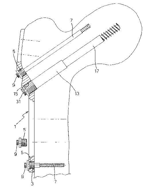
An osteosynthesis plate (1) is provided with a plurality of threaded bores (3)
in which bushings or barrels (5;13) for the passage of bone screws (7) are
screwed; said bone screws (7) being locked in position through threaded plugs
(9) that are screwed in the bushings (5) and prevent the unscrewing of said
bone screws.


French Abstract

Plaque d'ostéosynthèse (1) munie de plusieurs alésages filetés (3) dans lesquels sont vissés des cylindres ou des douilles (5 ; 13) permettant le passage de vis osseuses (7) bloquées en position par des bouchons filetés (9) vissés dans les douilles (5) de manière à s'opposer au dévissage desdites vis osseuses.

Claims

Note: Claims are shown in the official language in which they were submitted.


5
CLAIMS
1. ~An osteosynthesis plate (1) provided of a plurality of
threaded bores (3;15) in which as many bushings or barrels
(5;13) are screwed for the passage of bone screws (7;17); said
bone screws being locked in position through as many threaded
plugs (9;31) that are screwed in said bushings or barrels
(5;13) and block said bone screws (7;17) in said plate (1).
2. ~A plate as claimed in claim 1, in which said plugs (9;31)
lock in said bushings (5) the heads of said bone screws
(7; 17).
3. ~A plate as claimed in claim 1, in which said plugs (9;31)
lock in said bushings or barrels (5;13) the heads of
corresponding threaded pins or bolts (23) engaging threaded
bores (25) provided in the head of said bone screws (7;17).
4. ~A plate as claimed in claim 2, in which said bushings or
barrels (5;13) are provided with a (frusto)conical inner
surface, the cross-section area of which increases from the
plate towards the outside, towards the bone, said inner
(frusto)conical surface co-operating with a complementary
(frusto)conical outer surface of the bone screw to allow the
locking of said screw in said barrel thanks to the Cupertino
between said conical surfaces.
5. ~A plate as claimed in claim 1, in which said bushings or
barrels (5;13) comprise interrupted radially protruding rims
so as to form sectors (11) whereby said bushing can be turned

6
by using a suitable tool.
6. ~A plate as claimed in claim 1, in which the length of
said bushings or barrels (5;13) is approximately equal to the
thickness of said plate (1).
7. ~A plate as claimed in claim 1, in which said bushings or
barrels (5;13) have a length greater than the thickness of the
plate (1) and extend for part of the length of the bone screw
that is fitted in said bushings or barrels (5;13).
8. ~A plate as claimed in claim 1, in which said plate is a
femoral plate.
9. ~A plate as claimed in claim 1, in which said threaded
bores (3;15) are inclined with respect to the plane of said
plate.

Description

Note: Descriptions are shown in the official language in which they were submitted.


CA 02516845 2005-08-23
WO 2004/075766 PCT/IB2003/003412
"OSTEOSYNTHESIS P?~ATE"
The present invention refers to an osteosynthesis plate, such
as for example a femoral plate.
As it is currently known for the repair of bone fractures,
particularly femur fractures, there are used suitably-shaped
one-piece plates, provided with a plurality of holes or bores
to allow the passage of screw to be inserted into the bone.
There are known various types of plates and fastening screws
arrangements.
For example W097/08999 discloses a first type of plate
provided with bores for the passage of bone screws in which
the heads of the bone screws directly abut against the plate.
A second type of plate provided with barrels housing threaded
pins for locking - with respect to the plate - the bone screws
previously inserted into the bone is disclosed for example in
EP 0649635.
One of the problems encountered when using plates of the above
discussed type is the difficulty to firmly secure the bone
screw with the plate, once said screw has been fastened in the
bone.
A solution to the above problem has been proposed in
W001/91660 that teaches the use of internally hollow bushings
screwed in the threaded bores provided in the plate. According
to the teaching of this document, there are provided locking
bushings with a conical bore the surface of which co-operates
with the conical surface of the bone screw passing through the

CA 02516845 2005-08-23
WO 2004/075766 PCT/IB2003/003412
2
bushing. Alternatively there are provided bushings that are
rendered deformable thanks to radial cuts that block the head
of the bone screw.
The object of the present invention is to provide an
osteosynthesis plate allowing for a reliable and permanent
locking of the bone screws passing through such plate, making
its manufacturing easier and less expensive, also when the
shape of said plate is complex for fitting to several
applications.
This and other objects are accomplished through an
osteosynthesis plate as claimed in the appended claims.
A main feature of the present invention resides in that it
provides removable bushings or barrels that are threaded both
on the inner and the outer surface, and provided with closing
plugs for locking either 'the head of the bone screw or the
threaded pin engaging the bone screw.
In such a way, the osteosynthesis plate is easy to be made,
has a constant thickness for its whole length, thus achieving
a notable saving both of working time and of material.
Besides, according to the invention, the bores in the plate
can be made inclined or tilted thus allowing an inexpensive
manufacturing of particularly shaped plates.
Another advantage resides in that that although the outer
diameter of the bushings is fixed for being screwed in the
bore of the plate, their inner diameters c~ari be made different
in accordance with the size of the bone screw to be fitted

CA 02516845 2005-08-23
WO 2004/075766 PCT/IB2003/003412
3
inside it.
A not last advantage of the invention is that the bone plate
can be used with both bone screws directly screwed into the
plate, as well as with bone screws that have been screwed to
the plate in advance and are later locked through threaded
pins.
The invention will now be disclosed in detail with particular
reference to the attached drawings referring to a non limiting
embodiment thereof, in which:
Fig. 1 is a partially cross-sectioned elevation side view of
the object osteosynthesis plate
Fig. 2 is a side view of a partial longitudinal cross-section
of said osteosynthesis platen
Fig. 3 is a side view of one of said bushings to be fitted to
the plate;
Fig. 4 is a plan bottom view of the bushing of Fig. 3.
As clearly shown in the figures, a plate 1 is provided with a
plurality of threaded bores 3 in which are screwed as many
bushings 5 for the passage of bone screws 7; said bone screws
being locked in the desired position through as many threaded
plugs 9 that are screwed in the bushings 5 and lock the heads
of the screws 7 in said bushings and therefore in the plate 1.
Advantageously, the bushing 5 provides for an interrupted
radially protruding rim so as to form sectors 11 whereby the
bushing can be turned by using a suitable tool.
Preferably the length of the bushing 5 is about equal to the

CA 02516845 2005-08-23
WO 2004/075766 PCT/IB2003/003412
4
thickness of the plate l, nevertheless it could have a
different length and extend beyond the plate d along the bone
screw.
The plate 1 further includes a threaded barrel 13 that can be
screwed in a bore 15 of the plate 1. Said barrel 13 allows for
the passage of a bone screw 17.
According to the invention, the barrel 13 is provided with a
slightly (frusto)conical inner bore 19 the cross-section area
of which increases when going from the plate towards the
outside, towards the bone, and also the (non-threaded) stem of
the bone screw 17 comprises a slightly (frusto)conical portion
21 for providing a contact engagement between the two conical
parts, i.e. the inner surface 19 of the bore and the stem 21
of the screw.
A (partially) threaded pin or bolt 23 engages an axial bore 25
drilled in the head of the bone screw 17 for strengthening the
contact engagement between the conical surfaces 19 and 21 when
said screw 17 is turned to be pulled towards the plate 1 when
screwing the bolt 23. Also the hollow 29 housing the head 27
of said bolt 23 is closed by a threaded plug 31. The threaded
plug 31 allows for locking the bolt 23 and it is similar to
the threaded plugs 9 that are screwed in the bushings 5 for
locking the screw heads in the plate 1.

Representative Drawing
A single figure which represents the drawing illustrating the invention.
Administrative Status

2024-08-01:As part of the Next Generation Patents (NGP) transition, the Canadian Patents Database (CPD) now contains a more detailed Event History, which replicates the Event Log of our new back-office solution.

Please note that "Inactive:" events refers to events no longer in use in our new back-office solution.

For a clearer understanding of the status of the application/patent presented on this page, the site Disclaimer , as well as the definitions for Patent , Event History , Maintenance Fee  and Payment History  should be consulted.

Event History

Description Date
Application Not Reinstated by Deadline 2007-07-31
Time Limit for Reversal Expired 2007-07-31
Deemed Abandoned - Failure to Respond to Maintenance Fee Notice 2006-07-31
Inactive: IPC from MCD 2006-03-12
Inactive: Cover page published 2005-10-24
Inactive: Notice - National entry - No RFE 2005-10-20
Inactive: Inventor deleted 2005-10-20
Application Received - PCT 2005-10-06
National Entry Requirements Determined Compliant 2005-08-23
Application Published (Open to Public Inspection) 2004-09-10

Abandonment History

Abandonment Date Reason Reinstatement Date
2006-07-31

Maintenance Fee

The last payment was received on 2005-08-23

Note : If the full payment has not been received on or before the date indicated, a further fee may be required which may be one of the following

  • the reinstatement fee;
  • the late payment fee; or
  • additional fee to reverse deemed expiry.

Patent fees are adjusted on the 1st of January every year. The amounts above are the current amounts if received by December 31 of the current year.
Please refer to the CIPO Patent Fees web page to see all current fee amounts.

Fee History

Fee Type Anniversary Year Due Date Paid Date
Basic national fee - standard 2005-08-23
MF (application, 2nd anniv.) - standard 02 2005-08-01 2005-08-23
Owners on Record

Note: Records showing the ownership history in alphabetical order.

Current Owners on Record
SILVANA VESE
Past Owners on Record
None
Past Owners that do not appear in the "Owners on Record" listing will appear in other documentation within the application.
Documents

To view selected files, please enter reCAPTCHA code :


To view images, click a link in the Document Description column. To download the documents, select one or more checkboxes in the first column and then click the "Download Selected in PDF format (Zip Archive)" or the "Download Selected as Single PDF" button.

List of published and non-published patent-specific documents on the CPD .

If you have any difficulty accessing content, you can call the Client Service Centre at 1-866-997-1936 or send them an e-mail at CIPO Client Service Centre.


Document
Description 
Date
(yyyy-mm-dd) 
Number of pages   Size of Image (KB) 
Representative drawing 2005-08-22 1 16
Drawings 2005-08-22 3 49
Description 2005-08-22 4 151
Abstract 2005-08-22 1 51
Claims 2005-08-22 2 55
Notice of National Entry 2005-10-19 1 192
Courtesy - Abandonment Letter (Maintenance Fee) 2006-09-24 1 175
PCT 2005-08-22 3 109