Note: Descriptions are shown in the official language in which they were submitted.
CA 02517171 2005-09-20
WO 2004/082540 PCT/GB2003/002503
CONTRACEPTIVE SHEATH WITH INTEGRATED BEAD CONSTRUCTION
FIELD OF INVENTION
This invention relates to a tubular protective device or sheath for protection
against
the transfer of infectious matter during sexual intercourse. More
particularly, the invention
relates to a thin walled tubular protective device having a closed end and an
open end
wherein the device has a integral bead at its open end.
BACKGROUND OF THE INVENTION
Condoms are devices that are used for both contraception and protection during
sexual intercourse against the transfer of infectious matter such as bacterial
and viral
microbes that cause venereal diseases. The continued increase in the
incidences of
HIV/AIDS has caused various health organizations to encourage people to
increase the
use of condoms during sexual intercourse in or to prevent the further spread
of the
disease.
Condoms comprise a thin tubular casing that is typically manufactured from
natural rubber latex and that has an open end and a closed end. Traditional
condoms are
drawn over the penis before coitus. The casing of the condom has an inner
diameter that
is selected so that the condom fits tightly on the penis. At the open end of a
condom an
elas'tic, flexible ring or rolled portion of latex is usually provided. This
ring portion is
generally the same diaineter as the tubular casing of the condom. This elastic
ring portion
serves primarily to secure the condom on the penis and to prevent leakage of
semen for
the interior of the condom. These elastic ring portions of a condom do not
radially extend
the open end of the condom. Indeed, the rings do not supply enougll rigidity
to alter the
shape of the condom.
1
CA 02517171 2005-09-20
WO 2004/082540 PCT/GB2003/002503
It is generally accepted that HIV/AIDS can only be transferred through contact
with the carrier's bodily fliud. During sexual intercourse such a transfer of
HIV/AIDS
occurs when skin lesions of the carrier contact the inucous membrane or skin
of the
carrier's partner or through transfer of the carriers semen. Such a transfer
of HIV/AIDS
may occur at the base of the penis and at the vulva. There is a risk that
lesions in these
areas can be caused to bleed during sexual intercourse. When using a standard
condom,
these areas are unprotected or unshielded by the condom, and consequently a
condom
does not offer full protection against the transfer of infectious matter such
as HIV/AIDS.
Numerous attempts have been made to design a cond m or condom-like device
that provides effective contraception and/or more protection against the
transfer of
infectious matter than the standard condom. A sampling of these attempts are
described
below.
An article, "Outline For Successful Prophylactic Program" (Waterbury, Conn.:
The Hemingway Press, 1934), the Gee Bee Company, 7-16, discloses a
prophylactic
device entitled, "The Gee Bee." This device is a loose fitting tubular
prophylactic having
a grooved outer ring. The grooved outer ring does not form a collar-shaped,
outwardly
extending portion at the open of the prophylactic. This invention does not
disclose any
description of a "female" embodiment having a means for retaining the closed
end of the
device in the vagina.
German Patent Number 210,413 to Hollmann discloses a condom-like device
having an outer ring. The outer ring of this invention radially extends the
opening of the
condom. This invention has no means for retaining the closed end of the device
in the
vagina.
U.S. Pat. No. 899,251 to Graham discloses an animal breeder's bag. The bag is
a
condom-like device for livestock that can be used to collect semen. The bag
contains a
2
CA 02517171 2005-09-20
WO 2004/082540 PCT/GB2003/002503
fixed inner band that is positioned at about the middle of the device. This
position for the
attachinent of the band provides for a tube and a bag-like extension. The
purpose of the
band and cross strips is to collect semen in a pocket. A rubber frame can be
made in
various shapes, but is not disclosed as forming a collar-shaped, outwardly
extending
portion at the opening off the prophylactic. The band of this device is
designed and
positioned on the device in order to provide a semen collection bag. The band
does not
have a structure that is located at the closed end of the device to provide a
retaining
means such as is required for a "female condom".
U.S. Pat. No. 4,004,591 to Freimarlc discloses a birth control device. This
birth
control device is a female condom made of a strong rubber, plastic, or other
similar
material. This condom has a rigid, ring-like rim that is bent or scalloped.
This rim can be
a wire. The rim is not adapted to radially extend the open end of this device
because this
device is a hard molded material and not flexible. The cross-sectional
dimensions of this
condom are disclosed as being sufficiently large to easily accommodate the
average width
of the penis with some additional clearance space. The primary function of
this device is
to prevent unwanted pregnancy. This device is useful in preventing the spread
of
venereal disease. This device provides no means at the vulva to prevent an
exchange
between partners of secreted fluids that can contain infectious agents.
Additionally, this
birth control device is intended for use by females, but includes no means to
secure or
maintain the device in the vagina.
U.S. Pat. No. 4,630,602 to Strickman et al. discloses a disposable
contraceptive
cervical barrier. The cervical barrier of this invention is similar to
standard diaphragms in
size and design. This cervical barrier contains various "cavities for cells"
that can hold
spermicidal lubricants. These spermicidal lubricants can als6 be placed in
numerous
grooves within the body of the cervical barrier. Urethane polyiners are used
to make the
3
CA 02517171 2005-09-20
WO 2004/082540 PCT/GB2003/002503
device. The cervical barrier of this invention, unlike a condom, has no
tubular side walls
to prevent the exchange of secretion between partners that can contain a
venereal disease.
Retained sheaths or "female condoms" have been sold for some time. One type of
such a device is disclosed in the Hessel et al. patents, U.S. Patents
4,735,621, 4,976,273,
5,094,250, 5,490,519, and 5,623 946. In the principle embodiment discussed in
these
patents, the urethane ring at the open end of the tubular member is a separate
unit from
the urethane sheatli itself. The sheath is then attached to the ring through
for example a
welding step. The Hessel patents also discuss that the ring can be formed by
rolling the
polymer material that forms the walls of the tubular structure from the open
end, so as to
form a ring of material. This ring of material can then be kept from unrolling
by heating
or using an adhesive.
The Hessel patents while they mention use of natural rubber latex, never
address
the problems associated with such a construction. Specifically, while rolling
a ring is
theoretically possible it presents many challenges. Typical polymer materials
used in the
construction of contraceptive barriers (i.e., natural rubber latex or
polyurethane) will rip
upon rolling or are too sticking to be effectively rolled. Often when a
material is rolled
into a bead of sufficient size, air or moisture is captured in the bead and
upon drying the
air expands and moisture boils resulting in a rupture in the bead.
4
. .._ .. . . ..._._. .._ _..... __ ... . ... .... . .. I .. _. . ...
..,...,._. ._..
CA 02517171 2008-08-19
76909-302
SUMMARY OF THE INVENTION
The present invention is directed to a contraceptive barrier with an integral
bead
and methods for it-s manufacture. By "integral bead" it is meant that the bead
or ring at
the open end of the device is constructed from the same sheet that makes up
the barrier
wall without any additional pieces. In some embodiments, the device of the
present invention is a
contraceptive device that is inserted within the vagina and retained there
during coitus. The device
includes a barrier wall that forms a pouch. The pouch is generally tubular
shaped with an
open end and a closed end. The open end has a diameter greater than the pouch
creating a
io trumpet shape or a flange at the open end. The diameter of the pouch is of
a sufficient
size to allow free movement of a penis during coitus. Around the outer edge of
the open
end is a bead that provides rigidity to the open end. The bead is an integral
bead. The
bead is formed by rolling the barrier wall of the pouch upon itself, until a
bead of
sufficient thickness to provide the needed rigidity is obtained. An adhesive
material may
be used to maintain the bead in the rolled position and keep it from
unrolling.
The device may also include a retaining member for keeping the device within
the
vagina dttring coitus. This retaining member is generally located at the
closed end of the
tubular pouch. It could take on many forms including a retaining ring or
sponge.
In the present invention the pouch is manufactured using a dipping process.
Specifically, the present invention is preferably coniposed of a synthetic
nitrile latex
material. A former, of the appropriate shape, is dipped into a suspension of
the synthetic
nitrile latex to form a sheath. The sheath is then cured to allow cross
linking to occur in
the synthetic nitrile latex and make it sufficiently durable. Synthetic
nitrile latex has the
advantage of being relatively inexpensive, easy to work with and not subject
to the
allergic reactions often found with natural rubber latex. In addition,
synthetic nitrile latex
is significantly stronger than natural rubber latex and provides a better
barrier against the
5
CA 02517171 2008-08-19
76909-302
transmission of disease. In addition, synthetic nitrile
latex has a higher modulus of elasticity than prior used
natural rubber latex in condoms. This means the product
will form a loose fitting liner in the vagina that will stay
in place during intercourse. A natural rubber latex device,
being more elastic and lower modulus material, is more
likely to be dislodged.
In accordance with an aspect of the present
invention, there is provided a method for manufacturing a
female condom comprising: dipping a former into container of
synthetic nitrile latex such that the synthetic nitrile
latex forms a coating on the former, said coating defining a
tubular wall with an open end and a closed end; drying the
coating on the former; partially curing the coating on the
former; after the partial curing, rolling the open end of
the tubular wall upon itself to form an integral bead
wherein the integral bead is of a diameter greater than that
of the tubular wall; and finally curing the coating after
the integral bead is formed.
In accordance with another aspect of the present
invention, there is provided a female condom comprising: a
tubular wall comprised of synthetic nitrile latex, said
tubular wall being open at one end; an integral bead located
at the open end, wherein the open end is of a diameter
greater than the diameter of the tubular wall and said
integral bead is at least about 3 mm in cross section
diameter and said integral bead is kept from unrolling as a
result of cross-linking bonds formed in a curing process;
and a retaining mechanism located within the tubular wall.
In accordance with still another aspect of the
present invention, there is provided a female condom
comprising: a tubular wall comprised of synthetic nitrile
6
, . _ ... .. i . . ,....._. ..
CA 02517171 2008-08-19
76909-302
latex, said tubular wall being open at one end being about
55 millimeters to about 85 millimeters long and have a wall
thickness between about 50 microns and 70 microns; an
integral bead located at the open end, wherein the open end
has a diameter at least about 40% greater than the diameter
of the tubular wall, said integral bead is at least about
3 mm in cross section diameter, and said integral bead is
kept from unrolling by an adhesive that is comprised of the
same synthetic nitrile latex as the tubular wall; and a
retaining mechanism located within the tubular wall.
DESCRIPTION OF THE DRAWINGS
Figure 1 is an exemplary embodiment of the present
invention.
Figure 2 is a flow chart illustrating a portion of
the process used to manufacture the structure of the present
invention.
Figure 3 is another exemplary embodiment of the
present invention with a modified retention ring.
Figure 4 is yet another exemplary embodiment of
the present invention with a further modified retention
ring.
Figure 5 is still another exemplary embodiment of
the present invention with a modified retention ring.
Figure 6 is again another exemplary embodiment of
the present invention with a modified retention member at
the closed end of the sheath.
Figure 7 is another exemplary embodiment of the
present invention with a further modified retention member
at the closed end of the sheath.
7
CA 02517171 2008-08-19
76909-302
DETAILED DESCRIPTION OF EMBODIMENTS
The invention relates to an iniproved tubular protective device, such as a
female
condom like device or vaginal shield, and an improved metliod for
manufacturing it.
Exemplary embodiments of various structures of the present invention are shown
in
Figures 1 and 3-7. These devices have been shown to provide protection against
the
transfer of infectious matter, including HIV/AIDS and venereal diseases. The
protection
is enhanced because the tubular protection device has at its open end an
outwardly
extending collar that is supported by a rigid bead or ring like structure. The
bead is
desirably adapted to maintain the collar of the device in a radially extended
or stretched
condition. As a result, the bead has to be of sufficient size and rigidity to
extend the
collar. The collar is preferably of a dimension that covers the vulva
completely and is
relatively immovable during coitus. The tubular protective device preferably
has a
sufficiently large inner diameter to allow movement of a penis with respect to
the walls of
the tubular device. The walls of the tubular device are held in a relatively
immoveable
state or condition within and against the vaginal wall by a retaining
mechanism. In one
exemplary embodiment, the retaining niechanism is a ring like member that is
either
removable or integrally connected to the closed end of the tubular protective
device.
The flexible, thin wall tube of the invention is desirably cylindrical in
shape
having an open end and a closed end. The tube is preferably made of a
synthetic polynier
materiaI. Particularly preferred are synthetic latex materials and in
particular synthetic
nitrile latex.
The wall tluck-ness of the tubular protective device can vary. Typically,
thinner
wall thicknesses for the device allow more sensitivity during coitus. However,
the wall
thickness must be sufficient to provide the necessary strength and prevent
rupture.
Moreover, it is preferred that the wall thickness be uniform throughout the
device, some
8
CA 02517171 2005-09-20
WO 2004/082540 PCT/GB2003/002503
variation in the wall tliickness is however acceptable. Preferably, the wall
thickness for
the device, is between 50 and 70 microns.
The internal or inner diameter of the tubular protective device in its
unstretched
state is desirably of a sufficiently large dimension to permit movement of a
penis with
respect to the protective device during sexual intercourse. A tubular
protective device
having a large inner diameter functions as a liner for the vaginal wall or as
a "vaginal
pouch". In this situation, the device is relatively stationary to the vaginal
wall and the
glans is in direct contact with the surface against which it is moving. This
structural
arrangement, wherein the inner diameter of the tubular protective device is
larger than a
penis, provides greater sensitivity for both partners.
Standards within the industry for condoms, typically, do not define the imier
diameter of a condom, but define the acceptable width of the condom when it is
laid flat
on a surface. A condom having a width of about 47 millimeters to about 51
millimeter is
considered, within the industry, to be foim fitting. Contoured or loose
fitting condoms
have a width of about 50 millimeters to about 54 millimeters. For this
invention an
acceptable width is at least about 50 millimeters in an unstretched state
along the entire
length of the tube. A desirable range for the width of the tubular protective
device of this
invention is between about 55 millimeters and about 85 millimeters.
The collar-shaped, outwardly extending portion of the tubular protective
device
has a mechanism for radially stretching or extending the collar, such as a
bead or ring-like
member. Furthermore, the bead serves to prevent the open end of the tubular
protective
device from being pushed into the vagina during sexual intercourse. As
mentioned
above, this mechanism for extending the collar or ring-like member, in the
most desirable
embodiments of the invention, is integral to the open end of the tubular
protective device
and is formed from the walls of the device. Such a structure is formed by
rolling the walls
9
CA 02517171 2005-09-20
WO 2004/082540 PCT/GB2003/002503
of the device, from the open end of the tube so as to form a ring of material.
Steps should
be taken to maintain the structure of this ring and prevent it from unrolling.
The diameter of the ring formed by the integral bead is desirably large enough
to
prevent the exchange of secretions between partners during sexual intercourse.
In other
words, the diameter of the ring formed by the integral bead is desirably large
enough such
that the vulva and the base of the penis are covered by the extended collar.
The preferred
einbodiments of the invention have a first diameter for the tube of the device
and a second
diameter for the ring formed by the integral bead, wherein the second diameter
is larger
than the first diameter. Acceptable diameters for the ring formed by the
integral bead of
the device are at least about 50 millimeters and desirably between about 60
and about 75
millimeters. Preferably, the collar is conically shaped and when a tubular
protective
device having an inner diameter of approximately 50 millimeters is used, the
collar,
supported by the integral bead, preferably, has an inner diameter of
approximately 70
millimeters.
The integral bead must be of sufficient size and rigidity to support the
collar. As a
result, the integral bead of the present invention must be significantly
larger than the ring
formed on a standard condom. In prior art device, a wire or plastic ring was
used to
provide this rigidity. The present invention eliminates the need for such a
substructure.
An embodiment of the manufacturing process for forming the product of the
present invention is set forth in Figure 2. In this exemplary process, the
tubular device is
manufactured by first dipping a preheated (70 C) former (preferably ceramic)
into a
coagulant, such as calcium nitrate (CaNO3). Then the former, coated witli the
coagulant,
is dried. The dried former is then dipped into a heated aqueous suspension of
synthetic
latex polymer material. The coagulant allows the synthetic latex to better
form on the
fonner. The synthetic latex is then dried in an oven until substantially dry.
In an
CA 02517171 2005-09-20
WO 2004/082540 PCT/GB2003/002503
exemplary embodiment, the material is then leached in water. After the
leaching process=
it is allowed to air dry. The synthetic latex is then cured. After the
syntlletic latex is
cured, the open end of the tubular device is rolled upon itself to form the
integral bead.
The bead is rolled to a substantial size in order to provide the rigidity. The
integral bead
is at least about 3-3.5 millimeter in cross section diameter. In general, this
entails rolling
about 130 to 190 millimeters of the tubular device upon itself. In one
exemplary
einbodiment, at the last roll of the bead an adhesive is applied to the outer
wall of the
tubular device and rolled up into the bead. This adhesive keeps bead from
unrolling.
While any appropriate adhesive material could be used, in a particular
embodiment the
adhesive is the same synthetic latex that is used to form the tubular device.
If the
synthetic latex is used as the adliesive, it is advantageous to then further
cure the device
for a second time.
In another exemplary embodiment the use of an adhesive may be avoided. In this
embodiment the first cure of the synthetic latex is done at a temperature and
for a time
that allows only a partial cure , such that synthetic polymer retains the
ability to bond
with itself. The bead is then formed by rolling the open end of the tubular
device upon
itself. The device is then cured for a second time, completing the curing
process,
resulting in cross-linlcing within the bead and preventing it from unrolling.
Insertion into the vagina of the tubular protective device of the invention
can be
done by either the man or the woman. The device can be inserted in the
traditional
inanner wherein the male partner places the device over the penis before
coitus. The
female partner can insert the device by hand or by means of an insertion probe
or
applicator.
The tubular protective device has structure that prevents the unintentional
removal
or from slipping out of the device fioin the vagina once insertion into the
female partner
11
CA 02517171 2005-09-20
WO 2004/082540 PCT/GB2003/002503
has occurred. Prevention of unintentional removal is accomplished by a
mechanism for
retaining the device in the vagina. The mechanism for retaining can be
fashioned in a
variety of structures, but is desirably a circular elastic member such as an
elastic ring.
This member or ring can be placed internal or external to the wall at or
essentially at the
closed end of the tubular protective device. After being placed correctly in
the vicinity of
the uterus, the circular elastic member or elastic ring is maintained within
the vagina in
the same maimer as a diaphragm.
The mechanism for retaining the tubular device in a vagina can comprise one of
many structures that are fixed or removable. Ring-like members can provide
suitable
mechanisms for retaining as discussed above. Ring-like members are made more
suitable
for use as retaining mechanisms when at least one segment of the ring is
removed. Such
embodiments, having a ring with an open segment, permit the ring-like member
to be
pinched or partially collapsed for easy insertion into the vagina. An open or
collapsible
retaining mechanism can be desirable in embodiments wlierein the mechanisms
for
retaining is other than a ring-like member. Such embodiments can be in the
forin of ribs
that are longitudinally molded into or extrd.ided onto the closed end of the
device as well
as cap-like retaining mechanisms. Circular sponges located at the closed can
also be
effective retaining mechanism. Regardless of the structure adopted for the
retaining
mechanism, the retaining mechanisms must be structured such that it does not
weaken the
wall of the tubular protective device nor interfere with coitus,
In one exemplary embodiment, the retaining mechanism is a ring made of an
elastic material that softens when heated to body temperature such as a
polyurethane
material. The ring is placed, unattached, at the closed end of the tubular
device. The ring
is of a size to hold the wall of the tubular device against the wall of the
vaginal cavity.
12
CA 02517171 2005-09-20
WO 2004/082540 PCT/GB2003/002503
The intenial diameter of the ring is of sufficient size so as not to interfere
with coitus.
The fact that the ring softens at body temperature facilitates the removal of
the device.
Insertion of the tubular protective device into the vagina can be facilitated
by
enclosing the closed end of the device in a sheathing which is axially movable
relative to
the tubular protective device. During the insertion of the tubular protective
device into the
vagina, the sheathing is moved backwards and, thus, opens for insertion of the
closed end
of the tubular protective device. Such a sheathing is not typically present if
a means for
retaining the device in the vagina, such as an elastic ring, is present.
A lubricant is, desirably, applied to the tubular protective device prior to
or in
connection with the insertion of the tubular protective device. The lubricant
is applied at
least to the inner side of the device in order to reduce friction during
contact with the
penis. If desired, a h.ibricant can also be applied to the exterior side of
the device.
Application of a lubricant to the exterior side of the tubular protective
device can
facilitate the insertion of the device into the vagina.
Selection of a desirable lubricant can vary greatly. The selection of a
lubricant
depends, in part, upon the compatibility of the lubricant with the polymer
synthetic latex
used to manufacture the device. Desirable lubricants can include ointments,
creams, or
water-based mucilages or mucilage-like substances such as cellulose-based
lubricants.
The invention is described in more detail with reference to the figures that
show
desirable einbodiments of the tubular protective devices according to the
invention.
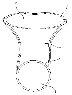
FIG. 1 is a tubular protective device according to the preferred embodiment of
this
invention. The tubular protective device 1 has an open end 2. The open end 2
has an
integral bead 3. A closed end 4 of the tubular protective device has an
retaining ring 5. In
this embodiment the retaining ring 5 is placed unattached in the closed end 4
in a plane
13
CA 02517171 2005-09-20
WO 2004/082540 PCT/GB2003/002503
transverse to the integral bead 3. The integral bead 3 is constructed entirely
from rolling
of tubular wall upon itself.
FIG. 3 is an alternative embodiment of a tubular protective device 10
according to
this invention. A ring-like member 11 is a fixed to the closed end of the
tubular protective
device 10. The ring-like member 11 has an open segment 12 for collapsing the
ring-like
member in order to facilitate insertion of the closed end of the tubular
protective device.
FIG. 4 is an alternative embodiment of a tubular protective device 15
according to
this invention. This embodiment has two "opposing" crescent-shaped, ring-like
members
16A and 16B. Ring-like members 16A and 16B can be compressed, but provide
uniform
radial extension of the closed end of the tubular protective device 15. The
uniform radial
extension is desirable in order to ensure that the closed end is properly
seated in the
vagina in the same manner that a diapliragm is wom. Additionally, the ring-
like members
16A and 16B provide a "ribbed effect" for the tubular protective device 15. It
is iinportant
to know that the terminal portion of the present ring-like members 16A and 16B
are softly
roundly so as to prevent uneven stress on the wall of the tubular protective
device 15 or
interference with coitus.
FIG. 5 is an altemative embodiment of a tubular protective device 20 according
to
this invention. The closed end of this embodiment of the invention has
longitudinal
segments 21 positioned at the closed end to provide a means for retaining the
tubular
protective device 20. Desirably, these longitudinal segments 21 are molded or
extruded to
have a slight curvature along the longitudinal axis of the tubular protective
device 20.
This curvature enables the longitudinal seginents 21 to radially extend the
closed end of
the tubular protective device 20. The spaces 22 in between the longitudinal
segments 21
enable the closed end to be compressed for insertion into a vagina.
14
CA 02517171 2005-09-20
WO 2004/082540 PCT/GB2003/002503
FIG. 6 is an alternative embodiment of a tubular protective device 25
according to
this invention. The closed end of this device has a star-shaped retaining
means 26. The
star-shaped retaining means 26 has a plurality of longitudinal extensions 27
which
radially exteiid the closed end of the tubular protective device 25.
FIG. 7 is an alternative embodiment of a tubular protective device 30
according to
this invention. This embodiment has a cap-like portion 31 at the closed end of
the tubular
protective device 25. Cap-like portion 31 has an open segment 32 which can be
compressed together for easy insertion of the closed end of the tubular
protective device
30. The cap-lilce portion 31 provides an effective retaining means, but its
thickness can
interfere with coitus during use of the tubular protective device 30. The cap-
like portion
31 can, optionally, have a plurality of open portions 32.
Manufacture of the tubular protective device, consistent with the process set
fortla
in Figure 2, is ftirther described by the following example:
Example 1
Initially a synthetic latex coinpound is compounded in a conventional manner.
The compounding step consists of mixing latex concentrate with stabilizer and
a chemical
dispersion agent in order to create a homogeneous substance appropriate for
manufacturing the invention. A ceramic fonner in the desired shape is cleaned
and pre-
heated at 70 C for at least thirty minutes. The pre-heated former is dipped in
to a
coagulant (such as CaNO3) with about zero dwell time such that the surface of
the former
is coated with the coagulant. Care should be taken to ensure that the layer of
coagulant is
unifonn over the surface of the former. The coagulant coated former is then
dried in an
oven for about one to two minutes at 120 C to 130 C. Once dry, the former is
dipped in a
suspension of synthetic latex (zero dwell time) at 26 C - 30 C. The synthetic
latex coated
fornner is then removed and dried in an oven at 90 C for about three minutes.
This drying
CA 02517171 2005-09-20
WO 2004/082540 PCT/GB2003/002503
process may result in a partial cure of the synthetic latex on the former. The
latex coated
former is t11en leached in water two to three minutes at a temperature of 65
C. This
leaching removes residual soluble material from the product. The leaching
solution may
include a biocide suspension in the water to further eliminate any potential
germs. After
leaching the synthetic latex coated former is allowed to dry at ambient
temperature.
The integral bead is then formed by rolling the open end of the synthetic
latex
upon itself wliile on the former. The former may be adopted with an annular
groove to
receive the bead when formed. A strip of wet synthetic latex may be applied to
outside of
sheath at the bottom of the integral bead. The integral bead is then rolled to
encompass
the wet synthetic latex. The device is subjected to a second cure for about 15
minutes at
95 C to 120 C. This second cure creates cross linking bonds in the synthetic
latex and
both secures the bead an toughens the material.
After the second cure the device is removed from the former. A polyurethane
ring
may be place is the closed end of the device. The product is then leak tested,
lubricated
and readied for packaging.
Conclusion
The present invention represents an improvement in both the structure and the
methods for manufacturing female condoms. The present invention provide a
device that
less expensive to manufacture while maintaining a high quality product. The
invention
overcomes the issues experience in the prior art that resulted in inefficient
and ineffective
manufacture of female condoms.
16