Note: Descriptions are shown in the official language in which they were submitted.
CA 02517719 2005-08-29
WO 2004/081884 PCT/US2004/007211
1
CASH DISPENSING AUTOMATED BANKING MACHINE
AND METHOD
TECHNICAL FIELD
This invention relates to automated transaction machines. Specifically
this invention relates to an automated transaction machine including a note
delivery mechanism for delivering sheets one sheet at a time from a stack.
BACKGROUND ART
Automated transaction machines include automated banking machines.
A conunon type of automated banking machine is an automated teller machine
("ATM"). ATMs may be used to perform transactions such as dispensing
cash, accepting deposits, making account balance inquiries, paying bills and
transferring funds between accounts. ATMs and other types of automated
banking machines may be used to dispense documents such as tickets, scrip,
vouchers, checks, gaming materials, receipts or other documents. While many
types of automated banking machines, including ATMs, are operated by
consumers, otlier types of automated banking machines may be operated by
service providers. Such automated banking machines may be used by service
providers to provide cash or other types of sheets or documents when
performing transactions for customers. For purposes of this disclosure, an
automated banking machine shall be construed as any machine that is capable
of carrying out transactions wliich include transfers of value.
A popular brand of automated banking machine is manufactured by
Diebold, Incorporated, the assignee of the present invention. Such automated
banking macliines are capable of selectively dispensing sheets to users of the
machine. A sheet dispensing mechanism used in such macliines includes a
picking mechanism which delivers or "picks" sheets generally one at a time
from a stack of sheets stored within the machine. The sheets are transported
through one or more transports within the machine and eventually delivered to
a user. A picking mechanism used in some Diebold automated banking
CA 02517719 2008-08-12
WO 2004ro81884 PCT/US2004/007211
2
machines is described in U.S. Patent No. 5,577,720.
The picking mechanism includes a rotating
picking menlbpr that comprises a plurality of cylindrical portions disposed
along a shaft. Each cylindrical portion includes a high friction segment along
a portion of the circumference. These high friction segments are sized and
positioned such that upon each rotation of the picking member, an end note
bounding an end of the stack is exposed to the moving high friction segment.
Such exposure causes the end note to be moved away from the stack in
engageinent with the moving cylindrical portions of the picking member.
io Disposed adjacent to each of the cylindrical portions of the picking
member and in the direction of rotation of the picking member relative to the
stack when picking the notes, is at least one stripping member. A stripping
member is disposed in generally abutting relation with each of the cylindrical
portions of the picking member. Each stripping member is generally circular
and generally does not rotate during rotation of the picking member in a note
picking direction. The stripping member generally operates to prevent all but
the end note from moving out of the stack upon rotation of the picking
member. The stripping member operates to prevent generally al1 but the end
note feom being delivered from the stack because the force applied by the
picking member directly on the end note exceeds the resistance force applied
by the stripping inember to the end note. However the resistance force of the
stripping member acting on notes in the stack other than the end note, because
such notes are not directly engaged with the picking member, generally
prevents the other notes from nioving froni the stack.
In the exemplary embodiment of the picking mechanism, the st_ripping
members are eacli supported through one-way clutch meclianisms. These one-
way clutch mecha.nisms prevent the stripping members from turning
responsive to the force appliRd to the stripping menibers as the picking
member moves to pick a note. However the one-way clutcli in connection
3 C with each stripping member enables each stripping member to rotate in a
CA 02517719 2008-08-12
WO 2004/081884 PCT/I:S2004/007211
J
3
direction opposite to that which the stripping member is urged to niove during
picking. This is useful in situatioics where a doubles detector senses that
more
than tme note has moved past the stripping inember.. In such circtunstan.ces
a.
controller operating in the banking machine may operate to cause the pieking
meniber to rotate in an opposed direction, which is the opposite of the
direction in which the picking member normally moves when picking a note.
As the picking member moves in this opposed direction, the stripping member
rotates so as to facilitate the movement of the multiple sheets back toward
the
stack. Once the multiple sheets have been moved back toward the stack and
1 o beyond the stripping member, the controller may operate to cause the
picking
mechanism to again try to pick a single note from the stack.
In many existing automated banking machines produced by the
assignee of the present invention, notes that are picked from the dispenser
are
moved through a transport of the type shown in U.S. Patent No. 5,342,165.
Such transports
include a plurality of generally parallel and transversely disposed belt
flights
which move the notes in engagement therewith. Disposed between each
adjacent pair of belt flights is a projecting member. The projecting member
generally extends to at least the level of the sheet engaging surfaces of the
adjacent belt flight. As a result sheets are captured in sandwiched relation
between the projecting members and the belt flight. This sandwiching of the
sheets causes the sheets to move with the moving belt flights to selected
location.s in the machine. For example as shown in the incorporated
disclosure, the slieets are moved in engagement with the belt flight into a
2= stack. Once the stack of shee-s has been accumulated, the stack is engaged
with belt tlijhts so that it can be moved to be presented to a user of the
machine.
The sheet dispenser mechanisms and transports described are highly
reliable and havF been used extensively in automated banl:sng machines.
However, problems can sometimes be encountered in the picking and transport
CA 02517719 2005-08-29
WO 2004/081884 PCT/US2004/007211
4
of sheets. In some circumstances sheets may have relatively high surface
tension and an affinity for adjacent sheets. This may prevent an end note from
being readily separated from a stack of sheets. Alternatively an end note may
be woaxi or soiled in a way that reduces its frictional properties. In such
cases
an end note may be more resistant to the forces of the higlx friction segment
on
the picking member and will not readily separate from the stack. In
alternative
situations the picking mechanism may be picking a type of sheet which is
plasticized or otherwise has reduced frictional properties relative to the
high
friction segment on the picking member. In such circumstances picking the
end note from a stack may prove more difficult to accomplish reliably.
Difficulties in picking sheets may also be encountered due to wear or
malfunctions. After extended use the high friction segments on a picking
member can become worn. This results in the segments providing less
engaging force to move an end note. Alternatively or in addition, high
friction
segments may become soiled with use, which may also have the effect of
reducing the frictional properties of the picking member. The currency
canisters which hold the stack of notes also provide a biasing force to hold
the
end note in abutting relation with the picking member. As a result of damage
or wear, the mechanism which provides the biasing force may not provide as
great a force biasing the end note to engage the picking member as may be
desirable to achieve Iiighly reliable picking of sheets.
In circumstances where the picking member has difficulty picking a
note, the note fails to move in coordinated relation with the high friction
segments on the cylindrical portions of the picking meinber. The high friction
segments may rotate past the end note leaving the end note generally in the
stack. NVhen this situation occurs the machine controller generally operates
so
that repeated attempts are made to pick the note. If the note cannot be
removed from the staclc, the machine may operate in accordance with its
programming to provide notes from other supplies through other picking
mechanisms within the machine. Alternatively the machine may indicate a
CA 02517719 2005-08-29
WO 2004/081884 PCT/US2004/007211
malfunction and be placed out of service. In either case the extended
transaction time or complete inability to carry out a user's transaction
presents
a significant inconvenience to the user of the machine.
In some alterative embodiments and circumstances notes or other
5 media may be deformed by the action of the picking member and the stripping
member. In such circumstances the leading edge of the note may be nicked
and/or cruznpled by engagement with the stripping member. Such deformed
notes may prove difficult to handle in the machine. For example, the
deformed portion of the note may be detected as a double note by a doubles
detector within the machine. This may cause the note to be diverted as one not
deliverable to a machine user. Alternatively such a note if detected as a
double
may be returned to the stack in an effort to separate the seilsed double
notes.
The further picking and stripping action on the already deformed note may
further exacerbate the problem.
Notes with less than optimum properties may also cause problems
when being transported within the machine. Notes that have become wet or
soiled may adhere to the projecting members and may fail to move with the
belt flights in the transport. Notes that are slippery or have unduly low
friction
may not produce sufficient engaging force with the moving belt flights and
may not move in coordinated relation with the belt flights. Likewise unduly
worn or limp notes may not achieve nonnal engaging force with the belt
flights and may become stuck or otherwise fail to move in a transport.
These conditions also present the potential for delaying a transaction or
placing a machine out of service. The problem of notes sticking in a transport
may also result in the misdispensing of notes. In some circumstances notes
may be crumpled or damaged due to transport problems.
Thus there exists a need for improvements to picking mechanisms and
sheet transports used in automated banking machines. There further exists a
need for improvements to picking mechanisms and transports used in
CA 02517719 2005-08-29
WO 2004/081884 PCT/US2004/007211
6
automated banking machines that can be readily installed in existing machines
to facilitate use with notes and sheet types having a wider range of
properties.
DISCLOSURE OF LNVENTI N
It is an object of an exeinplary form of the present invention to provide
an automated banking machine.
It is a further object of an exeinplary form of the present invention to
provide an autoinated banking machine with an improved system for picking
sheets.
It is a further object of an exemplary form of the present invention to
provide an automated banking machine with an improved system for picking
and transporting sheets.
It is a further object of an exemplary form of the present invention to
provide an automated banking machine whicll minimizes the crumpling and
nicking of sheets during picking.
It is a further object of an exemplary form of the present invention to
provide a method for picking sheets in an automated banking machine.
. It is a further object of an exemplary form of the present invention to
provide a method for transporting sheets in an automated banking machine.
It is a further object of an exemplary form of the present invention to
provide a method for improving the operation of an automated banking
machine.
It is a fizrther object of an exemplary form of the present invention to
provide a method for upgrading an existing machine to provide for improved
picking of sheets.
It is a further object of an exemplary form of the present invention to
provide a mtliod for upgrading an existing automated banking machine to
provide for improved transport of sheets.
Further objects of exemplary forms of the present invention will be
made apparent in the following Best Modes For Carrying Out Invention and
the appended claims.
CA 02517719 2005-08-29
WO 2004/081884 PCT/US2004/007211
7
The foregoing objects are accomplished in some exemplary
embodiments by replacing the picking meniber in the prior art sheet dispenser
mechanism with, or otherwise providing an alteniate picking meniber that
provides for applying additional force to move a sheet from a stack in
situations where the sheet does not move with the picking member. In the
exemplary embodiment the sheets which are picked through operation of the
picking member are notes that are picked from a staclc. The stack is bounded
by an end note which engages the picking member.
A first alternative picking member includes at least one movable
engaging portion. The movable engaging portion is movable relative to the
rotating picking member. The alternate picking member operates so that when
the picking member rotates about its axis to pick a note, the engaging portion
is in engagement with the end note being picked. In circuinstances where the
picking member rotates such that the movement of the picking member
exceeds the movement of the end note, the engaging portion moves further
radially outward relative to the picking member. This outward movement of
the engaging portion applies increasing engaging force to the end note. This
increasing engaging force results in additional force tending to move the end
note relative to the stack.
An exemplary form of the first alternate picking member includes a
cam surface and a cam follower portion. The cam follower portion is
operatively connected to the engaging portion. The action of the cam surface
and cam follower portion operates to cause the engaging portion to move
radially inward when necessary, before the engaging portion passes adjacent to
the stripping member. This reduces the risk of the engaging portion colliding
with the stripping member and prevents damage to the dispenser mechanism
as well as to notes that are moved therethrough.
In a further alternative exemplary embodiment a picking member is
provided with a high friction arcuate segment. A stripping member is
positioned in opposed engaging relation so as to be biased towards the picking
CA 02517719 2005-08-29
WO 2004/081884 PCT/US2004/007211
8
member and the high friction arcuate segment. The exemplary form of the
picking ineinber includes at least one low friction, arcuate projecting
portion
arcuately aligned with a leading portion of the hig11 friction segment and
axially transversely aisposed from the stripping member. In an exemplary
embodiment the low friction, arcuate projecting portion engages the end note
being picked so as to provide support for the note in a support area
transversely adjacent to the stripping area which reduces the tendency to nick
or crumple notes due to action of the stripping membei.
An alternative exemplary embodiment further includes a sheet
transport for transporting notes or sheets that have been dispensed from the
dispenser mechanism. The sheet transport includes a plurality of belts which
include a plurality of generally parallel transversely spaced belt flights.
Projecting member portions extend generally parallel and intermediate of the
belt flights. This configuration enables sheets to move in sandwiched relation
between the belt flights and the projecting member portions. To provide more
reliable movement of sheets, at least one of the conventional belts is
replaced
with, an alternate belt. While the conventional belts have a generally smooth
continuous slleet engaging surface, the exemplary form of the alternate belt
includes at least one and preferably a plurality of, projections that extend
from
the sheet engaging surface of the belt. As a result, sheets which become stuck
due to adhesion to the projecting member portions will be engaged by the
projections and urged to move in the transport. Similarly sheets which do not
have sufficient frictional engagement with the belt flights to be moved along
the transport, are engaged by the projections and urged to move therewith.
This minimizes the risk that sheets will become hung up in the transport and
results in higher reliability of the machine.
The exemplary forms of the picking member and belt may be installed
in new machines or in existing automated banking machines without further
substantial modifications to the machines. This may enable enhancing
machine reliability quickly and at a modest cost.
CA 02517719 2005-08-29
WO 2004/081884 PCT/US2004/007211
9
BRIEF DESCRIPTION OF DRAWINGS
Figure 1 is a side schematic view of an automated banking machine
incorporating a first exemplary enzbodiment.
Figure 2 is a side view of a picking member used in the first exemplary
enibodiment.
Figure 3 is a cross sectional view of the picking member shown in
Figure 2 in operative connection witli a drive in the machine.
Figure 4 is a side view of the picking member shown in Figure 3.
Figure 5 is a side schematic view of the picking member operating to
move a.n end note from the stack in circumstances where the end note moves
in coordinated relation with the picking member.
Figure 6 is a view similar to Figure 5 but showing the movement of the
engaging portion of the picking member radially outward responsive to the
picking member moving in a picking direction without corresponding
inoveinent of the end note.
Figures 7-10 are side schematic views showing a sequence of positions
of the engaging portion of the picking member and the operation of the cam
surface to retract the engaging member as the picking member rotates.
Figure 11 is an isometric view of a portion of a belt flight including
longitudinally spaced projections thereon.
Figure 12 is a side cross sectional view of the sheet transport showing a
sheet in engagement with a plurality of belt flights and projecting member
portions.
Figure 13 is an isometric view of a sheet transport including belt flights
of the type shown in Figure 11 operating to move a sheet through the
transport.
Figure 14 is a side schematic view showing a sheet that has been
dispensed by a dispenser mechanism moving to engage a sheet transport.
Figures 15-17 show alternative exeinplary forms of projections
positioned on belt flights whicli may be used in connection with sheet
transports including the improvement of the present invention.
CA 02517719 2005-08-29
WO 2004/081884 PCT/US2004/007211
Figure 18 is a top right isometric view of an alternative form of a
picking member and stripping meinber adapted for minimizing the nicking and
crumpliiig of notes during pickinge
Figure 19 is a left isometric view of a middle disk portion of the
5 picking member, stripper member and takeaway roll shown in Figure 18.
Figure 20 is a left side view of the middle disk portion of the picking
member, stripping member and takeaway roll in engagement with an end note
bounding a stack.
Figure 21 is an enlarged view of the components shown in Figure 20.
BEST MODES FOR CARRYING OUT INVENTION
Referring now to the drawings and particularly Figure 1, there is shown
therein aai exemplary embodiment of an automated banking machine generally
indicated 10. In the exemplary embodiment machine 10 is an ATM. However
it should be understood that the invention may be used in connection with
other types of automated transaction machines and banking machines.
Automated banking machine 10 includes a housing 12 which houses
certain components of the machine. The components of the machine include
input and output devices. In this exemplary embodiment the input devices
include a card reader schematically indicated 14. Card reader 14 is operative
to read a customer's card which includes information about the customer
thereon, such as the customer's account number. In some embodiments the
card reader 14 may be a card reader adapted for reading magnetic stripe cards
and/or so-called "smart cards" which include a prograrrunable inemory.
Another input device in the exemplary embodiment are input keys 16. Input
keys 16 may in embodiments of the invention, be arranged in a keypad or
keyboard. Input keys 16 may alternatively or in addition include function keys
or other types of devices for receiving maa.iual inputs. It should be
understood
that in various embodiments other types of iziput devices may be used such as
biometric readers, speech or voice recognition devices, inductance type
CA 02517719 2005-08-29
WO 2004/081884 PCT/US2004/007211
11
readers, IR type readers, and other devices capable of communicating with a
person, article or computing device, radio frequency type readers and other
types of devices which are capable of receiving information that identifies a
customer and/or their account.
The exeinplary einbodiment of machine 10 also includes output
devices providing outputs to the customer. In the exemplary embodiment
machine 10 includes a display 1S. Display 18 may include an LCD, CRT or
other type display that is capable of providing visible indicia to a customer.
In
other embodiments output devices may include devices such as audio
speakers, RF transmitters, IR transmitters or other types of devices that are
capable of providing outputs which may be perceived by a user either directly
or through use of a computing device, article or machine. It should be
understood that some embodiments may also include combined input and
output devices such as a touch screen display which is capable of providing
outputs to a user as well as receiving inputs.
The exemplary embodiment of the automated banking machine 10 also
includes a receipt printer schematically indicated 20. The receipt printer is
operative to print receipts for users reflecting transactions conducted at the
machine. Embodiments may also include other types of printing mechanisms
such as statement printer mechanisms, ticket printing mechanisms, check
printing mechanisms and other devices that operate to apply indicia to media
in the course of performing transactions carried out with the machine.
Automated banking machine 10 further includes one or more
controllers schematically iiidicated 22. Controller 22 includes one or more
processors that are in operative connection with one or more data stores or
memory schematically indicated 24. The controller is operative to carry out
prograinmed instructions to achieve operation of the machine in
accomplishing transactions. As schematically indicated, the controller is in
operative connection with a plurality of the transaction function devices
CA 02517719 2005-08-29
WO 2004/081884 PCT/US2004/007211
12
included in the machine.
The exemplary embodiment includes at least one communications
device 26. The coinmunications device may be one or more of a plurality of
types of devices that enable the machine to commwzicate with other systems
and devices for puiposes of can-ying out transactions. For example
communications device 26 may include a modem for communicating
messages over a data line or wireless network, with one or more other
computers that operate to transfer data representative of the transfer of
fiuids in
response to transactions conducted at the machine. Alternatively the
coinmunications device 26 may include various types of network interfaces,
line drivers or other devices suitable to enable communication between the
machine 10 and other computers and systems.
Machine 10 also includes a plurality of sensing devices for sensing
various conditions in the machine. These various sensing devices are
represented schematically by coinponent 28 for simplicity and to facilitate
understanding. It should be understood that a plurality of sensing devices are
provided in the machine for sensing and indicating to the controller 22 the
status of devices within the machine.
Automated banking machine 10 further includes a plurality of actuators
schematically indicated 30 and 32. The actuators may comprise a plurality of
devices such as motors, solenoids, cylinders, rotary actuators and other types
of devices that are operated responsive to the controller 22. It should be
understood that numerous components within the automated banking machine
are operated by actuators positioned in operative connection therewith.
Actuators 30 and 32 are shown to schematically represent such actuators in the
machine and to facilitate understanding.
In the exeinplary automated banking machine 10 there are four sheet
dispenser mechanisms 34, 36, 38 and 4=0. Each sheet dispensing mechanism is
operative responsive to the controller 22 to pick sheets. Sheets may be
selectively picked generally one at a time from a stack of sheets such as
stack
CA 02517719 2008-08-12
WO 2004/081884 PCT/US2004/00721 l
13
42 shown adjacent to sheet dispenser mechanism 34. In the exemplary
embodiment each of the stacks of sheets associated witli a respective sheet
dispenser nzeLhanisrn is housed in a canister. A catuster 44 houses slzects in
connection with dispenser mech.anisni 34. Lik_%,7sP a can.istcr46 houses
sheets to be picked by dispenser inechanism 36. A canister 48 houses sheets
dispensed by dispenser mechanism 38 and a canister 50 houses sheets that are
dispetised by dispenser mechanism 40. As schem.a.tically represented in
canister 44, the stack of sheets 42 is biased to engage the sheet dispenser
mechanism by a biasing mechanism 52.
T.n the exemplary embodiment, canisters 44, 46, 48 and 50 are used to
house sheets having predetermined value such as bank notes. Such bank notes
may be of various denominations which enable dispensing money in varying
amounts to customers. Alternatively one or more of the canisters may hold
other types of sheets such as coupons, scrip, tickets, money orders or other
items of value. The controller operates the dispenser mechanism selectively in
response to customer inputs and information from systems with which the
machine communicates, to cause sheets to be selectively dispensed from the
canisters.
Notes that are dispensed from the canisters in the exemplary
embodiment are engaged with a first note transport schematically indicated 54.
First note transport 54 which is later described in detail, includes a
plurality of
continuous belts 56. The belts extend around sets of rollers 58 which operate
to drive and guide the belts. As shown schematically in Figure I by the sheet
dispensed from dispenser mechanism 36, sheets are enabled to engage the
adjacent flights of belts 56 and move in engagem.ent therewith upward to a
second transport 60.
The second transport 60 in the exemplary embodiment may be similar
to that shown in U.S. Patent No. 5,342,165.
Transport 60 also
includes a plurality of continuous belts 62 which extend about sets of rollers
CA 02517719 2005-08-29
WO 2004/081884 PCT/US2004/007211
14
64. Rollers 64 operate to drive the belt 62 such that notes passing upward in
transport 54 initially engage flights of belt 62 and are collected into a
stack 66.
In response to operation of the controller 22 when a desired number of notes
have been collected in the stack 66, the stack is moved in the manner of the
incorporated disclosure and the belts 62 are driven so that the stack 66 is
moved toward a user opening 68 in the housing 12 of the machine. As the
notes are moved toward the opening 68, the controller operates a suitable
actuating device to operate a gate 70 so as to enable the stack to pass
outward
through the opening. As a result the user is enabled to receive the sheets
from
the machine. After a user is sensed as having removed the stack from the
opening, the controller may operate to close the gate 70 so as to minimize the
risk of tampering witlz the machine.
It should be understood that the devices shown in connection with
exemplary automated banking machine 10 are representative of devices that
may be found in such machines. Numerous additional or alternative types of
devices such as deposit accepting devices, document reading devices, currency
accepting devices, ticket printing devices and additional devices may be
included in automated banking machines which are used in connection with
alternative embodiments.
Figure 14 shows a first sheet dispenser mechanism 34 in greater detail.
In the exemplary embodiment of the machine 10 all the dispenser mechanisms
may be the same, or different types of sheet dispenser mechanisms may be
used. Dispenser mechanism 34 includes a picking member 72. The picking
member 72 is selectively rotated responsive to the controller 22 about an axis
74. Bank notes or other sheets in the stack 42 are supported by a supporting
surface 76 which terminates in the area adjacent to the picking member. An
end note 78 bounds the stack adjacent to the picking member 72. During each
rotation of the picking member the then current end note bounding the stack is
moved and delivered from the stack and passed to the tra..nsport 54.
The picking meinber 72 has an outer bounding surface 80. The outer
CA 02517719 2005-08-29
WO 2004/081884 PCT/US2004/007211
bounding surface 80 is in generally abutting relation with stripping members
82 which are alternatively referred to herein as stripper members or
strippers.
As previously discussed the stripping members 82 in the exemplary
eznbodiment do not rotate in a clockwise direction as shown in Figure 14. In
5 the exemplary embodiment, the stripping members 82 will however rotate in a
counterclockwise direction due to action of associated one-way clutches as
later described.
Positioned downstream of the stripping members 82 is a doubles
detector 84. Doubles detector 84 may be a mechanical sensor, radiation
10 sensor, sonic sensor or other type sensor that is suitable for determining
if
single or multiple notes have moved past the stripping member toward the
transport. Downstreain of the doubles detector are a pair of carry away rolls
86. The carry away rolls are operative to engage sheets that have moved
sufficiently away from the stack so as to engage the rolls. The rolls which
are
15 operated by a drive in response to the controller 22, operate to engage
sheets
and move them into the transport. It should be understood that this
configuration of the dispenser mechanism is exemplary and in other
einbodiments different configurations may be used.
As discussed in the incorporated disclosure of U.S. Patent No.
5,577,720, the normal operation of the dispenser mechanism involves the
picking member rotating responsive to the controller 22 during picking
operations. When it is desired to pick the end note 78, the picking meinber 72
rotates in a counterclockwise direction as shown in Figure 14 about the axis
74. This is done through operation of a drive or other similar device.
Rotation
of the picking member urges the end note 78 to move from the stack. The
stripping members 82 resist the movement of the end note because the
stripping members do not move in a clockwise direction as shown in Figure
14. Because of the surface area of the picking meinber 72 engaging the end
note and the frictional properties of the outer bounding surface 80, the force
urging the end note 78 to move from the stack generally overcomes the
CA 02517719 2005-08-29
WO 2004/081884 PCT/US2004/007211
16
resistance force of the stripping members. This is because the stripping
members have a smaller surface area and/or a different frictional coefficient
resulting in less resistance force than the moving force of the picking
member.
The stripping members however provide sufficient resistance to resist
generally all but the end note 78 from moving from the stack. This is because
the notes in the stack other than the end note, are not directly engaged with
the
picking member and do not experience the sanie degree of force urging them
to move from the stack.
As the end note 78 is moved from the stack the thickness thereof may
be sensed by the doubles detector 84. The doubles detector 84 is operatively
connected to the controller and at least one signal from the doubles detector
provides an indication as to whether a single or a multiple note has been
pulled
from the stack. In circumstances where multiple notes are sensed, the
controller may cause the picking member to operate to stop rotating in the
counterclockwise direction as shown in Figure 14, and instead to rotate in a
clockwise direction. When the picking member 72 rotates in a clockwise
direction to pull sheets back into the stack 42, the exemplary stripping
members 82 are enabled to cooperatively rotate in a counterclockwise
direction as shown in Figure 14. This is due to the one-way clutch associated
with each of the stripping members. As a result the sheets are returned to the
stack. Thereafter the controller 22 may again operate so as to rotate picking
member 72 in a counterclockwise direction and an attempt is again made to
pick a single end note from the stack.
In circutnstances where the doubles detector 84 senses only a single
note passing from the stack, the controller operates a drive or other suitable
moving mechanism to cause the carry away rolls 86 to engage and move the
sheet to the transport 54. It should be understood that the steps described as
being taken responsive to operation of the controller are exemplary. In some
embodiments of the invention the controller may cause the machine to operate
to direct double notes to a divert bin or other storage area rather than
CA 02517719 2005-08-29
WO 2004/081884 PCT/US2004/007211
17
attempting to repeatedly pick a single note.
The picking member of the first exemplary embodiment of the present
invention is shown in greater detail in Figures 2 and 3. The picking member
72 includes a central shaft 88. Tliree separated cylindrical portions are
supported on the shaft. These cylindrical portions include a central portion
90.
Disposed on a first axial side of cylindrical portion 90 is a first outboard
portion 92. Disposed in an opposed axial direction from central cylindrical
portion is a second outboard portion 94.
As shown in Figure 3 each cylindrical portion 90, 92 and 94 has an
associated one of the stripping members 82 in abutting relation therewith,
indicated 96, 98 and 100 respectively. Each of the stripping members has an
associated one-way clutch 102, 104 and 106 operatively connected therewith.
Each of the one-way clutches as previously discussed, enables only one-way
rotation of the stripping member. The stripping member is enabled to rotate
only when sheets are being pulled back into the stack. However when sheets
are being picked the stripping members remain generally stationary.
As shown schematically in Figure 3, shaft 88 is operatively connected
with a drive 108 which selectively rotates the shaft responsive to signals
from
the controller. As also shown in Figure 3, in the exemplary embodiment
stripping member 96 which is in abutting relation with the central portion 90
is
somewllat angularly disposed from stripping members 98 and 100 which are in
abutting relation with the outboard portions 92 and 94 respectively. In the
exemplary form of the invention, stripping meinber 96 is disposed somewhat
angularly forward of the other stripping members such that notes tend to
engage the central stripping member during picking prior to engaging stripping
members 98 and 100. Of course in other embodiments other approaches,
configurations and types of stripping members and picking members may be
used. Further as later discussed in connection with an alternative embodiment,
not all cylindrical portions may operate in conjunction with opposed stripping
CA 02517719 2005-08-29
WO 2004/081884 PCT/US2004/007211
18
members.
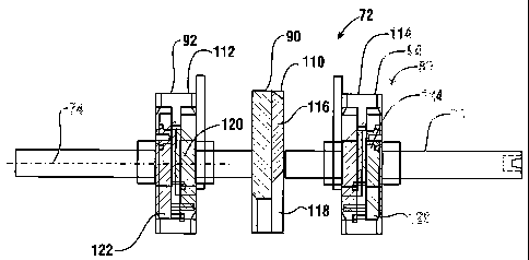
As shown in Figure 2 the outer bounding surface 80 of the picking
menlber includes an outer surface 110 of cylindrical portion 90, as well as
outer surface 112 of cylindrical portion 92 and outer surface 114 of
cylindrical
portion 94. Outer surface 110 includes thereon a ribbed relatively high
friction
portion 116. The balance of the outer surface 110 has a relatively lower
friction portion 118. High friction portion 116 applies an engaging force to
the
end note bounding the stack which is generally sufficient to engage and move
the end note from the stack. The low friction portion 118 is generally enabled
to move relative to the end note without causing the note to be moved from the
stack. In the exemplary embodiment this construction facilitates reliably
picking a single note each tiine the picking meinber is rotated one turn. This
construction further provides spacing between notes sequentially picked from
the stack. Such spacing facilitates identifying and handling of notes.
Outer surface 112 of cylindrical portion 921ikewise includes a ribbed,
relatively high friction portion 120 on the outer surface thereof. Outer
surface
112 also includes a relatively lower friction portion 122 which surrounds the
high friction portion. The angular position of liigh friction portion 120
generally corresponds to high friction portion 116 on the central portion 90.
As is the case with the other relatively high and low friction portions, high
friction portion 120 applies force to the end note generally sufficient to
engage
and move it from the stack, while the relatively lower friction portion is
enabled to move in engagement with the end note without causing it to be
disposed from the stack. Similarly as shown in Figure 2 cylindrical portion 94
also includes a generally high friction portion 124 and a generally lower
friction portion 126. The high and low friction portions on the cylindrical
portion 94 angularly correspond to the high and low friction portions on the
other cylindrical portions of the picking member.
As most clearly shown in the partial cross sectional view in Figure 3,
within the high .fiiction portion 120 of cylindrical portion 92, is an arcuate
CA 02517719 2005-08-29
WO 2004/081884 PCT/US2004/007211
19
segment 128. Arcuate segment 128 occupies a portion of the axial width of
the cylindrical portion toward the outboard side of the picking member. The
arcuate segment 128 is supported on a movable meinber 130. Movable
mena.ber 130 as later discussed in detail, is movable relative to the
cylindrical
portion and the picking member in a manner which enables arcuate segment
128 to move radially outward relative to the bounding surface bounding the
picking member. In the exemplary embodiment the cylindrical poi-tion 92 is
generally I-shaped in transverse cross section and includes a central web
portion 132. The web portion 132 terminates in cross section in a flange
portion 134 which supports the outer surface 112 thereon. The movable
member 130 is movable in a recess 136 on a first longitudinal side of the web
member 132.
A cam 138 is positioned in a recess 140 which extends on opposed
longitudinal side from recess 136. Cam 138 is in supporting connection with
the shaft 88. Cain 138 is also in supporting connection with a support member
portion 142. The support member portion 142 operates to hold the cain 138
stationary as the shaft 88 and cylindrical portion 92 rotates.
Cylindrical portion 94 includes structures which are generally a mirror
image of those associated with cylindrical portion 92. The high friction
portion of outer surface 114 includes an arcuate segment 144 which is
supported on a movable menlber 146. The movable member 146 is positioned
in a recess 148 which is bounded by a web portion 150 and a flange portion
152 of cylindrical portion 94.
A cam 154 is positioned in a recess 156 on an opposed longitudinal
side from recess 148. Cam 154 is in supporting connection with the shaft 88
and is held stationary relative to the shaft by a support member portion 158.
As the operation of the cylindrical portions 92 and 94 of the picking
meinber are similar, an explanation of the operation of the picking member
will be described with reference to cylindrical portion 94. As best seen in
Figure 4, the segment 144 extends through an opening 160 in the flange
CA 02517719 2005-08-29
WO 2004/081884 PCT/US2004/007211
portion 152 of cylindrical portion 94. The exemplary movable member 146 is
generally horseshoe shaped and is supported on the picking member through a
pivot connection 162. The pivot connection supports the movable imrnber
146 through the web portion 150.
5 The cam 154 is bounded by a cam surface 164. A cain follower
portion 166 is supported on the movable member 146 at an end opposed of the
arcuate segment 144. The cazn follower portion extends through an opening
168 in the web portion 150. This enables the cam follower portion 166 to
engage the cam surface 164 of the cam 154. As can be appreciated, this
10 arrangeinent enables the position of the arcuate segment 144 to be
controlled
as the picking member rotates due to the engagement of the cam follower 166
with the cam surface 164.
The overall operation of the exemplary picking member 72 is
explained with reference to Figures 5 and 6. As indicated in Figure 5, during
15 normal operation of the picking member the high friction portions on the
picking members engage an end note 78 bounding the stack. The high friction
portions move the note generally engaged and at the same speed as the picking
member, past the stripping member 82 so that the end note is moved from the
stack. During this normal operation the note moves in synchronized relation
20 with the movement of the outer bounding surface 80 of the picking member
82. As a result during normal operation the velocity of the end note indicated
by arrow N corresponds generally to the velocity of the outer surface 80 of
the
picking meinber represented by arrow P. Arrow F corresponds to the direction
of the force applied to the stack which holds the end note 78 in engaged
relation with the picking member 72.
Figure 6 represents the operation of the picking member 72 of the first
exemplary embodiment when an end note 78 fails to niove in coordinated
relation with the picking member. In such circumstances the velocity and
displaceinent of the picking ixiember is greater than the corresponding
velocity
and movement of the end note 78. The high friction arcuate segments 128,
CA 02517719 2005-08-29
WO 2004/081884 PCT/US2004/007211
21
144 which serve as engaging portions, because they are enabled to move
relative to the picking member 72, tend to maintain engaged relation with the
end note. This is represented by the arcuate segment 144 in Figure 6. Because
the engaging portion of the arcuate segment 144 remains engaged with the eaid
note and is movable relative to the picking member, wlzen the angular
movement of the picking member exceeds the movement of the engaging
portion of segment 144, the segnlent 144 moves radially outward relative to
outer bounding surface 80. The movement of the engaging portion further
radially outward relative to the axis of rotation 174 increases the engaging
force on the end note urging it to move from the stack. As can be appreciated
from the later detailed description of the movable member, the engaging
portions tend to move further radially outward providing increasing engaging
force, with an increase in difference between the movement of the picking
member and the engaging portion. This increasing force on the end note tends
to cause the end note to begin moving past the stripping meinbers 82 so that
the note can be picked. As the end note begins to move in coordinated relation
with the picking member, the engaging portions may begin to move radially
inward. In the exemplary embodiment the action of the cam follower portion
and the cain surface operate to assure that the engaging portions are moved
radially inward to the level of the outer bounding surface 80 by the time the
engaging portions rotate to a position adjacent to the stripping members 82.
This assures that the engaging portions and the notes are not damaged.
Figures 7-10 show the exemplary operation of the picking member 72
with regard to cylindrical portion 94 of the picking member. It should be
understood that cylindrical portion 92 is a mirror image thereof and works in
a
similar manner during picking. As represented in Figure 7, the picking
member 72 rotates in the direction of arrow P. Assuniing that an end note
engaged with the engaging portion which is included on segment 144= is not
moving in synchronization with the picking member, the segment 144 rotates
in a first direction about pivot connection 162. This results because the
CA 02517719 2005-08-29
WO 2004/081884 PCT/US2004/007211
22
segment 144 is engaged with the note and the angular movement thereof does
not correspond to the angular movement of the picking member 72 about the
axis 74. Segment 144 moves radially outward relative to axis 74. The radially
outward movement of segment 144 is limited by the engagemnt of the cam
follower portion 166 with the cam portion 164 of cam 154.
As can be appreciated, the outward movement of the engaging portion
on segment 144 applies increasing engaging force on the end note responsive
to the end note not moving with the picking member. In addition the engaging
portion of segment 144 operates to move further radially outward with an
in.creasing difference between the movement of the picking member and the
movement of the note. This outward movement may continue until the
segment 144 reaches the full extent of its travel as limited by the cam
surface.
As shown in Figure 8, if the end note has not initially moved in
coordinated relation with the picking member, the engaging portion of the
arcuate segment 144 will generally remain extended radially outward relative
to the outer bounding surface of the picking member as the picking member
further rotates. This provides additional force tending to assure that the
note is
moved from the stack. It should be appreciated that once the note begins
moving, if note movement begins to exceed that of the picking member, the
engaging portion of the arcuate segment 144 will begin to retract radially
inward toward the outer bounding surface 80. Generally however once the
engaging portion has extended radially outward, it will remain outwardly
extended to the extent permitted by the engagement of the cam follower
portion 166 with the cam surface 164.
As shown in Figure 9, as the picking member 72 rotates further toward
the position where the engaging portion of the arcuate segment 144 approaches
the stripping members, the profile of the cam surface 164 causes the cam
follower portion 166 to cause the movable member 146 to rotate relative to the
pivot connection 162. As shown in Figure 9 the cam surface tends to rotate
the movable member 146 in a generally opposed rotational directioil about
CA 02517719 2005-08-29
WO 2004/081884 PCT/US2004/007211
23
pivot connection 162, a direction in which the movable member rotates to
extend the arcuate segment. As a result, as the picking member rotates so that
the arcuate segment approaches the stripping member, the arcuate segment
tends to move radially inward toward the outer bounding surface 80.
As shown in Figure 10 once the picking member 72 has rotated to the
point where the engaging portion of segment 144= is in abutting relation witli
the stripping meinber, the operation of the cam surface 164 and the cam
follower portion 166 has caused the engaging portion to be retracted through
movement of the movable meinber 146. The outer surface of segment 144 at
this point is moved to generally conform with the outer bounding surface 80 of
the picking member. In addition as the engaging portion on the segment 144
retracts radially inward, the engaging portion applies a decreasing engaging
force to the end note as the end note is moved between the picking member
and the stripping member. This decreasing force not only avoids collisions
between the engaging portion and the stripping members, but it also prevents
possible damage to the mechanism as well as to the notes being picked.
As shown in Figure 10 the exemplary embodiment includes a stop
portion 170 on the movable member 146. The stop portion 170 engages a
surface 172 bounding recess 148. The stop portion prevents the engaging
portion on the segment 144 from being moved radially inward substantially
beyond the outer bounding surface 80 of the picking member.
As can be appreciated this exemplary embodiment of the picking
member provides increasing engaging force on the end note responsive to the
end note not moving with the picking member. As a result additional picking
force is applied in only those circuinstances where it is required to move the
end note from the stack. In circuinstances where notes are soiled, have high
surface tension or are of slippery consistency, additional moving force is
usually automatically applied. Further this exemplary form of the picking
member also enables compensating for wear or reduced friction with soiling
that may result from extended use of a picking member. In this way the
CA 02517719 2005-08-29
WO 2004/081884 PCT/US2004/007211
24
exemplary forin of the picking member is able to compensate for those
conditions which might otherwise result in a decrease in note picking
reliability.
It should further be understood that while in the exeanplary form of this
picking meinber the engaging portion is moved radially outward and applies
additional picking force based on the relative movement between the end note
and the picking member, in other embodiments other approaches may be used.
Such approaches may include for example, other devices and systems for
determining a difference in relative movement between the notes being picked
aiid the picking member, and moving in engaging portion to apply additional
engaging force in response thereto. Although the exeinplary form of the
invention uses a mechasiical type system to accomplish this, electronic and
electromechanical systems may be used in other embodiments.
A further useful aspect of the exemplary form of the first embodiment
of the picking member and its operation in connection with dispensing
mechanisms, is that it may be readily retrofit to an existing automated
banking
machine. The exeinplary form enables a service technician to access an
interior area of an ATM such as by unlocking a door to a secure chest portion.
Once access is gained to the note handling mechanism, the technician may
remove an existing picking member which does not include the features of the
radially movable engaging portions, and to install a picking meinber 72 in
place tllereof. In the exemplary embodiment the support member portions
142 and 158 are configured to engage existing surfaces within the housing of
the ATM so as to hold the cams stationary as the picking member rotates.
Once installed in the ATM, the door to the secure chest portion is closed and
locked.
Picking member 72 is constructed to have the same general profile as
picking members that do not incorporate the exemplary enhanced picking
features. Thus, installation of the exemplary picking member is readily made
CA 02517719 2008-08-12
WO 2004/081884 PCT/US2004/007211
to improve the operation of the machine. It should further be understood that
the programming of the controller 22 also often need not be changed to
acconmzodate the installation of the picki.ng menYber 72. Except as described
herein, the operation of the piclcing niember 72 is similar to that of a
pick:ii7g
5 member wluch may be replaced in terms of moving and retracting notes.
Altenxative enibodiments of the automated baiiking machine may
include other types of slieet dispensing mechanisnis. Features of an
alterrnatiire
sheet dispensing mechanism 210 are described in connection with Figures 18-
21. Sheet dispenser 210 operates based on principles siniilar to those
10 described in connection with the first embodiment except as specifically
described herein.
Sheet dispenser mechanisn1210 includes a rotatable picking member
212. Picking member 212 includes a shaft portion 214 that extends along a
central axis schematically indicated 216. In the exemplary embodiment shaft
15 portion 214 is rotated about axis 216 by a drive such as a stepping motor
which is not separately shown. The pichdng member may alternatively be
referred to herein as a picker member.
Picking member 212 includes a middle disk portion 218. Middle disk
portion 218 in the exemplary embodinlent is in fixed connection with the shaft
20 portion 214 and rotates therewith. Picking meniber 212 further includes an
outboard disk portion 220 which is disposed from the middle disk portion on a
first axial side. Outboard disk portion 220 is also in fixed connection with
the
shaft portion 214 and rotates therewith. An outboard disk portion 222 is
disposed on an opposed axial side of middle disk portion 21 s. Outboard disk
25 portion 222 is also in fixed connection with the shaft portion and rotates
therewith. Because the nziddle disk portion 218 and the outboard disk portions
2?0 and 222 are each in fixed engagement with the shaft portion, they
maintain their relative angl.zlar positions as the shaft portion is rotated
during
the picking of notes.
In the exemplary embodiment, middle disk portion 21 S is comprised of
CA 02517719 2005-08-29
WO 2004/081884 PCT/US2004/007211
26
a generally rigid plastic material. The middle disk portion includes a low
friction arcuate surface 224 that extends angularly around a substantial
portion
of the middle disk portion. Low friction arcuate portion 224 has extending
therein a recess (not separately sliown). A band 226 of generally higher
friction resilient material extends around the middle disk portion in the
recess.
The band 226 and recess include an enlarged area 228 in which the band
extends across most of the outer surface of the middle disk portion. As later
described in detail, the enlarged area 228 of the band serves as a high
friction
arcuate segment that facilitates the picking of notes from a stack.
Outboard disk portion 220 in the exemplary embodiment is also
comprised of generally rigid low friction material. Outboard disk portion 220
includes an outer surface 230 which includes a recess therein (not separately
shown). A band 232 of resilient material extends in the recess and extends
around the entire circuinference of the outer surface. The band 232 includes a
high friction segment 234. The high friction segment 234 corresponds in
angular position to at least a portion of the enlarged area 228 on the middle
disk portion. In the exemplary embodiment of outboard disk portion 220,
flange portions 236 bound the recess and the band 232. The flange portions
236 extend further radially outward relative to axis 216 than the outer
surface
of the band 232 except in the area of the high friction segment 234. In the
area
of the high friction segment the band 232 extends radially outward beyond the
radial height of the flange portions 236 so as to facilitate picking.
Outboard disk portion 222 is similar in structure to outboard disk
portion 220. Outboard disk portion 222 includes an outer surface 238 which
includes a recess and in which a band 240 extends. The outer surface 238
includes flange portions 242 which bound the recess and the band. Band 240
includes a high friction segment 244 which extends radially outward beyond
the flange portions. High friction segment 244 is generally aligned angularly
with high friction segment 234 on outboard disk portion 220.
A stripping member 246 is positioned in opposed engaging relation
CA 02517719 2005-08-29
WO 2004/081884 PCT/US2004/007211
27
with the middle disk portion 218. In the exemplary embodiment the stripping
member 246 comprises a roll which is supported on a shaft 248. The stripping
member 246 has in connection therewith a one-way clutch which may operate
in the manner previously described. The clutch operates to resist rotation of
the stripping member in a direction in which the stripping member is urged to
move by engagement with the middle disk portion, but enables the stripping
member to rotate readily in an opposed direction so as to enable the return of
notes into the stack. In the exemplary embodiment stripping member 246 has
a guide member 250 that extends in overlying relation thereof. The guide
member includes an upper surface which has a contour that facilitates the
directing of notes into the nip area where the stripping member 246 engages
the middle disk portion (see Figure 20).
In the exemplary embodiment the stripping member 246 is positioned
relative to the middle disk portion 218 such that the surface of the stripping
member is in opposed engaging relation with the surface of the low friction
arcuate portion 224 of the middle disk portion. As a result the stripping
meinber 246 which is biased to engage the middle disk portion in a manner
later discussed, generally slides readily relative to the middle disk portion
except when the suface of the stripping member is engaged in the enlarged
area 228. When the enlarged area 228 is in abutting opposed relation with the
stripping member, the end note bounding a stack of notes is stripped from the
other notes in the stack in a manner that is later discussed.
As shown in Figure 18 a carry away member which in the exemplary
embodiment comprises a roll 252 is also mounted in opposed engaging
relation with the middle disk portion 218. The carry away roll 252 is
supported on a shaft 254 and is biased to engage the middle disk portion. The
carry away roll 252 is aligned with the area of the recess in the middle disk
portion that extends about the entire circumference of such disk portion. As a
result the carry away roll generally remains in engagement with the resilient
band 226 throughout the entire rotation of the middle disk portion except
CA 02517719 2005-08-29
WO 2004/081884 PCT/US2004/007211
28
during the time that a note is moving therebetween. The exemplary form of
carry away roll 252 is disposed downward and in an angular direction away
from the strippiilg area in which the stripping member 246 engages the middle
disk portion. This is shown in Figure 20. As a result in the exemplary
embodiment the carry away roll operates to engage a note that has been
separated from the stack by the action of the stripping member and the
enlarged area 228, and moves the separated note responsive to the movement
of the picking member so that the separated note is moved away from the
stack. In some embodiments this may avoid the need for a separate drive
device for carry away rolls, as the movement of the picking meinber itself
drives the carry away roll to move separated notes away from the stack.
As shown in Figure 18 a lower housing wall 247 supports a support
member 249 thereon. Support member 249 includes slots 251 and 253 therein
which accept shafts 248 and 254 therein, respectively. Wa11247 also has
integrally formed therein leaf springs portions 243, 245. Leaf spring portion
243 biases shaft 245 and stripping meinber 246 toward middle disk portion
218 by biasingly engaging a clip portion 241 of member 250. Spring portion
245 acts on shaft 254 to bias carry away rol1252 to engage the iniddle disk
portion. The ends of each shaft 248 and 254 opposed of the roller is mounted
in supporting connection with the housing through a releasable pivot
connection (not separately shown) wllich enables each roll to maintain biasing
engagement with the middle disk portion. The pivot connection enables each
of the stripping member and carry away meinber and their respective shafts to
be released from operative supporting connection from the housing and
replaced. Of course, in other embodiments otller releasable mounting
arrangements may be used.
As shown in more detail in Figure 19 the enlarged area 228 on the
middle disk portion 218 includes a leading area 256. The leading area 256 has
extending transversely adjacent thereto, an arcuate projecting portion 258.
CA 02517719 2005-08-29
WO 2004/081884 PCT/US2004/007211
29
The arcuate projecting portion 258 in the exemplary embodiment comprises an
extension of the outer surface of the middle disk portion 218. The arcuate
projecting portion 258 extends radially outward relative to the wilis beyond
the
outer surface of the band 226 in the leadi.n.g area 256. The arcuate
projecting
portion is also disposed adjacent to but transversely away from a stripping
area
260 in which the stripping menlber 246 engages the leading area 256 of the
enlarged area 228 of the band.
In the exemplary embodiment the arcuate projecting portion 258
arcuately extends up to a driving area indicated 252 in the enlarged area 228
of
the band. In the driving area the band extends further radially outward
relative
to the leading area 256. The driving area 252 generally corresponds angularly
to the positions of the high friction arcuate segments 234 and 244 on the
outboard disk portions 220 and 222 respectively. As shown in Figure 19 the
enlarged area 228 of the resilient band includes a ribbed desigli that is
consistent across the leading area 256 and the driving area 262. In some
embodiments the ribbed design may serve to provide desirable frictional
properties for the band. Of course in other embodiments other designs for
tread surfaces as well as other types of frictional materials may be used.
The operation of the alternative exemplary sheet dispensing
mechanisin 210 is now described with reference to Figures 19-21. A stack of
notes schematically indicated 264 is bounded by an end note 266. In
exemplary embodiments the stack 264 may generally be contained within a
removable canister or other suitable holding container. Of course alternative
approaches for holding a stack of notes may also be used. The stack 264 is
biased in the direction of Arrow F in Figure 20 by a suitable biasing device
so
as to urge the end note 266 of the stack to engage the picking member
including disk portions 218, 220 and 222.
As in the previously described embodiment the end note 266 is
separated from the stack by rotation of the picker member 212 in the direction
of Arrow R as shown in Figure 20. The rotation of the picking member 212
CA 02517719 2005-08-29
WO 2004/081884 PCT/US2004/007211
generally does not cause the end note 266 to move substantially relative to
the
stack except when the driving area 262 of the middle disk portion and the high
friction segments 234 and 244 of the outboard disk portions are engaged with
the end note. This is because of the relatively low friction engagement
5 between the outer surfaces of the disk portions and the end note in the
other
areas about the circumference of the disk portions.
As the picking member rotates a full rotation the end note 266 is
moved relative the stack. In the exemplary embodiment rotation of the picking
member brings the leading area 256 adjacent the forward boundary of the
10 enlarged area 228 of the band 226 on the middle disk portion into
engagement
the outer surface of the stripping member 246 in the stripping area 260 as
shown in Figures 20 and 21. The forces of the relatively moving leading area
and non-moving outer surface of the stripping member acting on a leading
edge area and opposed sides of the end note cause the note to begin to be
15 separated from and in many cases to begin moving responsive to the rotation
of the picking member relative to the stack. However, in the exemplary
embodiinent while the leading edge area of the end note 266 is engaged with
the leading area 256 of the picking member, the end note is also engaged with
the surface of the transversely adjacent arcuate projecting portion 258 of the
20 middle disk portion. This engagement of the end note with the arcuate
projecting portion in a support area that is adjacent, but somewhat axially
transversely disposed from the stripping area, serves to support the note and
to
reduce the risk that the leading edge area of the note will be deformed such
as
crumpled or nicked by the opposed forces imparted to the note by the action of
25 the enlarged area of the band and the stripping member. Thus the surface of
the arcuate projecting portion serves to prevent excessive deformation of the
note along a direction which the note is urged to move by the picking meanber
due to the opposing force applied by the stripping member. The angled treads
of the exemplary picking member underlying the leading edge area of the note
30 in opposed relation of the stripping member further serve to enable
relative
CA 02517719 2005-08-29
WO 2004/081884 PCT/US2004/007211
31
movement of the picking member with regard to the note without causing
potentially damaging deformation.
Furtlier rotation of the middle disk portion in the direction of Arrow R
causes the arcuate projecting portion to rotate beyond the stripping area
where
the stripping meinber 246 engages the enlarged area 228. Further such
rotation causes the driving area 262 which has an outer surface that extends
further radially outward from the leading area to engage the adjacent surface
of
the end note. This imparts additional force urging the end note 266 to move
relative to the stack. Further at generally the same time during the rotation
of
the picking member, the high friction arcuate segments 234 and 244 on the
outboard disk portions also act on the end note further urging it to move
relative to the stack. These forces acting on the end note cause the end note
to
move further in intermediate relation between the band 226 and the stripping
member 246 and to engage the carry away ro11252. The end note 266 moves
in engaged intermediate relation between the band 226 on the middle disk
portion and the carry away rol1252 which further helps to move the end note
away from the stack and the picking member.
Of course as previously described in connection with the other
exemplary embodiment, if a double note is sensed as having been picked, the
controller may be operative to cause the direction of the picking member to be
reversed. This is done before the note is disengaged from the picking member
so as to move the note back into the stack. Thereafter the controller may
operate to cause the picking member to again attempt to pick the end note so
that it is separated from other notes in the stack.
The features described in connection with the sheet dispensing
mechanism 210 may prove useful in circumstances where the notes or other
sheets that are to be picked may tend to be crumpled or have the leading edge
thereof nicked or torn by the forces imparted to the sheet as a result of
stripping action. In the exemplary enzbodiment the forces imparted to the
sheet initially by the leading area serve to move a central portion of the
leading
CA 02517719 2005-08-29
WO 2004/081884 PCT/US2004/007211
32
edge of the sheet into the nip formed by the middle disk portion and the
stripping member, while a transversely adjacent area is supported by the low
friction arcuate projecting portion, is operative to reduce the likelihood of
nicking or crdtnipling the notes in the area where the stripping forces are
applied to the notes. Such features may be particularly helpful in the case of
thin, flexible and/or fragile notes or media that is susceptible to cruinpling
or
tearing. Further, avoiding deformation of the leading edge of the notes also
reduces the risk that such a deformed or damaged note will be sensed by a
doubles detector as a double or other unrecognizable note. This reduces the
risk that such a note will be retracted into the stack. Such retraction of a
properly picked single note may not be necessary. Further in some
embodiinents a return to the stack and additional attempts to pick the note
from the stack may result in further damage or tearing of the note. This may
pose additional complications and/or may cause the machine to be placed out
of service.
It should be understood that the structures shown in comlection with
the sheet dispensing mechanism are exemplary and in other embodiments
other approaches of providing stripping action while simultaneously providing
support in a support area so as to minimize sheet damage may be used. For
example in some embodiments additional surfaces or devices for providing
support may be provided on the picking member, the stripping member or on
other structures. Further it should be understood that although in the
described
embodiment a single stripping member is utilized, the principles described
may be applied to devices in which multiple stripping members are used.
As sliown in Figure 18, the exemplary einbodiment of the sheet
dispensing mechanism 210 also provides for ready change of the picking
member 212. In this exemplary embodiment the housing 268 which supports
the sheet dispensing mechanism includes a tab portion 270 thereon. Tab
portion 270 includes a bushing 272 adjacent to a free end thereof. Bushing
272 is adapted to accept therein a cylindrical projecting portion at the end
of
CA 02517719 2005-08-29
WO 2004/081884 PCT/US2004/007211
33
shaft portion 214. This projecting portion is readily releasibly engageable in
the bushing 272 in the exemplary embodiment. The end of shaft portion 214
opposed of the bushing 272 is releasibly engageable with a, drive shaft 274.
In
the exemplary enlbodiment the drive shaft 274 includes a cylindrical
projecting portion that extends in a mating recess within the shaft portion
214.
A driving projection in operative connection with the drive shaft 274 is
accepted in a corresponding recess in the shaft portion 214 so as to provide
generally solid rotational driving engagement between the drive shaft 274 and
the picking member 212. As a result, in the described exemplary embodiment
the picking member 212 may be replaced by deforming the resilient tab
portion 270 outward relative to the housing 268. This provides additional
clearance such that the shaft portion 214 may be disengaged from the drive
shaft 274 and the bushing 272. Thereafter a substitute picking member may be
inserted and will be held in place by the inward biasing force of the tab
portion
270. Of course this approach is exeinplary and other approaches may be used.
In the exemplary embodiment, before the picking member is removed
from supporting connection with the housing it is generally advisable to
dispose the stripping member and carry away member away from the iniddle
disk portion. This provides greater access to the picking member and enables
it to be moved out of the housing for inspection or replacement purposes. In
addition, it is occasionally necessary to replace the stripping member and/or
carry away member for purposes of ensuring the reliable operation of the
machine. As can be appreciated, in some situations the stripping member may
become worn over time due to repeated contact with note surfaces.
Alternatively or in addition, the surface of the stripping member may become
contaminated due to the presence of dirt or other material on the notes being
dispensed. The surface of the cany away member may also become
contaminated for similar reasons which may reduce its efficiency in engaging
and urging notes to move between the carry away meniber and the central disk
portion.
CA 02517719 2005-08-29
WO 2004/081884 PCT/US2004/007211
34
When it is desired to move the stripping member 246 away from the
middle disk portion 218, a servicer gains access to the appropriate area of
the
housing 268. This is done in the exemplary embodiment by moving the
currency holding canister or cassette which houses a stack of bills or other
sheets and which enables the end note in the staclc to be biased into adjacent
relation with the picking member. Once the sheet holding structure has been
removed from the housing, a servicer may manually deform leaf spring portion
243 so as to move the fiee end of the leaf spring downward such that it no
longer holds the stripping member 246 in adjacent relation of the picking
member. This can be facilitated in the exemplary embodiment by the servicer
applying a force to the stripping member or the shaft 248 so as to initially
move the stripping member slightly toward the axis of rotation of the picking
member. This enables the leaf spring portion to disengage and to be moved
such that the free end thereof is disposed below the shaft 248 and the clip
portion 241 of bracket 250. This enables the stripping member 246 to be
moved axially away from the axis of rotation of the picking member outward
through the slot 251. As previously discussed, in the exemplary embodiment
the shaft 248 is in supporting connection with the housing through a pivot
mounting such that the stripping member moves arcuately away from the axis
of the picking member. Of course this approach is exemplary, and in other
embodiments other approaches may be used.
In the position with the stripping member moved away from abutting
relation with the picking member, a servicer is enabled to maintain the
stripping member disposed away from the axis of the picking member for
purposes of inspection or replacement of the picking member. Alternatively,
in the exemplary embodiment the stripping member and shaft assembly is
enabled to be removed from its mount for purposes of inspection or
replacement. As a result, a servicer is enabled to replace a stripping member,
guide member, shaft or entire assembly, as required. In addition in the
exemplary enibodiment, the stripping member has an integral one-way clutch
CA 02517719 2005-08-29
WO 2004/081884 PCT/US2004/007211
which, as previously discussed, facilitates dealing with situations where
multiple sheets are inadvertently picked.
Once the desired parts are replaced, the shaft 248, stripping mernber
and guide ineinber assembly may be engaged with the mounting mechanism to
5 again place them in supporting connection with the housing, and the
stripping
member moved toward the axis of rotation of the picking member. As this
occurs, the shaft 248 moves into the slot 251. Once the stripping member is in
the operative position, the leaf spring portion 24=3 which is biased downward
by the clip portion 241 as the stripping member moves into the operative
10 position, is enabled to move upward to engaged the clip portion. This
action
of the leaf spring portion holds the stripping member in the operative
position
in biased abutting relation with the central disk portion.
A mounting approach similar to that used for the stripping member
may be used for the carry away ro11252. The carry away roll, which is
15 transversely disposed from the stripping member and disposed in the
direction
of note movement from the point of engagement of the stripping member with
the central disk portion, is biased toward engagement with the middle disk
portion and held through the action of leaf spring portion 245. Leaf portion
245 in the operative position has a free end which engages shaft 254 which is
20 in supporting connection with the carry away roll. In the operative
position,
shaft 254 extends in slot 253 so as to maintain its position relative to the
central disk portion. Shaft 254 at an end opposed of the carry away roll is
also
movably mounted in supporting connection with the housing through a mount
which is not separately shown. Of course this approach is exemplary, and in
25 other embodiments other approaches maybe used.
In the exemplary embodiment the carry away rol1252 is enabled to be
moved away from the axis of the picking member. This is accomplished by a
servicer deforming leaf spring portion 245 so that is no longer engages shaft
254, so as to hold the carry away member in the operative position. In the
30 exemplary embodiment this may be facilitated by the servicer biasing the
shaft
CA 02517719 2005-08-29
WO 2004/081884 PCT/US2004/007211
36
and/or carry away member slightly towards the picking member while
deforming the leaf spring portion 245 such that the free end thereof may pass
underneath shaft 254. Shaft 254 may then be moved rearward away from the
axis of rotation of the picking member through the slot 253. Again, in this
position the carry away member may be maintained so as to provide access for
inspecting or replacing the picking member. Alternatively in the exemplaty
embodiment, the carry away roll may be replaced along with the shaft 254 by
disengaging the shaft from its mounting mechanism.
When it is desired to return the carry away roll to the operative position
after service activities or replacement, the shaft 254 is returned to its
rotatable
mounting mechanism and the carry away ro11252 is moved toward the axis of
rotation of the picking member and into the slot 253. As this occurs, the leaf
spring portion 245 has the free end thereof biased downward until the shaft
254 passes the free end. Once the shaft 254 has moved sufficiently forward
toward the axis of the picking member, the free end of leaf spring portion 245
moves upward to hold the shaft into a position in which is biasly toward
engagement with the middle disk portion.
It should also be noted that this exeinplary approach has the advantage
that the carry away roll and stripping member may be disposed from the
support member 249. This also enables more ready replacement of the support
meinber in the event that the support member sustains breakage or wear. Such
replacement may be accomplished through the use of various fastener
mechanisms which are operative to releasibly hold the support member in
engagement with the housing. It should also be understood that in conducting
servicing activities in the exemplary embodiment, generally it will be
desirable
to move the stripping member and carry away roll to the operative position
once the picking meinber is in place in supporting connection with the drive
shaft 274 and the tab portion 272. However, in some circumstances servicers
may find it useful to move one or both of the stripping member and carry away
roll into the operative position and then to install the picking member into
CA 02517719 2005-08-29
WO 2004/081884 PCT/US2004/007211
37
engagement with the drive shaft and tab portion. The approach used will
depend on the circumstances and the nature of the servicing activity.
In an exemplary embodiment a note transport such as note transport 54,
includes features to reduce the risk that notes may become stuck or jammed in
the transport. As previously discussed in connection with Figure 1, note
transport 54 includes a plurality of continuous belts 56 which extend about
sets of rollers 58. It should be understood that the transport 54= may include
belts that extend the entire length of the transport or may have several belts
which span sections of the transport. In an exemplary embodiment the
continuous belts are arranged so that the transport includes a plurality of
generally parallel belt flights. These belt flights are represented in Figure
12
by belt flights 174, 176 and 178. Each of the belt flights extend along a
longitudinal direction of the transport, in which longitudinal direction
sheets
are moved. The belt flights are moved through operation of a drive or similar
moving mechanism which is controlled responsive to operation of the
controller 22 and which drives the rollers upon which the belts are supported.
As shown in Figure 12, disposed transversely intermediate of each
adjacent pair of belt flights, are projecting member portions 180, 182. As can
be readily seen from Figure 12, each of the belt flights has a first sheet
engaging surface represented by surface 184 of belt flight 174, which faces in
a first facing direction toward a sheet 186 which extends in the transport.
The
projecting member portions each include a second sheet engaging surface
represented by surface 188 of projecting member portion 180. The second
sheet engaging surface 188 faces in a second facing direction which is
generally opposed of the first facing direction. As will be appreciated the
first
and second facing directions in which the sheet engaging surfaces of the belt
flights and the projecting member portions extend respectively, are both
generally normal of the longitudinal direction in which the sheets move.
As can be appreciated from Figures 12 and 13, the configuration of the
CA 02517719 2005-08-29
WO 2004/081884 PCT/US2004/007211
38
first belt flights and the sheet engaging member portion is such that a sheet
that is moved into intermediate relation between the first sheet engaging
surface of the belt flights and the second sheet engaging surfaces of the
projection member portions, is deformed in a wavelike configuration so that
the sheet is engaged with the belt flights. As a result when the belt flights
move, the sheet 186 moves in engagement therewith.
As can be appreciated from Figure 14, the sheet transport 54 is enabled
to accept sheets such as a sheet 190 through openings such as opening 192. As
can be appreciated, from Figure 14, a sheet passing through the opening in the
projecting member portions moves in engagement with the first belt flights to
become trapped in sandwiched relation between the belt flights and the
projecting meinber portions. The sheet once trapped in this manner is caused
to be moved along with the belt flights to a desired location within the
machine responsive to signals from the controller.
As mentioned previously, occasionally sheets such as bank notes
become stuck in transports of this type. This may result due to various
conditions which prevent the notes from moving in coordinated relation with
the belt flights. In the exemplary embodiment conventional type belts which
have in the past been used in transports of this type are replaced with
alternative belts which reduce the risk that sheets will become stuck.
Specifically while prior belts have a generally smooth continuous sheet
engaging surface, the alternative belts used of the exeinplary form include at
least one longitudinally spaced projection which extends in the first facing
direction from the sheet engaging surface of the belt. In a more preferred
exemplary form such longitudinally spaced projections extend at spaced
intervals on the first sheet engaging surface of the belt. The presence of
such
longitudinally spaced extending projections engage sheets that might
otherwise not move in the transport and move tla.eni to the desired location.
Figure 11 shows an isometric view of belt flight 174 with the first sheet
CA 02517719 2005-08-29
WO 2004/081884 PCT/US2004/007211
39
engaging surface 184 thereof turned 180 degrees from that shown in Figure 13.
The first sheet engaging surface 184 includes a plurality of longitudinally
spaced projections 194. The projections 194 extend generally in the first
facing direction represented by arrow 196. In the exemplary embodiment, the
projections 194 are deformable, resilient and spaced from one another a
distance that is greater than the length of the sheets that are moved through
the
associated transpoa-t in the longitudinal direction. This enables a sheet to
extend between the adjacent longitudinally spaced projections. It should be
understood however that other embodiments may have projections with other
properties and the projections spaced more closely together. Other alternative
embodiments may have the projections spaced far apart, even to the extent of
including only one such projection on the continuous sheet engaging surface of
a belt.
In some embodiments all of the belts used in connection with a
transport may include projections thereon. However in some embodiments it
may be desirable only to replace certain belts with alternate belts including
such projections. For example in the transport including three belt flights
shown in Figure 13, it may be desirable only to replace the middle belt with
an
alternate belt. Alternatively it may be desirable to replace the two outward
belts with an alternate belt, leaving the middle belt as having a generally
smooth continuous outer surface. Various approaches to replacing the belts
may be taken depending on the particular type of documents being transported.
As shown in Figure 13 some embodiments may have multiple belts
arranged such that the projections that extend from the first sheet engaging
surfaces of the belts are generally transversely aligned. Iu this way each of
the
longitudinally spaced projections will maintain generally the same spaced
relation relative to the other projections as the belts are moved from the
transport. Alternate embodiments may have the belts installed such that there
is no predetermined relationship between the projections on each respective
adjacent belt. In each situation benefit is obtained as the projections
facilitate
CA 02517719 2005-08-29
WO 2004/081884 PCT/US2004/007211
movement of sheets in the transport.
It should be understood that the configuration of belt flight 74 with the
longitudinally spaced projections which extend across the first sheet engaging
surface of the belt is exemplary. In other enibodiinents other types of
5 projection configurations maybe used. For example, Figure 15 shows a belt
flight 198. Belt flight 198 includes bubble type projections 200. Figure 16
shows a further alternate belt flight 202 which has adjacent cone-like
projections 204. Figure 17 shows yet a further alternate belt flight 206. Belt
flight 206 includes rainp-like projections 207. It should be understood that
10 these belt and projection configurations are exemplary and in other
embodiments other configurations may be used.
The exemplary form of the transport improvements is designed for use
in connection with existing transports which move sheets such as bank notes
in an automated banking machine. Belts which include the improvement are
15 made to extend about existing sets of rollers within the machines and to
replace existing transport belts which have generally smooth continuous sheet
engaging surfaces about the entire periphery thereof. To improve the
performance of the transports in such machines, a service person must open
the housing of the machine such as by unlocking and opening a door of a
20 secure chest. The service person is then enabled to remove the existing
transport belt from a set of rollers which support and move such belt. With
the
prior belt removed from the transport, an alternative belt of one of the types
described herein including longitudinally spaced projections is installed in
supporting comiection with the set of rollers. The service person may then
25 close and lock the door of the secure chest of the ATM. Sheets may be then
moved in the transport urged not only by the relatively smooth portions of the
sheet engaging surface of the belt, but further urged to move by engagement
with the projections thereon. As can be appreciated, the projections on the
belts provide additional urging force that is generally sufficient to move
sheets
30 that otherwise might slip or become stuck in a transport.
CA 02517719 2008-08-12
WO 2001/082884 PMUS20041007211
41
It should be appreciated that in the exemplary embodiment, the
alternate belts described may be used in connection with transport 54 as well
as transport 60. The principles of the invention may also be applied tc+ othFr
devices which move sheets within the machine. For example belts which
include longitudinally spaced projections of the type described herein may be
used in connection with a. system for moving stacks of sheets such as is shown
in U.S. Patent No. 5,507,45 l.
In such transports the projecting member
portions comprise moving belt flights whicli n7ove in coordinated relation
with
the facing belt flights and serve to transport stacks in between. Alternative
belts including projecting portions thereon may be used to move stacks of
sheets that are in between and enable movement of such stacks more reliably.
As is explained in the incorporated disclosure, such transports in whieh the
projecting member portions comprise moving belt flights enable reliably
moving stacks of notes or connected sheets such as passbooks and checkbooks
within an automated banking machine.
The principles of the present invention may also be applied to other
types of stack and sheet transports including for example, stack accumulation
and presentation mechanisms such as is found in U.S. Patent No. 5,435,542,
the disclosure of which is also incorporated herein by reference as if fully
rewritten herein. Of course the principles may be applied to other transport
mechanisms as well. It should be understood that the improved sheet
dispensing functions achieved tlirough utilization of one or more of the
principles described herein may be incorporated in automated banking
2 5 machines with the iniproved transport features to achieve improved
reliability
in moving and deliver.ing sheets within the automated banking machine. Of
course it should also be understood that in some einbodiments the iunproved
pick-ing capabilities will be implement.ed without the inYpraved transport
capabiiities and vice versa. The principles described herein may also be
applied to other configurations of picking members and devices as well as
CA 02517719 2008-08-12
WO 2001/081884 PCT/US2004/007211
42
sheet transports.
Thus the new and iniproved automated banking machine features
deseribpd herein aelzieve at lAast one of the above stated objectives,
elimina.tP
difficulties encountered in the use of prior devices and systems, solve
problems and attain the desirable results described herein.
In the foregoing description certain terms have been used for brevity,
clarity and understanding, however no unnecessary liniitations are to be
iniplied therefrom because such terms are used for descriptive purposes and
are intezzd.ed to be broadly construed. Moreover, the descriptions and
20 illustrations herein are by way of examples and the invention is not
limited to
the details shown and described.
In the following claims any feature described as a means for
performing a function shall be eonstrued as encompassing any means capable
of perforniing the recited function,
Having described the features, discoveries and principles of the
invention, the manner in which it is constructed and operated, and the
advantages and useful results attained; the new and useful structures,
devices,
elements, arrangements, parts, combinations, systems, equipment, operations,
methods, processes and relationships are set forth in the appended claims.