Note: Descriptions are shown in the official language in which they were submitted.
CA 02517932 2000-10-23
FIELD OF THE INVENTION
The present invention relates generally to the field of wireless data
communication
systems. More specifically, the present invention relates to a ftxed wireless
metropolitan area
network (MAN) that uses orthogonal frequency division multiplexing (OFDM)
carrier access
modulation configured to allow the consumer premise equipment (CPE) to utilize
an antenna
deployed internally within the consumer's premise, instead of requiring an
externally
accessible antenna that has a tine of sight transmission path to a base
station.
BACKGROUND OF THE INVENTION
Wireless data communication systems that utilize radio frequency (RF) signals
to
transmit and receive data are well known. Generally, wireless data
communication technology
has been applied to high performance long-distance communication systems such
as satellite
communications or microwave tower telecommunications, or to short-distance
local area
network (LAN) communication systems, such as a wireless LAN within a home or
office
environment. In the case of long-distance communication systems, a point-to-
point antenna
system is required and there must be a line-of-sight transmission path between
the
1
CA 02517932 2000-10-23
transmitter and the receiver. In the case of short-distance wireless LAN
communication, an
omni-directional antenna system can be utilized and a line-of-sight
transmission path is not
required because the distances are generally less than a mile. The reason for
this difference is
due to the fact that RF signals lose power rapidly over longer distances or
when transmitting
through obstacles such as buildings or walls.
A metropolitan area network (MAN)-is a.netw=ork-that-ear-cammu~icate-ovcr-
medium-- ---- - ------------ -
range distances of between about 1 to 40 miles as would be typically found in
providing
coverage over an entire metropolitan area. Digital subscriber loops (DSL)
services are a good
example of a wire-based MAN system that utilizes telephone wires as the
communication
medium. Cable modem systems are another example of a wire-based MAN system
that
utilizes coaxial cable as the communication medium. One of the primary
advantages of a
MAN system is that it allows for higher speed data communications as compared
to
conventional telephone modem speeds. The primary problem with such wire-based
MAN
systems is the cost of installing and maintaining the high-quality telephone
or coaxial cable
communication medium. A fixed wireless MAN system has the obvious advantage of
eliminating the costs associated with installing and maintaining a wire based
communication
medium.
Another advantage of a fxed wireless MAN system is that the wireless
communication
medium can be designed to provide for higher data communications speeds than
conventional
wire-based MAN systems. This advantage has caused the fixed wireless MAN
systems that
have been deployed to date to be designed for ultra high performance and
relatively expensive
dedicated networks. The market for these fixed wireless MAN systems has been a
small
number of customers who have high-speed data communication needs that
2
CA 02517932 2000-10-23
can justify the expense and complicated installation of such systems on an
individual basis. As
a result of the limited customer base and the need for ultra high performance,
the designs of
existing fixed wireless MAN systems have developed more along the lines of
high
performance long distance wireless communication systems.
While there are many factors to consider when designing RF communication
systems,
some of the more important factors to be considered in designing a fixed
wireless MAN
system are the assigned frequency, signal modulation and carrier access
modulation. Assigned
frequency refers to the range of frequencies or oscillations of the radio
signal that are available
to be used by the system. An example is the assigned band for AM radio signals
which operate
between 500 KHz and 1600 KHz. Signal modulation refers to the way in which
information or
data is encoded in the RF signal. An example is the difference between
amplitude modulation
(AM) radio signals and frequency modulation (FM) radio signals. Carrier access
modulation
refers to the way in which the assigned carrier frequencies are used to carry
the RF signal. An
example is the difference between using a single wide channel or multiple
narrow channels
over the same assigned frequency bandwidth.
For purposes of this invention, the design of a fixed wireless MAN system is
focused
on frequency ranges less than 10 GHz. Other medium-distance wireless
communication
systems have been developed, such as the local multipoint distribution system
(LMDS) that
operate at much higher frequency ranges, such as 28 GHz to 31 GHz. These
higher
frequencies are subject to different technical concerns and require larger
external antenna
systems that provide line-of-sight transmission paths from the top of one
building to another.
Because of the desire for higher data speeds, all of the existing fixed
wireless MAN
systems have utilized more complicated schemes for signal modulation. To
support faster
3
CA 02517932 2000-10-23
speed downstream transmissions, these systems typically use a 15-bit
quadrature amplitude
modulation (QAM) or 64-bit QAM to transmit downstream from the base station to
the CPE at
a data rate of at least 10 Mbps.
Unlike the many fixed wireless LAN systems that have been developed for short-
s distance communications and use a spread spectrum form of carrier access
modulation that
spreads one signal across the assigned frequency bandwidth, the relatively few
fixed wireless
MAN systems that have been developed to date have utilized mufti-carrier
modulation as their
carrier access modulation. In mufti-carrier modulation, the signal is divided
into several
parallel data streams and these parallel data streams are simultaneously sent
along different
slower speed channels and then reassembled at the receiver to produce a higher
effective
transmission rate. The mufti-carrier modulation scheme that has been
designated by the IEEE
standards committee to be used as the extension to the 802.11 wireless LAN
standard for high-
speed wireless data communications is known as orthogonal frequency division
multiplexing
(OFDM). The OFDM modulation scheme makes for a more efficient use of the
assigned
bandwidth and improves the ability to receive higher speed transmissions.
All of these more complicated modulation schemes for the existing fxed
wireless
MAN systems generally require more expensive equipment and more transmission
power at
each base station. To capitalize on the increased investment associated with
each base station,
existing fixed wireless MAN systems have been designed to minimize the number
of base
stations required to provide coverage for a given area. The radius of a
typical coverage area
for existing wireless man systems ranges between 10 to 30 miles.
Larger coverage areas are also used to minimize the need to reuse the same
frequency
channels in adjacent coverage areas. Because higher transmission powers are
used to
4
CA 02517932 2000-10-23
transmit at the higher data rates in ail of the existing fixed wireless MAN
systems, the higher
power signals prevent the reuse of the same frequency channels in adjacent
coverage areas and
can even preclude the reuse of the same frequency channels at distances up to
three to five
times the radius of the coverage area. Consequently, larger coverage areas
reduce the impact
of problems caused by the inability to reuse frequencies in adjacent coverage
areas.
The most significant disadvantage of larger sizes for the coverage area for
each base
station is the greater potential for signal loss or attenuation between the
base station and the
CPE. To counteract this potential signal loss over the larger distances and to
improve
reception at the higher power, higher transmission speeds, all of the existing
fixed wireless
MAN systems utilize a point-to-point antenna system that requires a line-of
sight transmission
path between the base station and an externally accessible antenna that is
connected to the
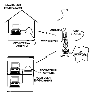
CPE. For example, see the prior art fixed wireless MAN system configuration of
FIG. 1
wherein the CPE within a single-user environment, e.g., a home, is connected
to an antenna
that is to the exterior of the single-user environment and where within a
mufti-user
environment, e.g., a small office, each CPE is connected to its own antenna
that is located
exterior to the mufti-user environment.
Given the relatively limited customer base and the need for all ultra high-
performance
that has dictated the development of existing fixed wireless MAN systems, the
use of
externally accessible antenna that provide a line-of-sight transmission path
is both necessary
and understandable. It will be desirable, however, to provide for a fixed
wireless MAN system
that does not require the use of an externally accessible antenna and could be
more broadly
deployed to provide higher data speeds more effectively to a larger number of
consumers.
5
CA 02517932 2000-10-23
SUMMARY OF THE INVENTION
The needs described above are in large measure met by a fixed OFDM wireless
MAN
system of the present invention. The fixed wireless access system generally
comprises a
consumer premise equipment (CPE) unit that is connected via an Ethernet
interface to a small
office/home office personal computer or local area network, and a base station
unit that is
connected via an Ethernet interface to a network. The CPE unit is located in a
premise for the
home or small office, has an antenna that is deployed internally within that
premise and is
easily user-installed. The base station unit is preferably tower-mounted
within a 1-10 mile
range of the CPE unit. The CPE unit preferably incorporates an internal,
integrated data
transceiver/switch that allows it to receive a digital signal from a computer
or network,
transform that signal to an analog format, and transmit the analog signal via
radio frequency
technology, preferably operating in the 2.5-2.686 GHz range, to a base station
unit. The base
station unit preferably incorporates an integrated data transceiver/switch.
Upon receiving the
signal, the base station unit transforms the analog signal back to a digital
signal and passes that
signal through the Ethernet connection to the personal computer, LAN, and/or
network.
Orthogonal frequency division multiplexing is used in the uplink and downlink
transmissions
between CPE units and base station units.
The fixed wireless access system transmits utilizing OFDM signals that
incorporate
OFDM symbols. The OFDM symbols are presented without a training symbol and are
detected in a symbol-by-symbol manner.
The fixed wireless access system utilizes a framed downlink transmission and
an
unframed uplink transmission.
6
CA 02517932 2000-10-23
BRIEF DESCRIPTION OF THE DRAWINGS
F1G. 1 provides an overview of a prior art fixed wireless MAN system utilising
external antennas.
FIG. 2 provides an overview of a fixed OFDM wireless MAN system of the present
invention utilizing internal antennas.
FIG. 3 depicts an overview of a single sector set-up within a cell of a fixed
wireless
access system of the present invention.
FIG. 4 depicts a cellular system of the present invention.
FIG. 5 depicts a standard, prior cellular re-use pattern.
FIG. 6 depicts a prior art cellular re-use pattern utilizing TDMA.
FIG. 7 depicts the preferred cellular re-use pattern of the present invention.
FIG. 8 depicts the layout of the upiink and downlink transmission slots used
with the
system of the present invention as well as the layout of the message packets
contained within
the slots.
FIG. 9 depicts, in block diagram format, the processing of a bit stream of a
data
package that is transmitted or received by radio frequency within the fixed
wireless access
system of the present invention.
DETAILED DESCRIPTION OF THE PREFERRED EMBODIMENTS
An overview of a fixed OFDM wireless metropoiitan area network (MAN) with
computer premise equipment (CPE) utilizing internal antennas of the present
invention is
shown in FIG. 2. As depicted, the fixed wireless access system 10 of the
present invention
7
CA 02517932 2000-10-23
may be configured for a single-user environment or a multi-user environment,
e.g., a local
area network. System 10 operates to transfer data from and to users of system
10 through use
of high-reliability radio transmission technology System 10 is especially
applicable to the
residential and small office/home office (SOHO) markets.
Referring now to FIG. 3, an overview of a single sector set-up within a cell
of fixed
wireless access system 10 is shown. As shown in F1G. 3, system 10 generally
comprises one
or more hosts, e.g., one or more host computers 12 and/or one or more local
area network
servers 13, which are connected to one or more customer premise equipment
(CPE) units 14
via an Ethernet connection 16. Each CPE unit 14 communicates with one or more
base station
units 18 within system 10 via radio frequency. Each base station unit 18 is
connected via an
Ethernet interface 19 to one or more of various types of networks 19, or
switching fabrics,
e.g., asynchronous transfer modes (ATM).
I. Svstem Components, Component Distribution and Component Reco ition
Each CPE unit 14 incorporates hardware necessary to implement Ethernet
communication with a user's personal computer 12 or LAN server, as well as
radio frequency
communication with base station units 18. That hardware is preferably
implemented, at least
in part, by use of field programmable gate array {FPGA) technology, or ASIC
technology, and
is preferably designed for a maximum power consumption of approximately 10
Watts. More
specifically, each CPE unit 14 preferably incorporates an integrated data
transceiver/switch
and one or more Ethernet connectors, e.g., lOBase-T RJ45 connector (lOBASE-T
is a
transmission medium specified by IEEE 802.3 that carries information at rates
up to 10 Mbps
in baseband form using twisted pair conductors, also called unshielded
8
CA 02517932 2000-10-23
twisted pair (UTP) wire). With respect to the integrated data
transceiver/switch, it should be
noted that individual components may be used without departing from the spirit
or scope of
the invention.
For ease of CPE unit 14 installation, the integrated data transceiver/switch
preferably
incorporates an integral directional antenna that allows CPE unit 14 to be
installed by a
customer near an associated host computer 12 and within the customer's
premise. The use of a
standard Ethernet connector 22 further enhances the ease of installation of
CPE unit I4 and
allows CPE unit I4 to easily be user-installed for communication with their
host computer 12
or local area network server 13. CPE unit 14 is preferably of a size and shape
so that it may be
positioned and/or mounted atop a desk, which again adds to the ease of a user
installation.
Base station unit 18 incorporates hardware necessary to implement Ethernet
communication with one or more of various types of networks 19, or switching
fabrics, e.g.,
asynchronous transfer modes (ATM), as well as radio frequency communication
with CPE
units 14. That hardware is preferably implemented, at least in part, by use of
FPGA
technology or ASIC technology and is preferably designed for a maximum power
consumption of approximately 100 Watts. More specifically, each base station
unit 18, similar
to each CPE unit 14, preferably incorporates an integrated data
transceiver/switch and one or
more Ethernet connectors, e.g., lOBase-T RJ45 connector. With respect to the
integrated data
transceiver/switch, it should be noted that individual components may be used
without
departing from the spirit or scope of the invention. Base station unit 18 is
preferably
additionally equipped with a global positioning system (GPS) receiver to
provide a time
reference, for system resolution and accuracy. A GPS time pulse is preferably
used by
9
CA 02517932 2000-10-23
system 10 to provide synchronization over the geographically distributed base
station units 18
to avoid interference between base station units 18. With respect to the
integrated data
transceiver/switch, it should be noted that individual components may be used
without
departing from the spirit or scope of the invention.
As per FIG. 3, base station unit 18 is preferably tower-mounted to facilitate
an
expanded, non line-of sight communication radius. The high system gain
provided by the
transmit levels, antenna gains, and receiver sensitivity allow for non line-of
sight operation of
base station unit 18. If base station unit 18 is mounted at the bottom of the
tower, an extended
length of coaxial cable is required between base station unit 18 and its
antenna. The longer
coaxial cable run produces more loss in the system gain and will reduce the
operational
distance for a given level of non line-of sight coverage.
Each base station unit 18 is positioned per a distributed cellular system 30,
see FIG. 4,
wherein each cell 32 preferably includes one or more sectors 34, and each
sector 34 preferably
includes one base station unit 18. FIG. 4 is a diagram of an exemplary
distributed cellular
system 30 wherein each cell 32 has six sectors 34. Each cell 32 preferably has
a
communication radius of approximately I to 10 miles, with a typical radius of
3 miles.
However, the use of a cellular, sectorized base station unit 18 deployment
does not restrict the
use of a single omni-directional base station unit 18. More specifically, it
is not necessary to
have a cell with multiple sectors to operate as a single cell operation. In
the instance of a small
geographic area, e.g., less than a three mile radius, where the potential user
base is low and a
single base station unit I8 could meet the data throughput capacity, a single
base station could
be installed with a high gain omni-directional antenna.
CA 02517932 2000-10-23
Once each CPE unit 14 and each base station unit 18 have been properly
installed,
each is capable of transmitting and receiving communication signals to and/or
from each
other. In the most basic of terms, the combined effect of radio frequency
communication
between CPE unit 14 and base station unit 18 is that of a standard Ethemet
switch, with
certain added enhancements. For example, radio frequency communication is
facilitated
between units 14 and 18 due to the fact that each CPE unit 14 and each base
station unit 18
has been assigned a unique address, similar to an Ethernet switching system.
Further, the radio
frequency communication between units 14 and 18 preferably occurs in the form
of a data
packet which includes a source and/or destination address indicating which CPE
unit 14 or
base station unit 18 the communication signal is from and/or to, respectively,
which again is
similar to an Ethernet switching system. Broadcast traffic, e.g., traffic sent
to all units within
system 10, may also be communicated between base station units 18 and CPE
units 14, similar
to an Ethernet switching system.
Thus, just as an Ethernet switch enhances the operation of an Ethemet system,
the
switching configuration provided by CPE unit 14 and base station unit i8
operates to increase
the performance of system 10 by allowing only essential traffic to travel
between CPE units 14
and base station units 18; data packets are filtered or forwarded based upon
their source and/or
destination addresses without intervention by intermediate base station units
18, i.e.,
distributed switching. Further, like an Ethemet system, CPE unit 14 and base
station unit 18
preferably implement dynamic host control protocol (DHCP), a protocol that is
observed by
CPE unit 14 and base station unit I8 to dynamically discover the low level
physical network
hardware address that corresponds to the high level intemet protocol (IP)
address of host
computers 12 attached to a CPE unit 14.
11
CA 02517932 2000-10-23
More specifically, when a CPE unit first comes on-line, it begins to monitor
for base
station unit 18 signals through use of its transceiver. When CPE unit I4
detects a base station
unit 18 signal of sufficient quality, CPE unit 14 registers with base station
unit 18. Base
station unit 18 uses an authentication server within network 20 to determine
if CPE unit 14 is
allowed and to determine how many host computers 12 may be attached to CPE
unit 14. Base
station unit 18 then either denies or acknowledges CPE unit 14 with the
allowed number o'f-- -- --- - -~
host computers 12. Upon becoming registered with one of base station units 18,
CPE unit 14
enters a learning phase whereby CPE unit 14 operates to Learn the Ieve13
address and Ethemet
physical layer address by observing traffic. The traffic observed is that of
one of host
IO computers 12 requesting a level 3 address from a server on the data
communications network,
i.e., LAN 13, and that of the response of the server, which is preferably in
DHCP.
Upon observing traffic, CPE unit I4 creates a table of the attached host
computers)
level 3, IP address and the associated Ethernet low level physical network
hardware address.
In creating this table, CPE unit 14 is able to ensure that it will not
transmit messages over the
air link to base station unit 18 that have a level 3 address destination that
corresponds to a host
computer 12 that is already attached to CPE unit 14 via LAN 13 interface.
Similar to CPE unit
14, base station unit 18 operates to observe traffic and create a table of the
host computers)
Level 3, IP address, the associated Ethemet low level physical network
hardware address, and
the associated over-the-air hardware address of CPE unit 14. In creating this
table base station
unit 18 is able to ensure that that it will not transmit messages over the air
link when the
message includes a level 3 address destination that is not in the address
table of base station
unit 18.
Further, like an Ethemet system, CPE unit 14 and base station unit I8
preferably
implement address resolution protocol (ARP), a protocol that is used by end
devices, host
12
CA 02517932 2000-10-23
computers and other computers attached to the network, to dynamically discover
the Ethernet
low level physical network hardware address of an attached host computer 12
that corresponds
to the associated IP address of the said host computer 12.
However, unlike standard Ethernet systems, fixed wireless access system 10
provides
for ARP proxy wherein one of base station units 18 may answer ARP requests
intended for a
host computer 12 attached to a CPE unit 14. By acting on behalf of a CPE unit
14, the
intercepting base station unit I8 accepts responsibility for the routed data
packet and may
respond thereto, e.g., base station unit 18 may pass back the actual Ethernet
MAC address of
CPE unit 14. Of course, other and/or additional proxy protocols may be used
without
departing from the spirit or scope of the invention. By using ARP and ARP
proxy, channel
capacity may be conserved and the efficiency of system IO increased, i.e.,
broadcast traffic
over the air is reduced. Additionally, CPE unit 14 observes data traffic of
the host computers)
12 that are attached to CPE unit 14. If the traffic is destined to another
host computer 12 that is
also attached to CPE unit I4, then CPE unit 14 does not transmit that traffic
to base station
unit 18, therefore channel capacity may be conserved and the efficiency of
system 10
increased.
CPE unit 14 preferably incorporates a roaming function allowing the CPE unit
14 to be
moved from a premise within the range of one base station unit 18 to a premise
within the
range of another, or to switch base stations 18 if one should go off the air.
CPE unit 14
monitors the quality of all base station unit 18 signals and registers with a
different base
station unit 18 when the signal of the current base station unit 18 degrades
below that of
13
CA 02517932 2000-10-23
another base station unit 18. As with the original base station unit 18, when
a change occurs
CPE emit 14 registers with the new base station unit I8 and, additionally,
passes the level 3
address and Ethernet physical layer address table of those host computers 12
connected to
CPE unit 14 to the new base station unit 18 to enable proper synchronization
of the tables
between CPE unit and the new base station unit 18. The new base station 18
then performs
gratuitous ARPs to cause table updating of the former base station unit 18 in
order to speed the
process of the base station units 18 properly switching traffic to CPE unit 14
for its associated
host computers 12.
Moreover, a host computer 12 can be disconnected from one CPE unit 14 and
connected to a different CPE unit 14. The new CPE unit 14 is then able to
observe, via traffic,
that another host computer 12 is active on its LAN 13 interface. The new CPE
unit 14 then
performs a registration with the added host computer 12 adding the level 3
address and
Ethernet physical layer address of the added host computer 12 to its table.
The base station
unit 18 associated with the new CPE unit 14 then recognizes that a new host
computer 12 has
been added and operates to create a new entry in the base station unit address
table for the new
host computer 12. Base station unit 18 additionally performs a gratuitous ARP
to update other
base station units 18.
II. System Data Transmission
Fixed wireless access system 10 preferably operates in the 2.5-2.686 GHz
instnzctional
television fixed service/multipoint distribution sexvice (ITFS/MDS) frequency
range. The
FCC licenses these frequencies as 31 channels, each with a 6 MHz bandwidth for
two-way
digital communication. In a recent order, the FCC has determined that channel
14
CA 02517932 2000-10-23
licensees will he issued a blanket license thereby eliminating the need for
each user to register
their CPE unit 14 and eliminating the need for each base station unit 18 to be
individually
registered.
As indicated above, system 10 is preferably a cellular system 30 wherein each
cell 32
in the system is divided into one or more sectors 34. One 6 MHz channel may be
used to
support a complete system by using a combination of cellular frequency reuse
and a time
division multiplex method. Alternatively, more than one 6 MHz channel may be
used; adding
more channels increases system 10 capacity for radio frequency communication
capacity and
throughput.
A preferred system 10, as shown in FIG. 4, utilizes a cellular system 30
wherein each
cell 32 is divided into six sectors 34 and provided with six channels such
that a sector 34 may
use a channel all the time. In this prefen-ed configuration, system IO
provides a l:l reuse
pattern, a transmission rate of 9 Mbps per sector (54 Mbps per cell), and a
data throughput rate
of 3 Mbps per sector (18 Mbps per cell). Preferred system 10 is able to
support approximately
300 simultaneous active users per sector (1800 per cell) and approximately
1000-1500
subscribers per sector (6000-9000 per cell). At a minimum system 10 is
designed to support at
least 250 simultaneous active users per sector.
Prior art wireless systems generally require at least one ring of cells of
separation for
reuse of a frequency. For example, refer to prior art FIG. 5 wherein there are
three frequencies
being used within cells 32, as indicated by the three different shadings. In
the configuration of
FIG. 5, the cellular system operates to separate each cell that shares the
same channel set by at
least one cell 32 in order to minimize interference while letting the same
frequencies be used
in another part of the system. In another prior art, wireless system time
CA 02517932 2000-10-23
division multiple access (TDMA) is used to diminish frequency interference
among cells. For
example, refer to prior art FIG. 6 where each cell 32 is divided into sectors
34, each sector 34
lZaving its own frequency channel, the channels being repeated in the next
proximate cell 32.
To enable this frequency reuse, TDMA is used to give each user a unique time
slot within the
channel. As such, in the bottom cell 32, sector l, a user transmits according
to the indicated
stepped time signal, in the adjacent right cell 32, a user transmits according
to the indicated
stepped time signal, i.e., after the bottom cell 32 transmits, and in the
adjacent top cell 32, a
user transmits according to the indicated stepped time signal, i.e., after the
adjacent right cell
32 transmits, and so on, so that each sector 1 in each cell transmits at a
different time.
However, according to the present invention through the use of quadrature
phase-shift keying
(QPSK) and the decreased diameter of each cell, described further below,
neither a separation
of cells 32 nor inter-cell TDMA is required, see FIG. 7.
In alternative embodiments of the present invention, each cell 32 may be
provided with
three sectors 34 whereby the time division multiplex method used within that
cell is based on
a twa cell pattern (six sectors). When the two cell pattern is provided with a
single 6 MHz
channel, transmission occurs one-sixth of the time in each sector, when the
two cell pattern is
provided with two 6 MHz channels, transmission occurs one-third of the time in
each sector
and, when the two cell pattern is provided with three 6 Mhz channels,
transmission occurs
one-half the time. Changing cell and sector patterns, of course, has an affect
on transmission
rates, data throughput rates, and the number of users that may be supported by
system 10.
However, the ability to time share, e.g., 1:1, 1:2, 1:3, 1:4, 1:6, etc.,
allows deployment of a
system 10 with a low number of frequencies for a given area to be covered. It
should be noted
that other cell, sector and channel configurations may be used
16
CA 02517932 2000-10-23
within system 10 without departing from the spirit or scope of the invention.
However, it
should also be noted that increasing the number of sectors increases the
overall cost of base
station unit 18 by increasing the number of separate antennas that are then
required for each
base station unit 18.
Regardless of the exact cellular layout and infra-cell time division multiplex
duty
cycle, each sector 34 preferably uses its provided channel for data packet
transmissions for
increments of times called frames. System 10 preferably uses time division
duplex (TDD) to
support two-way communication in each sector 34. Each frame is divided into
two main parts,
a downlink transmission time and an uplink transmission time. The downlink
transmission
time preferably allows for base unit 18 to transmit in one of a plurality of
downlink channel
slots 100, see FIG. 8. Likewise, the uplink transmission time preferably
allows for CPE units
14 to transmit in one of a plurality of uplink channel slots 102. There is
preferably a variable
ratio of downlink channel slots 100 to uplink channel slots 102 to allow for
adaptation of
system data throughput rates of the given type of communication traffic. The
ratio is a
preferably a configurable parameter but may be changed during operation
without departing
from the spirit or scope of the invention.
Each downlink and uplink channel slot preferably contains the transmission of
a single
OFDM signal that contains a packet of data (OFDM is preferred to digital
spread spectrum as
digital spread spectrum does not provide enough power for each symbol that is
transmitted
over the entire frequency; increasing the power to support for longer
transmission distances
results in a splattering of the power of the signal beyond the assigned
bandwidth). The timing
of total frame duration is preferably configurable to a preferred standard
time length.
However, the duration of each frame may vary in length from one frame to the
next
17
CA 02517932 2000-10-23
and may vary between cells and sectors. Note that to provide signaling and a
time/frequency
reference for uplink operation, the downlink of a given sector 34 preferably
transmits for the
duration of the downlink transmission time, even if there is no data to be
sent on the downlink
for a given frame or portion of a frame.
Referring to FIG. 8, each downlink transmission preferably contains a downlink
message packet 104, comprising a continuous byte stream that has been
generated by host
computer 12 or network 19. Each byte stream begins and ends with a flag 106,
e.g., I or 2
bytes, to mark the beginning and ending of the message packet. In between
flags 106, each
byte stream preferably includes a 4 byte destination address 108, a 2 byte
length/type field
110, up to Z k of data bytes 112, and a 4 byte cyclic redundancy code (CRC)
114, which
covers the address field 108, the length/type field 110, and the data 112.
Additionally, the downlink transmission portion is framed using an air link
MAC
protocol and preferably contains a frame header field (FH) 116 and a plurality
of uplink
channel status fields (UCS) 118, the UCS fields 118 appearing at intervals of
one downlink
slot time in the downlink transmission. In addition, each downlink OFDM symbol
begins with
an eight-bit symbol sequence flag (SSF) 119, which indicates if a downlink
symbol contains a
frame header field 116. As such, each OFDM symbol contains a packet of data
and detection
aiding information sufficient to demodulate the symbol; distinct OFDM symbols
containing
known, fixed information for training, i.e., data that is embedded in the
symbol to allow the
receiver to acquire and lock on to a transmission, is not utilized.
Frame header field llfi contains the over-the-air address of base station unit
18 and
other information that is specific to the given base station unit 18 for
overall operation of base
station unit and CPE units) 14 that are using the given base station unit 18.
The preferred
18
CA 02517932 2000-10-23
configuration of frame header field 116 provides for a total of eight bytes
including: (1)
several flags (1 bit each) for the start of a super-frame, the end of a super-
frame, and idle
symbol; (2) system identifier, 4 bits; (3) transmit power level, 4 bits; (4)
sector/cell base
station unit address, 4 bytes; (5) a bias number indicating the number of OFDM
symbols in the
downlink portion of the frame, 4 bits; (6) time division multiplexing re-use
factor (e.g., 1:1,
1:2, 1:3, etc), 4 bits; and (7) cyclic redundancy code (CRC), 1 byte.
Uplink channel status (UCS) field 118 contains information about whether an
uplink
channel slot 102 is being used. As such, there is a UCS field 118 in each of
the first "n"
downlink OFDM symbols, where "n" is the number of uplink slots in the frame.
If slot 102 is
being used, the UCS 118 contains: (1) the over-the-air address of CPE unit 14
that is using the
specific uplink channel slot 102; {2} whether uplink channel slot 102 is
reserved, and for
which CPE unit 14; and (3) other pertinent information for control of the
given uplink channel
slot 102. A preferred configuration of UCS field 118 provides for a total of
six bytes
including: (1) mobile address, 4 bytes; (2) slot in use, 1 bit; (3) Ack, 1
bit; (4) preempt, 1 bit;
(5) reserved, 2 bits; (6) Quality of Service (QoS), 3 bits; and (7) cyclic
redundancy code
(CRC), 1 byte.
The mobile address of UCS field 118 generally refers to the CPE unit 14 that
used the
given slot 102 in the preceding frame. However, it may refer to a CPE unit 14
that will use slot
102 in the uplink transmit portion of the current/next frame but may not have
used slot 102
previously. "Slot in use" refers to whether the given slot 102 will be
available for random
access in the CPE unit 14 transmit portion of the current frame. "Ack" refers
to the results of
the uplink transmission in the given slot 102 in the preceding frame. A CPE
unit 14 must
retransmit any incorrect block before transmitting a new block. "Preempt"
means slot
19
CA 02517932 2000-10-23
102 is reserved for a "new" CPE unit I4 in the CPE unit transmit portion of
the next frame.
The "reserve" bits are not used. "Quality of Service" (QoS) refers to priority
of slot 102 in the
CPE unit transmit portion of the current frame, i.e., only users of specified
or higher priority
will be allowed to transmit random access bursts in the given slot 102 in the
uplink transmit
portion of the current frame. The CRC is the same polynomial that is used in
the frame header
field 116 and covers all of the other fields in the UCS field 118.
The downlink provides media access control (MAC) by CPE units) 14 for
transmission on the uplink via UCS field 118. The MAC provided by the downlink
preferably
uses airlink MAC protocol. This MAC preferably acts as a slotted-aloha media
access,
providing users with on demand access to the airlink between CPE unit 14 and
base station
unit 18, with implicit additional slot reservation for extended message
transmission from a
CPE unit 14. Quality of service (QoS) is preferably provided in UCS fields 118
to control the
services that are allowed access.
The byte stream is conditioned for transmission by CPE snit 14 or base station
unit 18
per the lower level of the block diagram in FIG. 9. As shown, the byte stream
is first subjected
to forward error correction coding, as provided by a Reed/Solomon block
encoder 40, and a
convolutional encoder 42. ReedlSolomon block encoder 40 operates to add bytes
of
Reed/Solomon parity, e.g., ten bytes of parity, to the byte stream in which a
certain number of
byte errors, e.g., five byte errors, can be corrected. After Reed/Solomon
block encoder 40, the
byte stream is applied in serial bit stream fashion to convolution encoder 42.
Convolutional
encoder 42 is preferably a half-rate convolutional encoder that operates to
add redundancy to
the bit stream. Note the Reed/Solomon code word is preferably input to
convolutional encoder
42 with a constraint length of 7, a depth of 35, and a code rate of 0.5.
CA 02517932 2000-10-23
Of course, other constraint lengths and code rates may be used without
departing from the
spirit or scope of the invention.
In the preferred embodiment, the byte stream is coded with the ReedISolomon
block
encoder 40 and 1/2-rate convolutionat encoder 42 to use 672 carriers. More
speciFically, these
672 carriers, which carry data information, are modulated with two bits
providing 1344 bits of
data that are transmitted per symbol. These 1344 bits of data are 1/2-rate
convolutional
encoded for random errors leaving 672 bits of data when received and
convolution decoded by
the receiver. The 672 bits comprise 84 bytes of data that are separated into
74 bytes of payload
data to be transferred and 10 bytes of error correction using Reed/Solomon
encoding. When
the 84 bytes of data are received, Reed/Solomon decoding error correction is
performed (as
described below) to correct up to five bytes of data that may be in error,
which corrects for
burst errors that are received.
The bit stream leaving convolutional encoder 42 is provided to a signal mapper
44
which is preferably comprised of interleaves block 46 and "bits to QPSK
symbols" block 48.
Signal mapper 44 operates to interleave the output bits from convolutional
encoder with a
specific span and depth, e.g., 32 and 42, respectively. The bit values of I/0
are then coded to -
1/1 and unmodulated dibits> e.g., three unmodulated dibits (0,0), are then
inserted at the center
of the bit sequence to form a total sequence of 675 information dibits, each
of which
modulates a quadrature phase-shift keying (QPSK) subsymbol. The nulling out,
or not
modulating, of the center three carriers removes the need to preserve DC and
low frequency
content in the modulated signal, which ease the design constraints and
implementation of a
transmitter and receiver.
21
CA 02517932 2000-10-23
The use of QPSK modulation on the information carriers allows for an optimized
cellular system. More specifically, the use of QPSK modulation on the carriers
provides for an
optimum carrier-to-interference ratio for a given data throughput rate. This
optimum carrier-
to-interference ratio allows for a cellular style of deployment that uses a
1:1 frequency reuse
pattern. This allows each cell to use the same six frequencies in a six-
sectored cell. Higher
orders of modulation require a larger carrier-to-interference ratio therefore
requiring more, i.e.,
three times or more, frequencies than a QPSK modulated system.
To further explain, reference is made to FIG. 10 which is a diagram that shows
the
interference for a 1:1 repeating pattern of a cell that has six b0°
sectors with a 30° offset,
wherein the distance of 1 is referenced to a vertex of a sector, R. In this
diagram, site X is the
main transmitting site. The subscribers that would 6e interfered with are A,
B, and C. The sites
that would interfere would be T and U. The cells below and to the right of T
and U would also
add to the interference but to a much lesser degree than T and U. The levels
of interference
then, are as follows 1 ( A 1 R 4 propagation loss factor is used for the
following analysis )
1. "A" would be interfered by T and U. The level of interference is
approximately -
14.84 dB.
2. "B" would be interfered by T and U. The level of interference is
approximately -
14.84 dB.
3. "C" would be interfered by T and U. The level of interference is
approximately -13.9
dB.
An additional 2 to 4 dB of protection is available when the radiating patterns
of the directional
antennas are taken into account.
The signaling of OFDM using QPSK requires only 5 dB of SNR (signal-to-noise
ratio)
protection to achieve a l0<sup>-6</sup> bit error rate (BER). The six sector cell
provides at least an
22
CA 02517932 2000-10-23
additional 8 dB of interference protection. Higher order modulations require a
higher SNR
compared to QPSK for the same symbol error rate. The following table shows the
level of
modulation and the additional protection required for the higher level
modulations relative to
QPSK.
ModulationBits/ TransmissionAdded ProtectionReuse Eff
seclHz Rate Required
BPSK 1 2.5 Mh 0.0 dB 1:1 0.50
s
PSK 2 5 Mb s 0.0 dB 1:1 1.00
16 AM 4 10 Mb s 7.0 dB 3:1 0.66
64 AM _ 6 15 Mb s 13.2 dB 5:1 0.60
256 QAM 8 20 Mbps 19.3 dB 7:1 0.57
~
The transmission rate is an example of a transmission rate for comparison
between the
modulations. The added protection is the additional amount of SNR required for
the higher
modulation to achieve the same symbol rate error as the QPSK. This added
protection holds
true for the interference from co-channel sites. The added protection levels
that are required
are close or exceed the available margin from a six sector 1:1 cellular
pattern as described
previously. The reuse factor is the number of channel sets that are required
to create a reuse
pattern that is capable of providing the required protection. The rule of
thumb is that for every
doubling of order of modulation, there is an increase of 3 dB needed for
additional protection.
This increase of 3 dB in power translates into an increase in propagation
distance that results
in the inability to achieve a one-to-one frequency reuse ratio-between-
adjacent,eells: ----- -- ---- ---- --- ---
An efficiency factor can then be calculated as bits/sec/Hz/area relative to
the QPSK.
The present invention maximizes this efficiency factor to create a highly
efficient cellular
23
CA 02517932 2000-10-23
system for a fixed OFDM wireless MAN. The present invention recognizes that
the higher
order modulations have a lower efficiency factor when an entire cellular
network is
considered. Therefore QPSK is the optimum modulation for a cellularized system
that uses a
minimal amount of spectrum over a given area in a cellular network. It should
also be noted
that the higher order modulations require signal levels for higher fading
margins due to multi-
path conditions.
Next, continuing with the signal conditioning discussion and refernng once
again to
FIG. 9, modulation, preferably orthogonal frequency division modulation (OFDM)
50, is
performed on the QPSK subsymbols exiting signal rnapper 44. OFDM 50, as
indicated in FIG.
9, preferably includes the following steps. First, pilot subsymbols are
inserted with modulating
dibit value (1,1) evenly among the information dibits, unmodulated guard
subsymbols are
inserted at the top and bottom of the 6 MHz channel, and out-of band
subsymbols are added to
make a desired total sequence length of subsymbols, e.g., 1024 subsymbols, per
OFDM
symbol, see block 52. Next, a sign bit randomizer is applied to the
subsymbols, see block 54.
More specifically, the sequence of subsymbols is preferably multiplied by a
pseudorandom
noise (PRN) sequence to eliminate amplitude spikes due to the nonrandom nature
of the
data+pilot+guard+out-of-band subsymbols.
The next step in OFDM preferably comprises performing an inverse fast-Fourier
transform on the now randomized subsymbol sequence, see block 56. After
completion of the
transform, a cyclic.prefix/postfix is inserted at the start of the downlink
symbol, see block 58.
With modulation now complete, the digital sequence is preferably submitted to
a low pass
filter and, if necessary, interpolated to higher frequency rate prior to input
to a digital-to-
analog converter, see block 60. Finally, the sequence is submitted to a
digital-to-analog
24
CA 02517932 2000-10-23
converter 62 and transmitted from CPE unit 14 or base station unit 18 via
analog radio
circuitry.
OFDM operates, at least in part, to combat the effects, e.g., constructive and
destructive interference, and phase shifting of the signal, of multipath.
Multipath is a
propagation phenomenon that results in radio signals reaching a receiving
antenna by two or
more paths.
Referring once again to FIG. $, each uplink transmission preferably contains
an uplink
message packet 120, comprising a continuous byte stream that has been
generated by a
computer 12 or network 19. Each byte stream preferably includes a 4 byte
destination address
122, a 4 byte source address 124, a 2 byte length/type field 126, 60 data
bytes 128, and a 32
bit cyclic redundancy code (CRC) 130, which covers both address fields 122 and
124, the
length/type field 126, and the data 128. Note that with an uplink
transmission, message packet
120 is not framed, as with the downlink transmission, however, a fixed number,
e.g., six, of
uplink channel slots 102 are expected. System 10 may be configured to allow
for any given
CPE unit 14 to transmit in only one uplink channel slot 102 of a given frame.
However,
system 10 may alternatively be configured to enable a plurality of uplink
messages from a
single CPE unit 14 to be processed simultaneously, up to the number of uplink
slots 102 per
frame. Thus, subject to control by the MAC layer, an individual CPE unit 14
can increase its
uplink throughput by using two or more uplink slots 102 in each frame if
desired, up to the
total number of uplink slots 102 in the frame.
The byte stream is conditioned for reception by CPE unit 14 or base station
unit 18 per
the upper level of the block diagram in FIG. 9. As indicated, an analog signal
is received by
CPE unit 14 or base station unit 18 via analog radio circuitry. The analog
signal is then
CA 02517932 2000-10-23
submitted to an analog-to-digital converter 70. The output of analog-to-
digital converter is
sampled and provided as feedback within an automatic gain control loop so that
the analog-to-
digital converter is maintained in a linear operating range, see block 72. The
output of analog-
to-digital converter is also submitted to "digital LPF and decimator" block 74
whereby the
digital output is shifted into DSP preferably using field programmable gate
array (FPGA) or
application specific integrated circuit (ASIC) technology, and low pass
filtered. The signal is
now in the form of an OFDM symbol.
Operating on the OFDM symbol, the next step in completing reception is to
remove
the cyclic prefix and postfix from the OFDM symbol, see block 76. A fast-
Fourier transform is
then performed on the received OFDM symbol, see block 78. A sign bit de-
randomizer is then
implemented, see block 80. Coarse timing/coarse frequency and fine timing/fine
frequency of
the OFDM symbol are provided by blocks 82 and 84, respectively.
Coarse timing is preferably achieved by correlating the cyclical prefix of a
given
OFDM symbol with the content of the symbol. More specifically, the cyclical
prefix, which is
a repetition of a portion of the symbol, allows the receiver to perform an
auto-correlation
function to determine where the start of a symbol is in time within several
samples. The
receiver is capable of symbol-by-symbol detection once the coarse timing has
been acquired
by observing several symbols (these symbols are not required to be fixed data
content, training
symbols). Coarse frequency is preferably acquired by pilot correlation. More
specifically, the
receiver performs an auto-correlation in the frequency domain based on the
pilots to determine
the frequency of the receiver carrier.
Fine timing of the OFDM symbol is preferably achieved by evaluating the phase
of the
pilots. The pilots are transmitted at a known phase thereby allowing the
receiver to use
26
CA 02517932 2000-10-23
this known information to determine where the start of a symbol is precisely,
to better than a
fractional portion of a sample. Fine frequency of the OFDM symbol is
preferably acquired
from the cyclical prefix. The cyclical prefix is used to tune the frequency of
the carrier
precisely to the carrier of the transmitter. Once the receiver has acquired
coarse timing and
fine frequency, then each OFDM symbol is adjusted for fine timing and coarse
frequency
enabling improved symbol detection, improved sensitivity reception, and
improved error
performance by the receiver.
The OFDM symbol is next submitted for demodulation which includes channel
equalization via pilot processing, sec block 86. With the OFDM signal now
demodulated, the
pilot, guard, and out-of band subsymbols are extracted leaving a total
sequence of information
dibits, each of which modulated a quadrature phase-shift keying (QPSK)
subsymbol, see block
88. The QPSK symbols are then preferably submitted to a signal de-mapper 90,
which
comprises block 92, wherein the QPSK symbols are returned to bit values of
1/0, and block
94, wherein the bits are de-interleaved. Signal de-mapper 90 effectively
operates to place the
bits in the same order as the originating signal to be transmitted. The output
of signal de-
mapper 90 is a serial bit data stream that is preferably submitted to a
Viterbi decoder 9b
wherein the bit rate of the serial bit data stream is reduced by one-half to
correct errors. The
output of the Viterbi decoder 96 is then preferably submitted to a
Reed/Solomon block
decoder 98 which operates to correct residual errors in the submitted data
stream.
The uplink data stream is then submitted to a cyclic redundancy code (CRC)
check in
the base station unit I8. The CRC check is a technique for error detection in
data
communications that is used to assure a data packet has been accurately
transferred. The
27
CA 02517932 2000-10-23
CRC is the result of a calculation on the set of transmitted bits that the
transmitter, e.g., CPE
unit 14 , appended to the data packet, as described earlier with respect to
the uplink
transmission. At the receiver, e.g., base station unit 18, the calculation is
repeated and the
results are compared to the encoded value. The calculations are chosen to
ogtimize error
detection. If the CRC check is good, the data packet is processed. If the CRC
check is bad,
then the data packet is rejected from further processing, as if the packet was
not received at all
by the base station unit 18.
In view of the above, it can be seen that fixed wireless access system 10 of
the present
invention is able to provide multichannel multipoint distribution service
(MMDS) operators
maximum throughput and user capacity per spectrum allocated with easy network
deployment
on both the base station and customer sides. More specifically, system 10 can
support a higher
effective throughput, which is defined as customer density times data
throughput rate per
customer, than other existing wireless systems. With respect to the customer
side, CPE unit 14
is completely user-installable by use of a simple Ethernet connector and
requires no
registration with the FCC. Further, the cellularized and sectorized structure
of the base station
unit 18 design allows for complete frequency re-use of the allocated channel
set which enables
ease of network planning, and the ability to vary cell sizes consistent with
the density of
subscribers, i.e., high customer density is preferably addressed with a
plurality of adjacent
smaller cells 32 as opposed to a single larger cell.
With respect to a retail implementation of fixed wireless access system 10 the
following preferably occurs: (1) a potential end user of system 10 goes to a
retail electronic
store to purchase CPE unit 14; (2) the end user is provided by the retailer
with a contract for
the service provider in the area that is providing fixed wireless access
system 10; (3) the end
28
CA 02517932 2000-10-23
user contacts the service provider and supplies the service provider with the
information
necessary to allow the service provider to enable the end user's specific CPE
unit 14; and (4)
the end user installs CPE unit 14 utilizing its internal antenna, as
previously described,
allowing interaction with system 10. The service provider is not required to
send service
personnel to the end user s premise to install CPE unit 14. Of course, other
manners of retail
implementation may be used without departing from the spirit or scope of the
invention.
Applications of fixed wireless access system 10 include, but are not limited
to: (1)
high-speed data applications, e.g., Internet access (DSL speeds), remote
access e-mail hosting,
WAN/LAN extension, remote MIS support services; (2) telephony, e.g., Internet
telephony,
voice over Internet Protocol (VoIP}; and (3) video, e.g. video conferencing,
video streaming,
remote video camera surveillance, distance learning, telemedicine.
The present invention may be embodied in other specific forms without
departing from
the spirit of the essential attributes thereof; therefore, the illustrated
embodiments should be
considered in all respects as illustrative and not restrictive, reference
being made to the
appended claims rather than to the foregoing description to indicate the scope
of the invention.
29