Note: Descriptions are shown in the official language in which they were submitted.
CA 02518315 2006-04-06
1 ,
Imaging System Using Diffuse Infrared Light
Technical Field
[0001] The present invention is generally directed to generation of diffuse
infrared light. More particularly, the invention is directed to a system for
illuminating an
object with diffuse infrared light and producing a video image of the object
based on reflected
infrared light.
Background of the Invention
[00021 Some medical procedures and treatments require a medical practitioner
to
locate a blood vessel in a patient's arm or other appendage. This can be a
difficult task,
especially when the blood vessel lies under a significant deposit of
subcutaneous fat. The
performance of previous imaging systems designed to aid in finding such blood
vessels has
been lacking.
[0003] Therefore, a system for enhancing the visual contrast between
subcutaneous blood vessels and surrounding tissue is needed.
Summary of the Invention
[0004] The foregoing and other needs are met by an apparatus for providing
diffuse light towards an object, such as a patient, to enhance visibility of
subcutaneous blood
vessels. In one embodiment, the apparatus includes an array of light-emitting
sources. Each
light-emitting source is operable to emit infrared light having a wavelength
toward the object. A
power source provides power to the array, and the array can emit infrared
light when the
power source is enabled. The apparatus further includes a diffusing structure
having more
than one diffusion stage. Each diffusion stage provides a level of diffusion
to the infrared
light emitted from the array as the emitted light passes through the diffusing
structure.
[0005] In another embodiment, an apparatus is disclosed for providing diffuse
light to an object. The apparatus includes an array of light-emitting sources,
each source for
emitting infrared light having a wavelength toward the object. A power source
provides
power to the array. The apparatus further includes diffusing structure which
provides various
levels of diffusion to the infrared light emitted from the array. The
diffusing structure
includes a first
CA 02518315 2006-04-06
diffusing layer which is disposed adjacent to the array. The first diffusion
layer provides a
first level of diffusion to the light emitted by the array. A second diffusing
layer is spaced
apart from the first diffusing layer and provides a second level of diffusion
to the light
emitted by the array. A polarizer is included to polarize the light emitted by
the array.
[0006] In yet another embodiment, an apparatus is disclosed which provides
diffuse light to an object. The apparatus includes a light source for emitting
infrared light
toward the object. A first diffusing layer having a first diffusing plane
intercepts light from
the light source and provides a first amount of diffusion to the infrared
light emitted by the
light source. The apparatus includes a video imaging device for receiving
light reflected
from the object. The video imaging device operates to provide a video image of
the object
based on the reflected light.
[0007] In yet another embodiment, an apparatus is disclosed for providing
diffuse
light to an object. Groups of light-emitting diodes (LEDs) are arranged in a
select pattern
which define an LED plane. Each LED has an emitting surface for emitting
infrared light
towards the object and an electrical input for providing an electrical signal
to the LED. The
apparatus includes a control circuit which provides control signals to
activate one or more
LEDs in a select group of LEDs. A diffusing structure is positioned to
intercept and diffuse
the infrared light emitted from one or more of the LEDs.
[0008] Using the invention described herein, subcutaneous blood vessels that
are difficult or impossible to see under white light or under non-diffuse
infrared light can be
easily seen in a video image, where the subcutaneous blood vessels appear as
dark lines
against a lighter background of surrounding flesh.
Brief Description of the Drawings
[0009] Further advantages of the invention will become apparent by reference
to
the detailed description of preferred embodiments when considered in
conjunction with the
drawings, which are not to scale, wherein like reference characters designate
like or similar
elements throughout the several drawings as follows:
[0010] Fig. 1 depicts an imaging system for viewing an object under infrared
illumination according to a preferred embodiment of the invention;
2
CA 02518315 2006-04-06
[0011] Figs. 2a and 2b are perspective views of an imaging system using
diffuse infrared light according to a preferred embodiment of the invention;
[0012] Figs. 3 and 4 are cross-sectional views of the imaging system according
to
a preferred embodiment of the invention;
[0013] Fig. 5 is a functional block diagram of the imaging system according to
a
preferred embodiment of the invention;
[0014] Fig. 6a is a perspective view of an imaging system using diffuse
infrared
light according to an alternative embodiment of the invention;
[0015] Fig. 6b is a cross-sectional view of the imaging system of Fig. 6a;
[0016] Fig. 7a is a perspective view of an imaging system using diffuse
infrared
light according to another embodiment of the invention;
[0017] Fig. 7b is a cross-sectional view of the imaging system of Fig. 7a;
[0018] Fig. 8 is an isometric view of yet another aspect of an imaging system;
[0019] Fig. 9 is a front view of a portion of the imaging system as viewed in
the
direction of the arrows taken along line A-A of Fig.8;
[0020] Fig. 10 is a cross-sectional side view taken along line B-B of Fig. 9
and,
[0021] Fig. 11 is a block diagram of an imaging system.
Detailed Description of the Preferred Embodiment
[0022] Skin and some other body tissues reflect infrared light in the near-
infrared range of about 700 to 900 nanometers, while blood absorbs radiation
in this range.
Thus, in video images of body tissue taken under infrared illumination, blood
vessels appear as
dark lines against a lighter background of surrounding flesh. However, due to
the reflective
nature of subcutaneous fat, blood vessels that are disposed below significant
deposits of such
fat can be difficult or impossible to see when illuminated by direct light,
that is, light that
arrives generally from a single direction.
[0023] The inventor has determined that when an area of body tissue having a
significant deposit of subcutaneous fat is imaged in near-infrared range under
illumination of
highly diffuse infrared light, there is significantly higher contrast between
the blood vessels and
surrounding flesh than when the tissue is viewed under direct infrared
illumination.
Although the invention should not be limited by any particular theory of
operation, it appears
3
CA 02518315 2006-04-06
that most of the diffuse infrared light reflected by the subcutaneous fat is
directed away from
the viewing direction. Thus, when highly diffuse infrared light is used to
illuminate the tissue,
the desired visual contrast between the blood vessels and the surrounding
flesh is maintained.
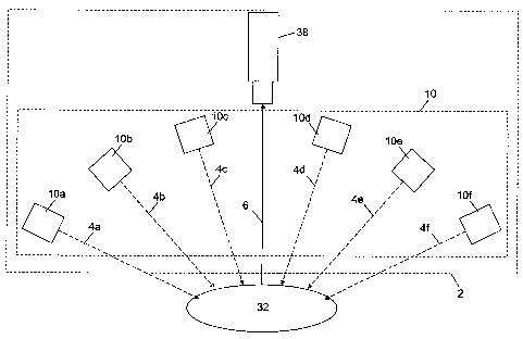
[0024] Shown in Fig. 1 is an imaging system 2 for illuminating an object 32,
such
as body tissue, with highly diffuse infrared light, and for producing a video
image of the object
32 based upon infrared light reflected from the object 32. As described in
detail herein, when
the object 32 is body tissue, blood vessels that are disposed below
subcutaneous fat in the
tissue may be clearly seen in the video image produced by the system 2.
[0025] The imaging system 2 includes an illumination system 10 that
illuminates
the object 32 with infrared light from multiple different illumination
directions. The system
10 includes multiple infrared light providers 10a-10f, each providing infrared
light to the object
32 from a different illumination direction. The directions of arrival of the
infrared light from
each light provider l0a-lOf are represented in Fig. 1 by the rays 4a-4f. As
shown in Fig. 1,
the directions of arrival of the infrared light ranges from perpendicular or
near perpendicular
to the surface of the object 32, to parallel or near parallel to the surface
of the object 32.
Since the infrared illumination arrives at the object 32 from such a wide
range of
illumination directions, the infrared illumination is highly diffuse.
[0026] As described in greater detail hereinafter, the light providers l0a-lOf
are
preferably light reflecting surfaces that direct light from a single light
source toward the
object 32. In other embodiments, the light providers l0a-lOf are individual
light sources, or
combinations of light sources and reflectors.
[0027] The imaging system 2 also includes an imaging device 38, such as a
video
camera, for viewing the object 32. The imaging device 38 views the object 32
from a viewing
direction which is represented in Fig. 1 by the arrow 6. The imaging device 38
receives the
diffuse infrared light reflected from the object 32, and generates an
electronic video image of
the object 32 based on the reflected infrared light.
[0028] Shown in Figs. 2a and 2b is a preferred embodiment of the illumination
system 10. Fig. 3 depicts a cross-sectional view of the system 10
corresponding to the section
A-A as shown in Figs. 2a-b. The system 10 preferably includes a light source
12 that emits
light into one end of a light diffusing structure 14. The light diffusing
structure 14 includes
an elongate outer enclosure 16 having reflective inner surfaces. Preferably,
the inner surfaces
of the elongate outer enclosure 16 are white in color. Alternatively, these
reflective surfaces
4
CA 02518315 2006-04-06
are mirrored surfaces, or a combination of white and mirrored surfaces. At the
end of the light
diffusing structure 14 opposite the light source 12, is a hollow light guide
22. As described in
more detail below, the light guide 22 serves as an output aperture for the
diffuse light.
[0029] The elongate outer enclosure 16 includes first and second sections 16a
and 16b, each having a large end and small end. Preferably, the first and
second sections
16a and 16b are substantially pyramidal in shape, each having four trapezoidal
faces. In the
preferred embodiment, the four trapezoidal faces of the sections 16a and 16b
are identical,
such that each end of the sections 16a and 16b forms a square aperture. As
shown in Figs. 2a
and 2b, the larger ends of the first and second sections 16a and 16b are
joined together to form
enclosure 16.
[0030] At the small end of the first section 16a is an input aperture 18
formed by
the four short sides of the four trapezoidal faces of the section 16a. The
light source 12 is
preferably attached to the small end of the first section 16a at the input
aperture 18. Thus, the
light generated by the light source 12 enters the elongate enclosure 16 at the
input aperture
18, and illuminates the interior surfaces of the enclosure 16.
[0031] At the small end of the second section 16b is an output aperture 20
formed
by the four short sides of the four trapezoidal faces of the section 16b.
Attached at the output
aperture 20 is one end of the hollow light guide 22. The light guide 22
preferably has white
reflective inner surfaces similar to the inner surfaces of the enclosure 16.
[0032] The system 10 also includes an elongate inner reflector 24 which is
disposed within and preferably coaxial with the outer enclosure 16. For
clarity, the inner
reflector 24 is shown in Fig. 2b removed from the outer enclosure 16. In the
preferred
embodiment, the inner reflector 24 is formed from a square tubular section 24a
joined to the
square base of a pyramidal section 24b. Preferably, the pyramidal section 24b
has four sides
that taper down to an apex. As shown in Fig. 3, the apex of the pyramidal
section 24b is
disposed proximate the input aperture 18 of the outer enclosure 16. The inner
reflector 24 has
reflective white outer surfaces similar to those of the inner surfaces of the
outer enclosure 16.
[0033] The light diffusing characteristics of the structure 14 are best
understood
with reference to Fig. 3. Within the light source 12 is a lamp 26, such as a
quartz-halogen
bulb and gold-plated reflector manufactured by Gilway and having part number
L517A-G.
When energized, the lamp 26 produces electromagnetic radiation in the form of
white light.
5
CA 02518315 2006-04-06
[0034] For purposes of this description, the lamp 26 may be thought of as a
point source radiating light in multiple directions, as represented by the
exemplary rays 28 and
30. As shown in Fig. 3, the ray 28 reflects from the inner surface of the
section 16b of the
outer enclosure 16. The ray 28 then travels through the output aperture 20,
into the light guide
22, and, after multiple reflections from the inner surfaces of the light guide
22, emits from the
exit aperture 23. The ray 30, which exits the light source 12 from a different
angle than the
ray 28, reflects from the inner reflector 24. The ray 30 then reflects from
the inner surface of
the section 16b of the outer enclosure 16, and travels through the output
aperture 20 and into
the light guide 22. After multiple reflections from the inner surfaces of the
light guide 22, the
ray 30 also emits from the exit aperture 23, but at a different angle than
that of the ray 28.
[0035] When an object 32 is placed near the exit aperture 23, the rays 28 and
30
arrive at the object 32 from different angles. It will be appreciated that the
light radiating from
the light source 12 could be represented as an infinite number of rays which
strike and reflect
from the inner reflector 24 and the inner surfaces of the outer enclosure 16
from an infinite
number of angles. Thus, the light emitted from the exit aperture 23 arrives at
the object 32
from many different angles, and is therefore highly diffuse light. These
arrival angles range
from near perpendicular to near parallel with the plane of the exit aperture
23. Since the
diffusing structure 14 is three-dimensional, it will be appreciated that light
also reflects from
the other surfaces of the outer enclosure 16 and the inner reflector 24, such
as those that are
perpendicular to the surfaces shown in Fig. 3. Therefore, the light emitted at
the exit aperture
23 of the illumination system 10 is highly diffuse, appearing to be generated
by many
different light sources.
[0036] Due to the arrangement of the reflective inner surfaces of the outer
enclosure 16 and the reflective outer surfaces of the inner reflector 24, the
diffusing structure
14 efficiently transfers the light radiated from the lamp 26 to the exit
aperture 23. Thus, a
very large fraction of the light provided by the lamp 26 reaches the object
32, and very little
light energy is wasted.
[0037] As described in more detail below, the illumination system 10 can be
used
to provide diffuse light for medical imaging purposes. However, it will be
appreciated that
the scope of the invention is not limited to medical uses. The system 10 could
also be used as
a diffuse light source for general photographic purposes.
6
CA 02518315 2006-04-06
[0038] In a preferred embodiment of the invention, as depicted in Fig. 3, the
light
source 12 includes a cold mirror 34 disposed between the lamp 26 and the input
aperture 18
of the outer enclosure 16. The cold mirror 34 reflects substantially all light
having
wavelengths outside a selected infrared range of wavelengths. Preferably, the
selected range
includes wavelengths from approximately 700 to 1000 nanometers. Immediately
proximate
the cold mirror 34, and disposed between the cold mirror 34 and the input
aperture 18, is an
infrared transmitting filter 36 which further attenuates light having
wavelengths outside the
selected infrared range while transmitting light having wavelengths within the
selected
infrared range. Thus, the light that passes through the cold mirror 34 and the
filter 36 into the
outer enclosure 16 is infrared light having wavelengths within the selected
infrared range.
[0039] It should be appreciated that there are other ways that the light
source 12
could be configured to generate infrared light. For example, the light source
12 could consist
of an infrared light-emitting diode (LED) or an array of infrared LED's. Thus,
the
configuration of the light source 12 shown in Fig. 3 and described above is a
preferred
embodiment only, and the invention is not limited to any particular
configuration of the light
source 12.
[0040] Fig. 4 depicts the dimensions of a preferred embodiment of the
illumination system 10. As shown in Fig. 4, the total length of the light
diffusing structure 14
is approximately 34.82 inches. The height and width of the outer enclosure 16
at the
juncture of the first and second sections 16a and 16b is approximately 10.04
inches. The
preferred length of the light guide 22 is approximately 14.00 inches, and its
height and width is
approximately 5.08 inches. Preferably, the total length of the inner reflector
24 is
approximately 15.86 inches. The preferred length of the tubular section 24a of
the inner
reflector 24 is approximately 7.93 inches. The height and width of the tubular
section 24a is
approximately 3.5 inches. The height and width of the light source 12 is
approximately 2.11
inches.
[0041] As shown in Fig. 4, a preferred embodiment of the invention includes a
lens
40 used in conjunction with the video imaging device 38 to produce a video
image of the object
32 based on diffuse light reflected from the object 32. Preferably, the
imaging device 38 of
this embodiment is a charge-coupled device (CCD) video camera 38 manufactured
by Cohu,
having model number 631520010000. The lens 40 of the preferred embodiment is a
25 mm f-
0.95 movie camera lens manufactured by Angenieux.
7
CA 02518315 2006-04-06
[0042] The camera 38 and lens 40 of the preferred embodiment are disposed
within the tubular section 24a of the inner reflector 24. As shown in Fig. 4,
the open end of the
tubular section 24a forms an aperture toward which the camera 38 and lens 40
are pointed. In
this manner, the hollow light guide 22 is substantially centered within the
field of view of the
camera 38. Thus, the camera 38 receives light reflected from the object 32
that enters the light
guide 22, travels through the enclosure 16, and enters the open end of the
section 24a.
[0043] As shown in Fig. 4, the preferred embodiment of the invention includes
an
infrared-transmitting filter 42 disposed in the open end of the tubular
section 24a. This filter 42
receives light reflected from the object 32, and any other light that may
enter the enclosure
16, and substantially eliminates all light having wavelengths outside the
infrared range of
approximately 700 to 1000 nanometers. In the preferred embodiment, the filter
42 substantially
eliminates light having wavelengths outside a selected infrared range of
approximately 800 to
850 nanometers. Thus, the light that passes through the filter 42 and into the
lens 40 is
infrared light within the selected wavelength range. Therefore, the camera 38
primarily
receives infrared light which originates from within the illumination system
10 and which is
reflected from the object 32.
[0044] Based on the light reflected from the object 32, the camera 38
generates a
video image of the object 32 in the form of an electrical video signal. As
shown in Fig. 5, the
video signal is preferably provided to an image enhancement board 44, such as
a board
manufactured by DigiVision having a model number ICE-3000. The board 44
generates an
enhanced video image signal based on the video signal from the camera 38. The
enhanced
video image signal is provided to a video capture and display card 46, such as
a model 20-TD
Live card manufactured by Miro. The card 46 captures still images from the
image signal
which may be saved in digital format on a digital storage device. The card 46
also formats the
video image signal for real-time display on a video monitor 48.
[0045] It should be appreciated that the illumination system 10 could use
other
means for generating diffuse infrared light in accordance with the invention.
For example, the
light providers l0a-lOf of Fig. 1 could be embodied by a ring-light strobe
light. Alternatively,
a circular array of LED's could be used to illuminate a plastic transmitting
diffuser placed near
the surface of the object 32. In the latter embodiment, the light providers
l0a-lOf would
correspond to the individual LED's in the array.
8
CA 02518315 2007-07-17
[0046] In an alternative embodiment of the invention depicted in Figs. 6a and
6b,
the imaging system 2 includes a video projector 50 for illuminating the object
32 with an
image of the object 32 to enhance the visual contrast between lighter and
darker areas of the
object 32. As described in U.S. patent number 5,969,754 entitled CONTRAST
ENHANCING
ILLUMINATOR, the features of an object are visually enhanced for an observer
when the
features of a projected visible-light image of the object overlay the
corresponding features of
the object. The overlaid visible-light image causes the bright features of the
object to appear
brighter while the dark areas remain the same.
[0047] The embodiment of the invention shown in Figs. 6a and 6b provides
diffuse infrared light (represented by the rays 52) to the object 32 in a
manner similar to that
described previously. However, in the embodiment shown in Figs. 6a and 6b, the
optical path
of the illuminating light is folded, such that the exit aperture 23 of the
light guide 22 is
rotated by 90 degrees relative to the exit aperture shown in Figs. 1-3.
[0048] As shown in Fig. 6b, a beam separator, such as a hot mirror 54,
receives
infrared light 52 from the interior of the light diffusing structure 14 and
reflects the infrared
light 52 into the light guide 22 and toward the object 32. The hot mirror 54
also receives an
infrared image of the object 32 (represented by the ray 56) and reflects it
toward the camera 38.
The hot mirror 54 receives the visible-light image (represented by the ray 58)
from the
projector 50 and transmits it into the light guide 22 and toward the object
32.
[0049] As explained in greater detail in U.S. patent number 5,969,754, the
video output signal from the video camera 38 is provided as a video input
signal to the
projector 50. Based on the video input signal, the projector 50 projects the
visible-light image
58 of the object 32 toward the hot mirror 54. The hot mirror 54 receives the
visible-light
image 58 and transmits it into the light guide 22 toward the object 32. By
proper alignment of
the projected visible-light image 58 from the projector 50 with the infrared
image 56 of the
object 32 which is sensed by the camera 38, the features in the projected
visible-light image
58 are made to overlay the corresponding features of the object 32.
[0050] When the object 32 is body tissue, and the invention is used to find
subcutaneous blood vessels in the body tissue, the blood vessels appear as
dark lines in the
projected visible-light image 58. Thus, when the visible-light image 58 is
projected onto the
body tissue, the subcutaneous blood vessels will lie directly beneath the dark
lines in the
9
CA 02518315 2006-04-06
projected visible-light image 58. In this manner, the invention significantly
improves a
medical practitioner's ability to find subcutaneous blood vessels while
minimizing discomfort
for the patient.
100511 Figs. 7a and 7b depict an alternative embodiment of the invention for
use
as a contrast enhancing illuminator. The embodiment of Figs. 7a-b operates in
a fashion
similar to the embodiment of Figs. 6a and 6b. However, in the embodiment of
Figs. 7a-b, the
camera 38 is located outside the light diffusing structure 14. To accommodate
the different
location of the camera 38, the hot mirror 54 shown in Figs. 7a-b is rotated by
90 degrees
clockwise relative to its position in Figs. 6a-b. Otherwise, the hot mirror 54
serves a similar
function as that described above in reference to Figs. 6a-b. Also to
accommodate the different
camera location, the infrared-transmitting filter 42 is mounted in a wall of
the light guide 22.
A reflective panel 60 is provided in this embodiment to further direct the
light from the light
source 12 into the light guide 22 and toward the exit aperture 23. Preferably,
the panel 60 is a
flat reflective sheet having an orifice therein to allow light to pass between
the object 32 and
the camera 38 and projector 50.
[0052] A preferred embodiment of a relatively compact and highly reliable
imaging system 70 is depicted in Figs. 8-11. The imaging system 70 is most
preferably
configured to illuminate an object 71, such as body tissue and the like, and
to produce a video
image of the object 71 based upon infrared light reflected from the object 71.
The imaging
system 70 preferably includes a housing 72 which contains the imaging features
of the system
70.
[0053] As shown in Fig. 8, the housing 72 preferably has a substantially
rectangular configuration. The housing 72 preferably has a length of between
about three and
about five inches and a width of about three and one-half inches. It will be
appreciated by
those skilled in the art that the imaging system 70 can be configured in a
variety of ways and
the invention should not be limited by any specific examples or embodiments
discussed
herein. For example, in Fig. 8 the housing is depicted as being substantially
rectangular,
however, circular, polygonal, and other geometries and sizes are feasible as
well.
100541 An imaging device 74, such as a video camera having a lens 75, and
video
processing components reside within the housing 72. The imaging device 74 and
video
processing components operate to detect infrared light and to process the
detected infrared light
from the object 71. The imaging system 74 produces an image based on the
detected infrared
CA 02518315 2006-04-06
light reflected from the object 71, as described herein. As shown in Figs. 8
and 9, the imaging
device 74 is preferably mounted within an aperture 76 of mounting wall 78,
with the lens 75
extending into the housing interior 77, as described further below. More
particularly, the
camera 74 is preferably centrally and symmetrically mounted within the housing
72. This
preferred symmetrical camera location tends to maximize the amount of light
detected by the
camera, which enhances the image produced by the system 70, thereby enhancing
the
illumination of blood vessels disposed below subcutaneous fat in body tissue.
[0055] The housing 72 most preferably contains various components operable to
transmit diffuse light from the system 70 toward the object 71. Arrows 80
represent diffuse
light transmitted by the system 70. Arrows 82 represent the light reflected
from the object 71.
As shown in Fig. 9, as viewed in the direction of the arrows along the section
line A-A of Fig.
8, the wall 78 contains a number of infrared light emitting diodes (LEDs) 84
disposed in a
LED array 85 for emitting infrared light. The LED array 85 defines a LED plane
of reference.
When activated, each LED 84 preferably transmits light at a wavelength of
about 740
nanometers (nm). In the preferred embodiment, each LED 84 is manufactured by
Roithner
Lasertechnik of Austria under model number ELD-740-524.
[0056] As shown in Fig. 10, and according to the preferred embodiment, the
LEDs 84 are mounted on a circuit board 86 located adjacent to wall 78. As
shown in Fig. 9,
there are most preferably eight groups 92, 94 of LEDs 84 concentrically
arranged about the
imaging system 74. The concentric LED arrangement tends to provide maximal
dispersion
and transmission of diffuse light from the system 70. It is preferred that
each group 92, 94 of
LEDs 84 contain at least ten LEDs 84. However, the system 70 can include more
or fewer
LEDs within a particular group depending upon a desired implementation of the
system 70.
Furthermore, the system 70 can include more or fewer groups of LEDs in the LED
array 85.
100571 With continuing reference to Fig. 9, there are four groups 92 of LEDs
84
located about the corner regions 96 of the LED array 85. Most preferably, at
least fifteen
LEDs 84 are disposed in each corner region 96 of the LED array 85. There are
preferably
four groups 94 of LEDs 84 disposed in lateral regions 98 of the LED array 85.
Each lateral
region 98 is located substantially between each corner region 94. Most
preferably, at least ten
LEDs 84 are disposed in each lateral region 98 of the LED array 85.
[0058] As described above, the LED array is most preferably disposed on
circuit board 86. In conjunction with the control system 90, the circuit board
86 includes
11
CA 02518315 2006-04-06
control circuitry that controls the activation of one or more LEDs 84 within a
particular group
or groups 92, 94 of LEDs 84 in the LED array 85. As shown in the block diagram
of Fig. 11,
a power source 88 and a control system 90, such as a microprocessor or similar
control
device, are electrically connected to the circuit board 86. It will be
appreciated that it is also
possible to control the LEDs without using a control system 90, that is, power
source 88 can
be switched "on" or "off' to activate and deactivate the LED array 85. It will
be appreciated
that pulse modulation techniques can also be used in conjunction with power
source 88 to
activate and deactivate one or more of the LEDs 84 in the LED array 85
according to a
preferred duty cycle, herein defined as the LED "on" time relative to the LED
"off' time.
[0059] As shown in the block diagram of Fig. 11, in a preferred embodiment of
the imaging system 70, the LED array 85 is electrically connected via circuit
board 86 to the
power source 88 and control system 90. The control system 90 includes control
features for
controlling the LED array 85 to emit infrared light toward an object 71. As
described herein,
the control system 90 can enable one or more of the LEDs 84 in a group or
groups of the
LED array 85 to emit light continuously or intermittently. That is, one LED 84
or a plurality
of LEDs 84 can be selected and controlled to emit infrared light
intermittently or continuously
toward the object 71. Thus, the system 70 can be configured to transmit
infrared light from
the LED array in various permutations and combinations of LEDs 84 and/or LED
groups 92,
94.
[0060] Referring now to Fig. 10, a first diffusion layer 100 is disposed
adjacent to
the emitting surfaces 102 of the LEDs 84 in the LED array 85. According to a
preferred
embodiment, the first diffusion layer 100 is glued, such as using known
adhesives onto the
emitting surfaces 102 of the LED array 85, thereby operating to diffuse the
light emitted by
one or more LEDs 84 in the LED array 85. The first diffusion layer 100 is most
preferably a
holographic twenty degree diffuser, such as a product having identification
code LSD20PC10-
FlOx10/PSA, manufactured by Physical Optics Corporation of Torrance,
California. Most
preferably, the first diffusion layer 100 has a length.of about three and one-
half inches, a
width of about three and one-half inches, and a thickness of about 0.10
inches. When one or
more of the LEDs 84 in the LED array 85 are activated, the first diffusion
layer 100 diffuses the
infrared light emitted from the LED array 85, thereby providing a first amount
of diffusion to
the emitted infrared light.
12
CA 02518315 2006-04-06
[0061] The interior surfaces 104 of the housing 72 are shown in Fig. 10. Most
preferably, the interior surfaces 104 are coated with a reflective coating,
such as white paint
or the like, which reflects and further diffuses the already diffuse light
produced by the first
diffusion layer 100. With continuing reference to Fig. 10, a second diffusion
layer 106 is
spaced apart from the first diffusion layer 100 by a distance LDD. Most
preferably, the
distance LDD between the first and second diffusion layers 100 and 106 is
about three inches.
The second diffusion layer 106 is most preferably a holographic twenty degree
diffuser,
similar to or the same as the above-described first diffusion layer 100. The
second diffusion
layer 106 has a preferred length of about three and one-half inches, a width
of about three and
one-half inches, and a thickness of about 0.10 inches.
[0062] The second diffusion layer 106 further diffuses the already diffuse
light
reflected from the interior surfaces 104 and provided by the first diffusion
layer 100. As
shown in Fig. 8, the first and second diffusion layers are substantially
planar, that is, the layers
100 and 106 each define a planar geometry. According to the most preferred
embodiment, the
planes defined by the first and second diffusion layers 100 and 106 are
substantially parallel
with respect to one another. The preferred parallel planar arrangement of the
diffusion
layers 100, 106 tends to promote a quantifiable and uniform amount of diffuse
light
emanating from the system 70 when one or more of the LEDs 84 are enabled.
[0063] With continuing reference to Fig. 10, a backing material 108, such as
LUCITE, is disposed adjacent to the second diffusion layer 106. Most
preferably, the backing
material has a thickness of about 0.125 inches. A visible polarizer I 10 is
disposed adjacent to
the backing material 108. The visible polarizer 110 is most preferably
manufactured by
Visual Pursuits of Vernon Hills, Illinois under part number VP-GS-12U, and
having a
thickness of about 0.075 inches.
[0064] Thus, the system 70 is operable to produce various levels of diffusion
as
the emitted light progresses through the first diffusion layer 100, reflects
off of the interior
surfaces 104 of the first compartment 72a, and continues to progress through
the second
diffusion layer 106, backing material 108, and polarizer 110. Thus, a level of
diffusion results
after the emitted light passes through the first diffusion layer 100. Another
level of diffusion
results from the reflection from the interior surfaces 104 of the first
compartment 72a of the
already diffused light provided by the first diffusion layer 100. Yet another
level of diffusion
results after the diffuse light passes through the second diffusion layer 106.
13
CA 02518315 2006-04-06
[0065] As shown in Fig. 8, the visible polarizer 110 preferably includes a
central
portion 112, most preferably in the shape of a circle having about a one-inch
diameter. The
central portion 112 geometry most preferably coincides with the shape and
dimension of the
camera lens 75. The polarization of the central portion 112 is preferably
rotated
approximately ninety degrees with respect to the polarization of the
surrounding area 114 of
the polarizer 110. In the preferred embodiment, the camera lens 75 contacts
the backing
material 108. As shown in Fig. 8, the positional location of the lens 75
within the housing 70
preferably coincides with or shares the same central axis as the central
portion 112 of the
polarizer 110. The central portion 112 of the polarizer 110 coinciding with
the front of the
lens 75 tends to remove any surface glare in the resulting camera image.
[0066] As shown in Fig. 10, the backing material 108 and the visible polarizer
110 have planar surfaces which preferably include a similar planar orientation
with respect to
the planes defined by the first and second diffusion layers 100, 106.
According to a most
preferred embodiment, the first diffusion layer 100, interior surfaces 104,
second diffusion
layer 106, backing material 108, and visible polarizer 110 define a diffusing
system 116 (Fig.
10) for providing diffuse light to an object 71. It will be appreciated that
the diffusing
structure can include more or fewer components and the invention is not to be
limited by any
specific examples or embodiments disclosed herein. For example, the diffusing
system 116
can include either the first or the second diffusion layers 100, 106, with or
without the
polarizer 110, or can include the first and second diffusion layers 100, 106
without the
polarizer 110.
[0067] Once actuated, the system 70 operates to transmit diffuse light 80
toward
an object 71 and produce a video image of the object 71 with the imaging
system 74, as
described above. More particularly, once the power source 88 is enabled, one
or more of the
LEDs 84 in the LED array 85 emit infrared light from the emitting surface(s)
102. The first
diffusion layer 100 provides a first amount of diffusion to the emitted
infrared light. The
interior surfaces 104 further diffuse the diffuse light emanating from the
first diffusion layer
100. The second diffusion layer 106 further diffuses the already diffuse light
which is then
transmitted through the backing material 108 and the polarizer before
illuminating the object
71. As described above, the object 71 reflects the emitted diffuse light 80
producing diffuse
reflected light 82 that is captured by the imaging system 74. The imaging
system 74 then
produces a video image of the object 71. Accordingly, by emitting diffuse
light according to a
14
CA 02518315 2006-04-06
unique diffusion providing system 70, the system 70 aids in locating and
differentiating
between different material properties of the object 71, such as between blood
vessels and
tissue.
[0068] It is contemplated, and will be apparent to those skilled in the art
from the
preceding description and the accompanying drawings that modifications and/or
changes may
be made in the embodiments of the invention. For example, the planes defined
by the first
or second diffusing layers 100 and 106 can be adjusted to not be parallel with
respect to one
another, thereby providing different levels of diffuse light from the system
70. Furthermore, the
plane defined by the LED array 85 is most preferably in substantial parallel
relation with
respect to the plane defined by the first diffusing layer 100. However, the
planes defined by
LED array 85 and the first diffusing layer 100 can be varied to accommodate
various
operational conditions, as will be appreciated by those skilled in the art.
Accordingly, it is
expressly intended that the foregoing description and the accompanying
drawings are
illustrative of preferred embodiments only, not limiting thereto, and that the
true spirit and
scope of the present invention be determined by reference to the appended
claims.