Language selection

Search

Patent 2518325 Summary

Third-party information liability

Some of the information on this Web page has been provided by external sources. The Government of Canada is not responsible for the accuracy, reliability or currency of the information supplied by external sources. Users wishing to rely upon this information should consult directly with the source of the information. Content provided by external sources is not subject to official languages, privacy and accessibility requirements.

Claims and Abstract availability

Any discrepancies in the text and image of the Claims and Abstract are due to differing posting times. Text of the Claims and Abstract are posted:

  • At the time the application is open to public inspection;
  • At the time of issue of the patent (grant).
(12) Patent: (11) CA 2518325
(54) English Title: APPARATUS FOR FORMING WASTE CONTAINING PACKS
(54) French Title: DISPOSITIF DE FORMATION DE PAQUETS A DECHETS
Status: Deemed expired
Bibliographic Data
(51) International Patent Classification (IPC):
  • B65F 1/06 (2006.01)
  • B65F 1/14 (2006.01)
  • B65B 9/12 (2006.01)
(72) Inventors :
  • MORAND, MICHEL (Canada)
(73) Owners :
  • LES DEVELOPPEMENTS ANGELCARE INC. (Canada)
(71) Applicants :
  • LES DEVELOPPEMENTS ANGELCARE INC. (Canada)
(74) Agent: NORTON ROSE FULBRIGHT CANADA LLP/S.E.N.C.R.L., S.R.L.
(74) Associate agent:
(45) Issued: 2013-01-22
(22) Filed Date: 2005-09-07
(41) Open to Public Inspection: 2007-03-07
Examination requested: 2009-09-22
Availability of licence: N/A
(25) Language of filing: English

Patent Cooperation Treaty (PCT): No

(30) Application Priority Data: None

Abstracts

English Abstract

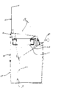
An apparatus for forming waste containing packs from a length of flexible tubing is formed of a housing having a top portion, an intermediate portion and a lower portion. The top portion displays an opening to receive waste material therein and a cassette containing a package of a flexible pleated tubing. The intermediate portion has a retractable guillotine-type member sealingly contacting the tubing dispensed from the cassette and extending downwardly into the lower portion of the housing. Retraction of the member causes waste material received in the tubing of the upper and intermediate portions of the housing to be dispensed in a closed end tubing in the lower portion of the housing.


French Abstract

Un appareil pour former des paquets contenant des déchets à partir d'une longueur de tube flexible comprend un boîtier ayant une partie supérieure, une partie intermédiaire et une partie inférieure. La partie supérieure affiche une ouverture pour recevoir des déchets dans celle-ci et une cassette contenant un emballage d'un tube plissé flexible. La partie intermédiaire a un élément de type guillotine rétractable en contact de manière étanche avec le tube distribué à partir de la cassette et s'étendant vers le bas dans la partie inférieure du boîtier. La rétraction de l'élément amène les déchets reçus dans le tube des parties supérieure et intermédiaire du boîtier à être distribués dans un tube d'extrémité fermée dans la partie inférieure du boîtier.

Claims

Note: Claims are shown in the official language in which they were submitted.


-6-
CLAIMS

1. An apparatus for forming waste containing packs from a length of flexible
tubing comprising:
a housing including a bottom portion, an intermediate portion and a top
portion; said top portion having an opening to receive waste material
therethrough;
a cassette mounted in said top portion and containing a package of tubing
in a flexible pleated condition; said cassette being so constructed as to
enable
the tubing to be dispensed therefrom and downwardly into said intermediate and
lower portions of said housing; said tubing in said bottom portion having a
closed
end;
a sliding member mounted in said intermediate portion of the housing and
movable between an inward tubing engaging position and an outward retracted
position; said member having an outer end extending outside said housing and
an inner end extending in said intermediate portion of said housing to
contactingly squeeze said tubing thereby forming a lower waste receiving
tubing
compartment and an upper waste receiving tubing compartment; whereby waste
material received through said opening and in said upper compartment is
dispensed, upon retraction of said member, into said lower compartment and
whereby, when said inner end of said member is in said tubing squeezing
position, the waste material in said lower compartment is sealingly enclosed
therein; and
a lock on the sliding member for locking said sliding member in said tubing
squeezing position, the lock lockingly engaging the housing solely when the
sliding member reaches the tubing squeezing position; said lock being
disengageable for retraction of said member from said intermediate portion of
the
housing.

2. An apparatus as defined in claim 1, wherein said outer end of said
member defines a handle.


-7-
3. An apparatus as defined in claim 1, wherein said lower portion of said
housing is hingedly connected to said intermediate portion to provide access
to
contents in said lower portion of said housing.

4. An apparatus as defined in claim 1, further comprising a cover hingedly
connected to said top portion of the housing.

5. An apparatus as defined in claim 1, wherein said intermediate portion
includes a back plate cooperating with said member to define said tubing
squeezing position.

6. An apparatus as defined in claim 1, further comprising cutter means in
said housing allowing said lower compartment of said tubing to be severed from
said upper compartment.

7. An apparatus as defined in claim 1, wherein said closed end consists in a
knot formed at an open end of said tubing.

8. An apparatus as defined in claim 1, wherein the lock is a protuberance on
the sliding member releasably engaging the housing.

9. An apparatus as defined in claim 8, wherein the lock further comprises a
finger being manually depressed to release the protuberance from the housing.
10. An apparatus as defined in claim 1, wherein the sliding member is inclined
in the housing with respect to the horizontal.

Description

Note: Descriptions are shown in the official language in which they were submitted.


CA 02518325 2005-09-07
-1-
TITLE OF THE INVENTION
Apparatus for forming waste containing packs
FIELD OF THE INVENTION
The present invention relates to an apparatus for forming waste containing
packs
from a length of flexible tubing.
BACKGROUND OF T:iE INVENTION
It is known, for the disposal of waste material, to use packs of flexible
tubing
wherein waste material is packaged in individual packs along a length of such
flexible tubing. One example of such apparatus using packs of flexible tubing
for
the ready disposal of babies' disposable nappies may be found described in US
Patent number 4,869,049 issued September 26, 1989 to Richards et al. In this
patent, a core is used and turned to twist the flexible material at locations
between adjacent waste containing packs to seal the packs at their ends
thereby
providing hygienic disposal of the waste material. The packages are collected
in
a bin portion of the apparatus and when it is desired to remove the packages
from the bin portion, the bottom of the apparatus is opened to discharge the
packages to a waste disposal facility. A similar apparatus may also be found
described in Canadian patent application No. 2,372,143 published August 15,
2003.
OBJECTS AND STATEMENT OF THE INVENTION
It is an object of the present invention to provide an improved apparatus for
forming waste containing packs from a length of flexible tubing.
The apparatus comprises:
a housing including a bottom portion, an intermediate portion and a top
portion; the top portion displaying an opening to receive waste material
therethrough;


CA 02518325 2005-09-07
-2-
a cassette mounted in the top portion and containing a package of flexible
pleated tubing; the cassette being so constructed as to enable tubing to be
dispensed therefrom and downwardly into the intermediate and lower portions of
the housing; the tubing in the bottom portion having a closed end; and
a guillotine-type member mounted in the intermediate portion of the housing
and
movable between an inward tubing engaging position and an outward retracted
position; the member having an outer end extending outside the housing and an
inner end extending in the intermediate portion of the housing to contactingly
squeeze the tubing thereby forming a lower waste receiving tubing compartment
and an upper waste receiving tubing compartment; whereby waste material
received through the opening and in the upper compartment is dispensed, upon
retraction of the member, into the tower compartment and whereby, when the
inner end of the member is in the tubing squeezing position, the waste
material in
the lower compartment is sealingly enclosed therein.
In one form of the invention, the housing has a cutter for separating a waste
containing pack from the tubing.
Other objects and further scope of applicability of the present invention will
become apparent from the detailed description given hereinafter. It should be
understood, however, that this detailed description, while indicating
preferred
embodiments of the invention, is given by way of illustration only, since
various
changes and modifications within the spirit and scope of the invention will
become apparent to those skilled in the art.
IN THE DRAWINGS:
Figure 1 is a perspec.ive view showing one side of an apparatus for forming
waste containing packs made in accordance with the present invention;
Figure 2 is a perspective view showing another side of the apparatus;


CA 02518325 2005-09-07
-3-
Figure 3 is an elevational cross-sectional view showing the apparatus without
waste material therein;
Figure 4 is a cross-sectional view similar to figure 3, but showing waste
material
being dropped in the top portion of the housing;
15
Figures 5 and 6 are cross-sectional views showing two positions of the
retracting
guillotine-type member; and
Figure 7 is a cross-sectional view showing waste material sealingly enclosed
in
the lower portion of the housing.
DESCRIPTION OF PREFERRED EMBODIMENTS
Referring to figures 1, 2 and 3, there is shown an apparatus, generally
denoted
10, for forming waste containing packs in accordance with the present
invention.
The apparatus comprises an enclosed housing formed of a top portion 12 having
a cover 14, an intermediate portion 16 and a bottom portion 18. Cover 14 is
hingedly connected to the top portion 12 at edge 20.
Top portion 12 has a funnel shaped opening 22 and is provided with a base area
24 to support a cassette 26 containing a package of flexible pleated tubing
28.
Such cassette may be found described in applicant's Canadian patent
application
no. 2,366,384 published August 15, 2003.
The intermediate portion 16 is constructed to receive a guillotine-type
sliding
member 30 having an inner end 30a extending inside the intermediate portion
and an outer side 30b extending outside the housing and defining the shape of
a
handle. Member has a smooth top surface 30C. The intermediate portion 16
also includes an inclined back plate 32 the function of which will be
described
further hereinbelow. Mounted to the rear wall of plate 32, is a cutter 36, the
function of which will be also described below. The intermediate portion 16 is


CA 02518325 2005-09-07
-4-
hingedly connected at edge 38 to the bottom portion 18 to provide access to
contents inside the bottom portion 18.
A locking arrangement in the form of a clamp finger 40 is provided on member
30
to secure the latter to the intermediate portion 16 and to facilitate the
displacement of the apparatus by a user. By depressing finger 40, the
protuberance 42 will free the adjacent wall of the intermediate portion of the
housing, thus allowing full retraction of the sliding member.
For the operation of the apparatus of the present invention, a length of
tubing is
first drawn through the center portion of the cassette and a knot 58 is made
to
form a closed end. The length of tubing should be at least sufficient to
contact
and lie on the bottom wall of the bottom portion of the housing. The cassette
is
placed in the top portion of the apparatus and the housing is hingedly closed.
The member 30 is slid into the intermediate portion until the end 30a
contactingly
squeezes the tubing against the back plate 32 thereby forming in the tubing
inside the housing an upper compartment 44 and a lower compartment 46.
Referring to figure 4, the cover 14 is lifted so that waste material 48 may be
deposited through the funnel shape opening 22 of the top portion into the
upper
compartment 44 of the tubing. Cover 14 is then closed. The clamp finger 40 is
depressed in the direction indicated by arrow 50 so that the protuberance 42
may
free the edge 43 of the wall of the intermediate portion. As the sliding
member 30
is retracted in the direction indicated by arrow 52, the waste material 48
drops in
the lower compartment 46 of the tubing (see figure 6).
Thereafter, the sliding member is reinserted in the direction opposite to the
direction 52 to again have its end 30a squeeze the tubing against the back
plate
32 of the intermediate portion. This contact ensures that odours of the waste
material 48 is sealingly enclosed in the lower compartment 46 of the tubing.
When it is wished to remove the packed content of the bottom portion, button
60
forming part of the front wall of the lower portion 18 is inwardly depressed
so that


CA 02518325 2005-09-07
-5-
the intermediate portion with the top portion and its cover the edge 38. The
user
uses cutter 36 to sever the lower compartment 46 from the rest of the tubing.
A
pair of notches is made, one (not shown) for the severed end of the pack
containing the waste material, the other (similar to knot 58) for the severed
free
open of the length of tubing extending from the cassette to form another waste
material receiving compartment in the lower portion of the housing.
Although the invention has been described above'n relation to one specific
form,
it will be evident to a person skilled in the art that it may be refined and
varied.
For example, a scoop holder may be attached to or molded directly to the
housing. Also, the bottom portion can be made part of a cat liter box. It is
therefore wished to have it understood that the present invention should not
be
limited in interpretation except by the terms of the following claims.

Representative Drawing
A single figure which represents the drawing illustrating the invention.
Administrative Status

For a clearer understanding of the status of the application/patent presented on this page, the site Disclaimer , as well as the definitions for Patent , Administrative Status , Maintenance Fee  and Payment History  should be consulted.

Administrative Status

Title Date
Forecasted Issue Date 2013-01-22
(22) Filed 2005-09-07
(41) Open to Public Inspection 2007-03-07
Examination Requested 2009-09-22
(45) Issued 2013-01-22
Deemed Expired 2017-09-07

Abandonment History

There is no abandonment history.

Payment History

Fee Type Anniversary Year Due Date Amount Paid Paid Date
Application Fee $400.00 2005-09-07
Registration of a document - section 124 $100.00 2006-12-08
Maintenance Fee - Application - New Act 2 2007-09-07 $100.00 2007-08-31
Maintenance Fee - Application - New Act 3 2008-09-08 $100.00 2008-09-05
Maintenance Fee - Application - New Act 4 2009-09-08 $100.00 2009-09-08
Request for Examination $800.00 2009-09-22
Maintenance Fee - Application - New Act 5 2010-09-07 $200.00 2010-07-19
Maintenance Fee - Application - New Act 6 2011-09-07 $200.00 2011-06-13
Maintenance Fee - Application - New Act 7 2012-09-07 $200.00 2012-06-11
Final Fee $300.00 2012-11-06
Maintenance Fee - Patent - New Act 8 2013-09-09 $200.00 2013-06-14
Maintenance Fee - Patent - New Act 9 2014-09-08 $200.00 2014-08-04
Maintenance Fee - Patent - New Act 10 2015-09-08 $250.00 2015-06-11
Owners on Record

Note: Records showing the ownership history in alphabetical order.

Current Owners on Record
LES DEVELOPPEMENTS ANGELCARE INC.
Past Owners on Record
MORAND, MICHEL
Past Owners that do not appear in the "Owners on Record" listing will appear in other documentation within the application.
Documents

To view selected files, please enter reCAPTCHA code :


To view images, click a link in the Document Description column. To download the documents, select one or more checkboxes in the first column and then click the "Download Selected in PDF format (Zip Archive)" or the "Download Selected as Single PDF" button.

List of published and non-published patent-specific documents on the CPD .

If you have any difficulty accessing content, you can call the Client Service Centre at 1-866-997-1936 or send them an e-mail at CIPO Client Service Centre.


Document
Description 
Date
(yyyy-mm-dd) 
Number of pages   Size of Image (KB) 
Abstract 2005-09-07 1 18
Description 2005-09-07 5 190
Claims 2005-09-07 2 59
Drawings 2005-09-07 7 164
Representative Drawing 2007-02-14 1 10
Cover Page 2007-02-27 2 43
Claims 2012-02-03 2 70
Cover Page 2013-01-07 2 44
Assignment 2005-09-07 3 85
Correspondence 2005-10-21 1 27
Prosecution-Amendment 2009-09-22 2 65
Assignment 2006-12-08 2 62
Fees 2007-08-31 1 46
Fees 2008-09-05 1 45
Prosecution-Amendment 2011-08-04 2 86
Prosecution-Amendment 2009-09-08 2 59
Correspondence 2009-09-30 1 13
Correspondence 2009-09-30 1 20
Correspondence 2012-11-06 2 66
Prosecution-Amendment 2012-02-03 4 184