Language selection

Search

Patent 2519245 Summary

Third-party information liability

Some of the information on this Web page has been provided by external sources. The Government of Canada is not responsible for the accuracy, reliability or currency of the information supplied by external sources. Users wishing to rely upon this information should consult directly with the source of the information. Content provided by external sources is not subject to official languages, privacy and accessibility requirements.

Claims and Abstract availability

Any discrepancies in the text and image of the Claims and Abstract are due to differing posting times. Text of the Claims and Abstract are posted:

  • At the time the application is open to public inspection;
  • At the time of issue of the patent (grant).
(12) Patent: (11) CA 2519245
(54) English Title: SYSTEM AND METHOD FOR PRINTING A CODE ON AN ELONGATE ARTICLE AND THE CODE SO PRINTED
(54) French Title: SYSTEME ET PROCEDE POUR IMPRIMER UN CODE SUR UN ARTICLE ALLONGE ET CODE AINSI IMPRIME
Status: Expired and beyond the Period of Reversal
Bibliographic Data
(51) International Patent Classification (IPC):
  • B41J 3/28 (2006.01)
  • B41J 3/01 (2006.01)
  • B41J 3/407 (2006.01)
(72) Inventors :
  • LESSARD, ROBERT (Canada)
(73) Owners :
  • AUTOLOG INC.
(71) Applicants :
  • AUTOLOG INC. (Canada)
(74) Agent: ROBIC AGENCE PI S.E.C./ROBIC IP AGENCY LP
(74) Associate agent:
(45) Issued: 2008-11-04
(86) PCT Filing Date: 2004-03-18
(87) Open to Public Inspection: 2004-09-30
Examination requested: 2005-09-15
Availability of licence: N/A
Dedicated to the Public: N/A
(25) Language of filing: English

Patent Cooperation Treaty (PCT): Yes
(86) PCT Filing Number: PCT/CA2004/000423
(87) International Publication Number: WO 2004082947
(85) National Entry: 2005-09-15

(30) Application Priority Data:
Application No. Country/Territory Date
2,422,499 (Canada) 2003-03-18

Abstracts

English Abstract


A method and apparatus for printing a redundant code on an elongate article
are disclosed. The apparatus includes an ink unit, at least one printing head
and a controller. The printing head includes two, or three, valves, controlled
by the controller. As the elongate article passes through a printing station,
the controller selectively actuates the valves to release ink, and thus print
the code. The two valves are preferably aligned and laterally spaced from each
other in order to print the same code twice on the article.


French Abstract

Cette invention se rapporte à un procédé et à un appareil permettant d'imprimer un code redondant sur un article allongé. Cet appareil comprend une unité à encre, au moins une tête d'impression et un contrôleur. La tête d'impression comporte deux ou trois valves, commandées par le contrôleur. Lorsque l'article allongé passe à travers une station d'impression, le contrôleur actionne sélectivement les valves pour libérer l'encre et imprimer ainsi le code. Les deux valves sont de préférence alignées et latéralement espacées l'une de l'autre, afin d'imprimer le même code deux fois sur l'article.

Claims

Note: Claims are shown in the official language in which they were submitted.

7
WHAT IS CLAIMED IS:
1. An apparatus for printing a code on elongate articles passing through a
printing station in a longitudinal direction, said apparatus comprising:
an ink unit for storing ink to be delivered;
at least one printing head, said printing head being operatively connected
to said ink unit, said printing head including at least two valves, said
valves
being laterally spaced from each other; and
a controller for controlling said ink unit and said at least one printing
head,
so that said controller is adapted to actuate said valves in order to print a
longitudinally oriented code on each at least one lateral surface of said
elongate
articles as said articles pass through said printing station, said code being
printed at least twice on each of said elongate articles and said code being
unique to each of said elongate articles.
2. An apparatus according to claim 1, wherein said valves are aligned.
3. An apparatus according to claim 1, wherein said code includes ten bits.
4. An apparatus according to claim 1, wherein said each of said printing
head includes three valves, so that said code is printed three times.
5. An apparatus according to claim 1, wherein said apparatus includes two
printing heads, a second printing head being oriented to print said code on
another lateral surface of said elongate article.
6. An apparatus according to claim 1, wherein said ink unit includes at least:
an ink reservoir; a head draining valve; a pump; an air draining valve; an ink
waste reservoir; and a main valve associated with each of said at least one
printing head.
7. An apparatus according to claim 1, wherein said ink is a UV ink.

8
8. A method for printing a redundant code on an elongate article as said
elongate article passes through a printing station, comprising the steps of:
(a) providing an ink unit;
(b) providing at least one printing head, said printing head including at
least two valves being laterally spaced from each other;
(c) providing a controller operatively associated with said ink unit and
said at least one printing head; and
(d) actuating said valves with said controller in order to print said code.
9. A method according to claim 8, wherein said at least two valves are
aligned.
10. A method according to claim 9, wherein said valves are actuated
substantially simultaneously.

Description

Note: Descriptions are shown in the official language in which they were submitted.


CA 02519245 2005-09-15
WO 2004/082947 PCT/CA2004/000423
1
SYSTEM AND METHOD FOR PRINTING A CODE ON AN
ELONGATE ARTICLE AND THE CODE SO PRINTED
FIELD OF THE INVENTION
The present invention relates to a system and method for printing a code on an
elongate article, particularly a piece of wood, and the code so printed.
BACKGROUND OF THE INVENTION
Recently, there have been developments in the field of wood processing in
order
to autoniate the various processes involved therein. More particularly, it has
become more prevalent to optimize planers, and to automate wood grading
stations.
In this context, automatic grading systems using linear scanner need a method
to
identify each board and retrieve board data down the line on the lug chain.
Previously, when a board is scanned, an identification code is printed on the
board, which is read later on the lug chain with a machine adapted to read the
code, the code is then used to retrieved the grading decision previously
saved.
One of the disadvantages of such systems is that the code so printed on the
piece
of wood takes up too much space, or is printed with a large quantity of ink.
This
results in an unsightly mark, which wi!l not come off. Alternative embodiments
have used UV ink to print the code, but the UV ink has a tendency to fade to
yellow in time, again resulting in unsightliness.

CA 02519245 2008-01-31
2
Finally, since the code must be printed on the piece of wood at high speeds,
it can
result it sloppy marks, which are unreadable by the code reading apparatus.
SUMMARY OF THE INVENTION
It is an object of the invention to provide a method and apparatus for marking
a
piece of wood which obviates the disadvantages of the prior art mentioned
above.
It is also an object of the invention to provide a code which is discreet, and
which
is redundant, increasing the accuracy of the reading apparatus.
In accordance with a preferred embodiment of the invention, this object is
achieved with an apparatus for printing a code on elongate articles passing
through a printing station in a longitudinal direction, said apparatus
comprising:
an ink unit for storing ink to be delivered;
at least one printing head, said printing head being operatively
connected to said ink unit, said printing head including at least two valves,
said
valves being laterally spaced from each other; and
a controller for controlling said ink unit and said at least one printing
head, so that said controller is adapted to actuate said valves in order to
print a
longitudinally oriented code on each at least one lateral surface of said
elongate articles as said articles pass through said printing station, said
code
being printed at least twice on each of said elongate articles and said code
being unique to each of said elongate articles.
In accordance with another object of the invention, there is provided a method
for
printing a redundant code on an elongate article as said elongate article
passes
through a printing station, comprising the steps of:
(a) providing an ink unit;
(b) providing at least one printing head, said printing head including at
least two valves being laterally spaced from each other;
(c) providing a controller operatively associated with said ink unit and
said at least one printing head; and

CA 02519245 2008-01-31
3
(d) actuating said valves with said controller in order to print said code.
BRIEF DESCRIPTION OF THE FIGURES
The present invention will be better understood after reading a description of
a
preferred embodiment thereof, made in reference to the following drawings in
which:
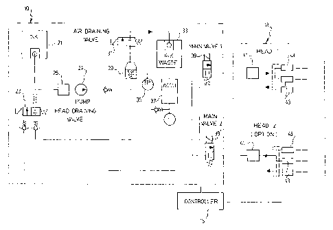
Figure 1 is a schematic representation of the printing system according to a
preferred embodiment of the invention;
Figure 2 is a photograph of a plurality of wood boards printed with the system
of
Figure 1;
Figure 3 is a representation of a code word according to a preferred
embodiment of the invention; and
Figure 4 is a representation of the system including a second print head.
DESCRIPTION OF A PREFERRED EMBODIMENT OF THE INVENTION
Referring now to Fig. 1, there is shown a schematic representation of the
system
for printing a code on an elongate article.
As mentioned in the prior art, printing a code on an elongate article has been
done
previously. However, the codes so printed are generally large, and there has
not
been previously a motivation to print a redundant code on the article.
However,
with an increase in speed of wood processing plants, and with an increase in,
the
unreadability of the previous codes, there is now a need to provide a system
and
apparatus for printing a redundant code on a elongate article which obviates
the
prior art deficiencies mentioned above.

CA 02519245 2008-01-31
4
Thus, the system 10 of the present invention comprises an ink urvit; at least
one printing head 13 and a controller 15.
The ink unit, in a preferred embodiment, includes an ink reservoir 21,
preferably
of the type "bag-in-box". Other components include a return valve 23, filter
25,
pump 24, air eliminator 29, bleeding valve 31 associated with reservoir 33,
pressure transducer 35, pressure reservoir 37 and main valve 39, all
interconnected in the usual manner. A person skilled in the art will
appreciate that
the above description is for a standard printing circuit, and that variations
are well
within the scope of the present invention.
The printing head 13 includes a filter 41 and at least two, preferably three,
valves
43. In a preferred embodiment, the valves 43 are micro-valves, which are
adapted
to open and close rapidly, spraying droplets of ink. The valves are also
preferably
aligned with each other, and laterally spaced apart.
A controller 15 controls all of the elements of the ink unit 11, and the
printing head
13.
The code that is to be printed takes up a predetermined length (footprint) on
the
piece of wood. The code word is comprised of a plurality of "bits", which may
be on
(presence of the bit) or off (absence of the bit). In a preferred embodiment,
each
bit is a longitudinal line, preferably printed with UV ink. The bits are
printed by the

CA 02519245 2005-09-15
WO 2004/082947 PCT/CA2004/000423
controller sending a signal to the valves to open for a predetermined amount
of
time. In the context of processing wood in a wood processing plant, the valves
are
only open for a few microseconds. However, given the speed at which the wood
travels, this results in each bit being approximately 1 cm long. The footprint
of the
5 code is approximately 25 cm, leaving sufficient time (or space) between
successive bits that there would not be confusion between two successive "on"
bits.
The code word according to a preferred embodiment of the invention is
comprised
of ten bits. However, it will be appreciated that more or less bits may also
fulfill the
objects of the present invention, according to the needs of the particular
user.
As mentioned previously, and as shown in Fig. 2, the code word is printed at
least
twice simultaneously, where each code is laterally spaced from the other one.
In a
more preferred embodiment, the code is printed three times, insuring better
redundancy.
Referring now to Fig. 3, there is shown three code words 51 printed
simultaneously on a piece of wood 100. As can be seen, bit 1 is on, bit 2 is
off, bit
3 is off, bit 4 is on, etc. If the code word were printed only once, errors
could occur
due to variations on the texture of the wood, presence of knots, etc. By
printing the
code at least twice, and preferably three times, the accuracy when reading the
code downstream is further increased.
The ink used for the apparatus is preferably UV as mentioned previously.
Furthermore, advantageous characteristics of the ink include fast drying, so
that
less ink is required, and the ink must be adapted to be readable on wood.
In another preferred embodiment of the invention, the apparatus of the present
invention comprises two print heads.

CA 02519245 2008-01-31
6
The second print head is useful to mark square boards, i.e. boards that have
tendency to rotate 90 degrees, in which situation the printed mark stays on
the
side and cannot be detected by the code reader. The second print head is
preferably mounted at a 90 degrees angle from the first print head.
If the second print head is used, a second main valve 39' is also provided.
Although the present invention has been explained hereinabove by way of a
preferred embodiment thereof, it should be pointed out that any modifications
to
this preferred embodiment within the scope of the appended claims is not
deemed
to alter or change the nature and scope of the present invention.

Representative Drawing
A single figure which represents the drawing illustrating the invention.
Administrative Status

2024-08-01:As part of the Next Generation Patents (NGP) transition, the Canadian Patents Database (CPD) now contains a more detailed Event History, which replicates the Event Log of our new back-office solution.

Please note that "Inactive:" events refers to events no longer in use in our new back-office solution.

For a clearer understanding of the status of the application/patent presented on this page, the site Disclaimer , as well as the definitions for Patent , Event History , Maintenance Fee  and Payment History  should be consulted.

Event History

Description Date
Time Limit for Reversal Expired 2012-03-19
Letter Sent 2011-03-18
Inactive: Correspondence - MF 2010-08-10
Grant by Issuance 2008-11-04
Inactive: Cover page published 2008-11-03
Inactive: Final fee received 2008-08-15
Pre-grant 2008-08-15
Notice of Allowance is Issued 2008-07-22
Letter Sent 2008-07-22
Notice of Allowance is Issued 2008-07-22
Inactive: Approved for allowance (AFA) 2008-05-08
Amendment Received - Voluntary Amendment 2008-01-31
Inactive: S.30(2) Rules - Examiner requisition 2007-08-02
Letter Sent 2006-10-18
Inactive: Single transfer 2006-09-08
Inactive: Courtesy letter - Evidence 2005-11-15
Inactive: Cover page published 2005-11-14
Inactive: Acknowledgment of national entry - RFE 2005-11-09
Letter Sent 2005-11-09
Application Received - PCT 2005-10-25
National Entry Requirements Determined Compliant 2005-09-15
Request for Examination Requirements Determined Compliant 2005-09-15
All Requirements for Examination Determined Compliant 2005-09-15
Application Published (Open to Public Inspection) 2004-09-30

Abandonment History

There is no abandonment history.

Maintenance Fee

The last payment was received on 2008-03-03

Note : If the full payment has not been received on or before the date indicated, a further fee may be required which may be one of the following

  • the reinstatement fee;
  • the late payment fee; or
  • additional fee to reverse deemed expiry.

Please refer to the CIPO Patent Fees web page to see all current fee amounts.

Fee History

Fee Type Anniversary Year Due Date Paid Date
Basic national fee - standard 2005-09-15
Request for examination - standard 2005-09-15
MF (application, 2nd anniv.) - standard 02 2006-03-20 2006-02-24
Registration of a document 2006-09-08
MF (application, 3rd anniv.) - standard 03 2007-03-19 2006-12-28
MF (application, 4th anniv.) - standard 04 2008-03-18 2008-03-03
Final fee - standard 2008-08-15
MF (patent, 5th anniv.) - standard 2009-03-18 2009-01-19
MF (patent, 6th anniv.) - standard 2010-03-18 2010-01-15
Owners on Record

Note: Records showing the ownership history in alphabetical order.

Current Owners on Record
AUTOLOG INC.
Past Owners on Record
ROBERT LESSARD
Past Owners that do not appear in the "Owners on Record" listing will appear in other documentation within the application.
Documents

To view selected files, please enter reCAPTCHA code :


To view images, click a link in the Document Description column. To download the documents, select one or more checkboxes in the first column and then click the "Download Selected in PDF format (Zip Archive)" or the "Download Selected as Single PDF" button.

List of published and non-published patent-specific documents on the CPD .

If you have any difficulty accessing content, you can call the Client Service Centre at 1-866-997-1936 or send them an e-mail at CIPO Client Service Centre.


Document
Description 
Date
(yyyy-mm-dd) 
Number of pages   Size of Image (KB) 
Claims 2005-09-15 2 74
Description 2005-09-15 6 246
Representative drawing 2005-09-15 1 17
Drawings 2005-09-15 3 39
Abstract 2005-09-15 1 62
Cover Page 2005-11-14 1 41
Drawings 2008-01-31 4 44
Claims 2008-01-31 2 55
Description 2008-01-31 6 218
Representative drawing 2008-10-20 1 12
Cover Page 2008-10-20 2 45
Acknowledgement of Request for Examination 2005-11-09 1 176
Reminder of maintenance fee due 2005-11-21 1 109
Notice of National Entry 2005-11-09 1 200
Request for evidence or missing transfer 2006-09-18 1 101
Courtesy - Certificate of registration (related document(s)) 2006-10-18 1 105
Commissioner's Notice - Application Found Allowable 2008-07-22 1 164
Maintenance Fee Notice 2011-04-29 1 171
PCT 2005-09-15 2 72
Correspondence 2005-11-09 1 27
Fees 2006-02-24 1 33
Fees 2006-12-28 1 40
Fees 2008-03-03 1 44
Correspondence 2008-08-15 1 41
Fees 2009-01-19 1 34
Fees 2010-01-15 1 33
Correspondence 2010-08-10 1 45
Correspondence 2011-04-29 1 90