Language selection

Search

Patent 2519695 Summary

Third-party information liability

Some of the information on this Web page has been provided by external sources. The Government of Canada is not responsible for the accuracy, reliability or currency of the information supplied by external sources. Users wishing to rely upon this information should consult directly with the source of the information. Content provided by external sources is not subject to official languages, privacy and accessibility requirements.

Claims and Abstract availability

Any discrepancies in the text and image of the Claims and Abstract are due to differing posting times. Text of the Claims and Abstract are posted:

  • At the time the application is open to public inspection;
  • At the time of issue of the patent (grant).
(12) Patent Application: (11) CA 2519695
(54) English Title: POWER SUPPLY VIA THE DATA LINES IN LOCAL AREA NETWORKS
(54) French Title: ALIMENTATION EN COURANT PAR L'INTERMEDIAIRE DES LIGNES DE DONNEES DANS DES RESEAUX LOCAUX
Status: Deemed Abandoned and Beyond the Period of Reinstatement - Pending Response to Notice of Disregarded Communication
Bibliographic Data
(51) International Patent Classification (IPC):
  • H04B 3/54 (2006.01)
(72) Inventors :
  • NEUHAUS, HANS-JUERGEN (Germany)
(73) Owners :
  • SIEMENS AKTIENGESELLSCHAFT
(71) Applicants :
  • SIEMENS AKTIENGESELLSCHAFT (Germany)
(74) Agent: SMART & BIGGAR LP
(74) Associate agent:
(45) Issued:
(86) PCT Filing Date: 2004-03-22
(87) Open to Public Inspection: 2004-12-09
Availability of licence: N/A
Dedicated to the Public: N/A
(25) Language of filing: English

Patent Cooperation Treaty (PCT): Yes
(86) PCT Filing Number: PCT/EP2004/003026
(87) International Publication Number: WO 2004107602
(85) National Entry: 2005-09-20

(30) Application Priority Data:
Application No. Country/Territory Date
103 24 373.9 (Germany) 2003-05-28

Abstracts

English Abstract


The invention relates to a particularly space-saving and cost-effective
possibility for supplying power to terminals via data lines of a local network
with the aid of a method and a device for supplying power from a current sink
(ED) via two data line pairs of a local network (LAN). The invention is
characterized in that decoupling and/or coupling of a supply voltage provided
by a voltage source (SQ) takes place between the central point of two voltage
dividers that are arranged between the two data lines of a pair.


French Abstract

L'invention concerne une possibilité particulièrement compacte et peu onéreuse pour l'alimentation en courant de terminaux par l'intermédiaire des lignes de données d'un réseau local. Le procédé et le dispositif selon l'invention pour l'alimentation en courant d'un puits de courant (ED) par l'intermédiaire de deux paires de lignes de données d'un réseau local sont caractérisés en ce qu'un couplage et/ou un découplage d'une tension d'alimentation fournie par une source de tension (SQ) se fait entre les points centraux de deux diviseurs de tension qui sont placés respectivement entre les deux lignes de données d'une paire.

Claims

Note: Claims are shown in the official language in which they were submitted.

-5-
claims
1. A method for supplying power to a current sink (ED) via
two data line pairs of a local area network (LAN),
characterized
in that a feed voltage made available by a voltage source (SQ)
is injected between the center points of two voltage dividers
which are each arranged between the two data lines of a pair,
and
in that two nonreactive resistors (R), which are equal in
value, in relation to the line termination are used as the
voltage dividers.
2. The method as claimed in claim 1,
characterized
in that the feed voltage is output between the center points of
two voltage dividers which are each arranged between the two
data lines of a pair.
3. The method as claimed in one of the preceding claims,
characterized
in that the point between the two nonreactive resistors (R) is
used as the center point.
4. The method as claimed in one of the preceding claims,
characterized
in that a circuit arrangement having electronic and/or passive
components is used as the voltage divider.
5. An apparatus for supplying power to at least one current
sink (ED) via two data line pairs of a local area network
having two voltage dividers which are each arranged
between the two data lines of a pair, and

-6-
- having center points between the two voltage dividers for
the purpose of injecting a feed voltage made available by
a voltage source (SQ),
- having two nonreactive resistors (R), which are equal in
value, in relation to the line termination as the voltage
dividers.
6. The apparatus as claimed in claim 5,
characterized
in that the two voltage dividers, which are each arranged
between the two data lines of a pair, and the center points
between the two voltage dividers are provided for the purpose
of outputting a feed voltage made available by a voltage source
(SQ).

Description

Note: Descriptions are shown in the official language in which they were submitted.


CA 02519695 2005-09-20
PCT/EP2004/003026 - 1 -
2003P07779WOUS
Description
Power supply via the data lines in local area networks
The invention relates to a method and an apparatus for
supplying power to a current sink (ED) via two data line pairs
of a local area network (LAN).
In local area networks (LAN) in which physical data
transmission takes place, for example, via 4-wire data lines
(twisted pairs), terminal devices are generally fed via
additional wires. Owing to existing installations and/or for
the purpose of using cable installations more effectively, it
may be advantageous to feed terminal devices via the ( 4 ) data
lines - i.e. without additional feed wires. This principle has
been standardized for LANs by the IEEE draft P 802.3af. For
example, a computer workstation networked via a LAN can be
supplemented by an IP landline network terminal device fed from
the LAN without the existing 8-wire standard wiring (twisted
pair) being changed or extended.
When feeding via the data lines, phantom feed circuits are
generally used. In this case, the feed voltage is fed into the
center taps of the useful signal transformers at a low
resistance. In this case, the design of the transformer must be
such that the DC feed current does not bring about saturation
of the transformer core. If this is ensured, the low-resistance
feed voltage injection does not lead to the useful signals
being influenced since the useful signals are picked up
accurately at the center tap of the transformer, the feed point
of the DC voltage (bridge circuit) . The useful signals are in
this case injected and output on the secondary side (Rx, Tx) of
the respective transformer. For phantom circuits, transformers

CA 02519695 2005-09-20
PCT/EP2004/003026 - la -
2003P07779WOUS
are used which have a relatively high space requirement, in
particular

CA 02519695 2005-09-20
PCT/EP2004/003026 - 2 -
2003P07779WOUS
a high physical height, and ~r

CA 02519695 2005-09-20
PCT/EP2004/003026 - 2fl-
2003P07779WOUS
high costs compared with other electronic standard components.
EP 1085674 A1 describes a network having at least two lines and
having network subscribers which is envisaged both for
transmitting data and for transmitting energy via the network.
The two lines in the network are designed both for data
transmission between the network subscribers and for energy
transmission from a voltage source to the network subscribers.
The data are transmitted symmetrically and differentially via
the two lines. In this case, one pole of the voltage source is
coupled to the two lines, and the network subscribers are
coupled to the other pole of the voltage source via another
electrical connection isolated from the network. The network
subscribers output the energy transmission symmetrically via
the two lines in the network. The two lines are isolated from
one another.
The object of the present invention consists in proposing a
space-saving and cost-effective option for injecting and/or
outputting a feed voltage into a local area network.
The object is achieved according to the invention by the
subject matters of the independent patent claims. Developments
of the invention are specified in the subclaims. One essential
feature of the invention consists in a feed voltage made
available by a voltage source being injected between the center
points of two voltage dividers which are each arranged between
the two data lines of a pair. One advantage of this invention
is the fact that it is a very simple and cost-effective
solution for injecting a feed voltage into a local area
network.
The invention will be explained in more detail with reference
to an exemplary embodiment illustrated in the figures, in which
in detail:
AMENDED SHEET

CA 02519695 2005-09-20
PCT/EP2004/003026 - 2~ -
2003P07779WOUS
figure 1 shows an illustration of a conventional phantom
circuit,
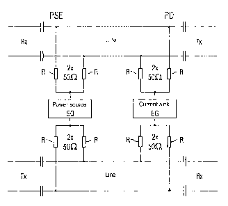
figure 2 shows an illustration according to the invention of a
circuit arrangement for injecting and outputting a
feed voltage.
Figure 1 shows a conventional phantom circuit. With this
phantom circuit, transformers U are used by means of which a
feed voltage is fed from the voltage source PSE into a data
line of a network. In the case of four-wire operation, Tx
represents a transmission direction and Rx represents a
reception direction of the data lines. The feed voltage is
tapped off at a further transformer U of the terminal device PD
and is made available to the terminal device (not illustrated
in any more detail) as a feed.
AMENDED SHEET

CA 02519695 2005-09-20
PCT/EP2004/003026 - 3 -
~nn~Dn~~~or~rnrrc
(not
Figure 2 shows an illustration of a circuit arrangement
according to the invention for injecting and/or outputting a
feed voltage. When feeding via the data lines, firstly the feed
voltage injection on the server side (PSE, power sourcing
equipment) and the feed voltage outputting on the terminal
device side (PD, powered device) are differentiated. In
principle, the two sides behave in the same way. Therefore,
only the feed side (PSE) will be described below. Reference
will only be made to the terminal device side (PD) if
necessary. In the solution according to the invention, the feed
voltage is injected and output via nonreactive resistors R. The
task of the resistors R consists in feeding in the feed
voltage, for example on the feed-in side (PSE) , from the low-
resistance voltage source PSE into the four data lines of the
local area network (LAN) such that the useful signals are not
influenced. In the case of four-wire operation, Tx represents a
transmission direction and Rx represents a reception direction
of the data lines. The useful signals are fed in on each data
line pair via the coupling capacitors. The circuit arrangement
for injecting and outputting the feed voltage can in principle
comprise different electronic and passive components. The
problem with outputting the DC power at the terminal device
(voltage sink) ED is in principle the same. A terminal device
ED may be, for example, a landline terminal device (telephone),
a wireless LAN base station or the like. Since modern local
area networks (LAN) (for example Ethernet) having twisted pair
wiring generally have a star topology, in each case 100 S2
resistors R are provided at the beginning and end for the
purpose of providing AC signal termination of the data lines.
These resistors are used in accordance with the invention for
feeding purposes in the following way: By dividing the 100 ohrrz
resistors R into in each case 2 x 50 ohm resistors R, the
center point of this voltage divider is free of signals. The

CA 02519695 2005-09-20
PCT/EP2004/003026 - 4 -
2003P07779WOUS
resistors R in the voltage divider are connected in series. The
injecting and outputting of the feed voltage can therefore take
place at the center point of the voltage divider without the
signals being influenced.

Representative Drawing
A single figure which represents the drawing illustrating the invention.
Administrative Status

2024-08-01:As part of the Next Generation Patents (NGP) transition, the Canadian Patents Database (CPD) now contains a more detailed Event History, which replicates the Event Log of our new back-office solution.

Please note that "Inactive:" events refers to events no longer in use in our new back-office solution.

For a clearer understanding of the status of the application/patent presented on this page, the site Disclaimer , as well as the definitions for Patent , Event History , Maintenance Fee  and Payment History  should be consulted.

Event History

Description Date
Time Limit for Reversal Expired 2009-03-23
Application Not Reinstated by Deadline 2009-03-23
Deemed Abandoned - Failure to Respond to Maintenance Fee Notice 2008-03-25
Inactive: Cover page published 2005-12-05
Letter Sent 2005-11-15
Inactive: Notice - National entry - No RFE 2005-11-15
Application Received - PCT 2005-10-27
National Entry Requirements Determined Compliant 2005-09-20
Application Published (Open to Public Inspection) 2004-12-09

Abandonment History

Abandonment Date Reason Reinstatement Date
2008-03-25

Maintenance Fee

The last payment was received on 2007-02-15

Note : If the full payment has not been received on or before the date indicated, a further fee may be required which may be one of the following

  • the reinstatement fee;
  • the late payment fee; or
  • additional fee to reverse deemed expiry.

Patent fees are adjusted on the 1st of January every year. The amounts above are the current amounts if received by December 31 of the current year.
Please refer to the CIPO Patent Fees web page to see all current fee amounts.

Fee History

Fee Type Anniversary Year Due Date Paid Date
Basic national fee - standard 2005-09-20
Registration of a document 2005-09-20
MF (application, 2nd anniv.) - standard 02 2006-03-22 2006-02-10
MF (application, 3rd anniv.) - standard 03 2007-03-22 2007-02-15
Owners on Record

Note: Records showing the ownership history in alphabetical order.

Current Owners on Record
SIEMENS AKTIENGESELLSCHAFT
Past Owners on Record
HANS-JUERGEN NEUHAUS
Past Owners that do not appear in the "Owners on Record" listing will appear in other documentation within the application.
Documents

To view selected files, please enter reCAPTCHA code :


To view images, click a link in the Document Description column. To download the documents, select one or more checkboxes in the first column and then click the "Download Selected in PDF format (Zip Archive)" or the "Download Selected as Single PDF" button.

List of published and non-published patent-specific documents on the CPD .

If you have any difficulty accessing content, you can call the Client Service Centre at 1-866-997-1936 or send them an e-mail at CIPO Client Service Centre.


Document
Description 
Date
(yyyy-mm-dd) 
Number of pages   Size of Image (KB) 
Claims 2005-09-19 2 49
Description 2005-09-19 7 171
Drawings 2005-09-19 2 26
Abstract 2005-09-19 1 13
Representative drawing 2005-12-01 1 7
Reminder of maintenance fee due 2005-11-22 1 109
Notice of National Entry 2005-11-14 1 192
Courtesy - Certificate of registration (related document(s)) 2005-11-14 1 106
Courtesy - Abandonment Letter (Maintenance Fee) 2008-05-19 1 178
Reminder - Request for Examination 2008-11-24 1 117
PCT 2005-09-19 5 167