Note: Descriptions are shown in the official language in which they were submitted.
CA 02519933 2005-09-21
WO 2004/084624 PCT/AU2004/000380
1
Equine Fitness Monitoring'
Background of the Invention
The present invention relates to apparatus and a method for monitoring the
status
of a horse, and in particular to apparatus including a blanket incorporating a
sensor, such as a heart rate sensor.
Description of the Prior Art
The reference to any prior art in this specification is not, and should not be
taken
as, an acknowledgment or any form of suggestion that the prior art forms part
of
the common general knowledge.
Monitoring equine fitness is extremely important in ensuring animal health and
to
provide performance management. For example, it has been shown that there is
value in monitoring certain parameters over time to provide a more
quantitative
assessment of health. These parameters can be measured via heart rate
monitors and the like to provide maximum effectiveness.
Typically, monitoring is achieved by passively monitoring the animal during
training, based on feedback from trainers and jockeys via trackwork results,
or via
controlled studies.
In the case of controlled studies, this may achieved using treadmill studies,
which
rely on the implementation of a standardised protocol in controlled
environments.
In particular, such tests are typically performed based on precise exercise
protocols, with the speeds and durations for each step of an exercise test
being
highly repeatable.
From such studies, it has been suggested that the velocity at a heart rate of
200
beats per minute (hereinafter referred to as "V200") can be used as an
expression
of the maximal aerobic power of the horse. As an expression for the heart
rate/velocity relationship, the interpolated or extrapolated velocity at heart
rate 200
(V200) may be used as it is close to the workload at which onset of blood
lactic
acid accumulation (anaerobic threshold) occurs. Such tests have proved to be
CA 02519933 2005-09-21
WO 2004/084624 PCT/AU2004/000380
2
useful and reliable tool for evaluation of training effects, and have shown a
negative correlation between V200 and treadmill running speed, suggesting that
faster horses attain a heart rate of 200 beats per minutes at a lower speed
than
slower horses.
However, such test have also shown a number of problems. For example, the
horses need to be acclimatised to treadmill exercise, and responses to
acclimatisation are unpredictable in individual horses. In addition to this,
locomotion during treadmill exercise is also different to that on the track.
Stride
frequencies at identical trot and gallop speeds are greater on a racetrack
than on
a treadmill and such studies, do not therefore typically reflect practical
exercise
conditions.
An example of a field test is described in Kobayashi (1999), in which V200 was
calculated with an incremental field exercise test in racehorses. This was the
study reported the practical application of V200 for the evaluation of
training
effects in the young Thoroughbreds, but was limited to specific tests in
limited
environments, and did not therefore monitor the horse under standard
conditions,
which tends to lead to unreliability of results.
For example, environmental conditions, such as high and low ambient
temperature and relative air humidity can be an important factor during the
conduct of field exercise tests. Furthermore, field studies usually do not
take into
account air resistance that the racehorse has to face on the track, and
provide
only a limited range of measurements.
Such studies do not therefore represent practical conditions in which horses
train
or race. Thus, in Kobayashi, high V200 was found, due to a number of factors
including:
~ high heart rates during trotting, which is indicative of excitability;
~ gait changes that were not carried out "smoothly"; and,
~ phases of rapid acceleration during gallop exercise.
CA 02519933 2005-09-21
WO 2004/084624 PCT/AU2004/000380
3
Thus, whilst specific tests may be useful in examining a specific fitness
area,
under specific conditions, these tests are generally time consuming and of
limited
value in practical applications.
In addition to this, such tests generally require specialist equipment and
does not
therefore allow practical fitness testing of horses. For example, US-6,504,483
which describes a system for electronically monitoring vital signs of a moving
horse. This relies on the provision of monitoring equipment around a pre-
designated track, thereby severely limiting the circumstances in which the
device
may be used.
Solutions have been proposed for allowing heart rate to be measured in situ.
For
example, US-4,540,001 and US-4,478,225 relate to the provision of a heart
monitor for horses, with the heart monitor being incorporated either in the
saddle
itself or in a saddle girth. However, these techniques suffer from a number of
drawbacks.
Firstly, saddles tend to be expensive, and providing such monitoring equipment
therein further increases article cost. In addition to this, if a fault
develops with the
monitoring equipment, it can be costly to replace the equipment and the
saddle.
Secondly, saddles tend to be subject to high stresses in use, thereby reducing
the
efFectiveness of the monitoring equipment.
Thirdly, saddles in generally are not suitable for mounting monitoring
equipment,
and this tends to reduce the comfort of the saddles to both the rider and the
horse, thereby impairing performance during testing.
This also tends to restrict the re-use of the apparatus with different horses,
such
that trainers will typically need a respective saddle for each horse.
Summary of the Present Invention
In a first broad form the present invention provides apparatus for monitoring
the
status of a horse, wherein the apparatus includes:
(a) a blanket having a first sensor, the first sensor being adapted to
generate
indicating data indicative of at least one health status indicator; and,
CA 02519933 2005-09-21
WO 2004/084624 PCT/AU2004/000380
4
(b) a second sensor for generating position data indicative of the position of
the horse, wherein, in use, a processing system is adapted to determine
the health status of the horse in response to the indicating data and the
position data.
Typically the health status indicator includes at least one of the horse's:
(a) heart rate;
(b) blood pressure;
(c) temperature; breathing rate;
(d) blood flow rate; and,
(e) blood oxygenation levels.
Typically the second sensor is formed from a GPS sensor.
The second sensor is usually adapted to be worn by a rider in use, and wherein
the blanket further includes a connector for coupling the second sensor to the
blanket in use.
The second sensor may be provided in the blanket.
The blanket may further include a power supply for coupling to the first and
second sensors.
The power supply typically includes at least one battery connected to a first
part of
an inductive coupling, and wherein, in use, the battery is recharged by
connecting
the first part of the inductive coupling to a second part of the inductive
coupling,
the second part being coupled to a power supply.
The blanket typically further includes a communications device coupled to the
first
and second sensors to thereby transfer at least one of the indicating and
position
data to a remote computer system.
The blanket usually further includes a store coupled to the first and second
sensors to thereby store at least one of the indicating and position data to a
remote computer system.
CA 02519933 2005-09-21
WO 2004/084624 PCT/AU2004/000380
The apparatus can include a processing system coupled to at least one of the
first
and second sensors for at least partially analysing at least one of the
indicating
and the position data.
The processing system may be coupled to a display, the display being adapted
to
5 provide an indication to the rider in accordance with at least one of the
indicating
and the position data.
The first sensor can be a heart rate sensor and wherein the blanket includes
at
least one electrode coupled to the heart rate sensor and positioned so as to
be in
contact with the horse in use.
The blanket can include at least one wire embedded in the blanket material,
the
wire being adapted to connect the heart rate sensor to the at least one
electrode.
The blanket may be a woven blanket and wherein the wire is integrated within
the
weave of the blanket.
The first sensor can be removably mounted to a pouch, the pouch including one
or more connectors adapted to cooperate with corresponding detectors provided
on the sensor, to thereby couple the sensor to the blanket.
In a second broad form the present invention provides apparatus for monitoring
the status of a horse, wherein the apparatus includes a processing system
adapted to:
(a) receive, from a first sensor provided in a horse blanket, indicating data
indicative of at least one health status indicator;
(b) receive, from a second sensor, position data indicative of the position of
the
horse; and,
(c) determine the health status of the horse in accordance with the indicating
data and the position data.
The processing system can be adapted to receive the position and indicating
data
from apparatus according to the first broad form of the invention.
The processing system can include a communications device for receiving the
indicating and position data.
CA 02519933 2005-09-21
WO 2004/084624 PCT/AU2004/000380
6
The processing system may determine the health status of the horse using a
predetermined algorithm, the predetermined algorithm defining a relationship
between the at least one health status indicator and movement of the horse.
The predetermined algorithm typically includes:
(a) determining at least a low heart rate during low speed exercise;
(b) determining a number of heart rates during high speed exercise;
(c) perform linear regression to calculate a linear regression line:
(d) calculate, using the linear regression line, the velocities at at least
one of:
(i) heart rates of 200 beats per minute (V200); and,
(ii) HRmax (VHRmax); and,
(e) determine a fitness indicator in accordance with the calculated at least
one
velocity
The line regression line can determined in accordance with:
HR=a+bV,
where HR = heart rate;
a = constant;
b = constant; and,
V = velocity.
The method usually further includes deleting any outlier values, which can
include
at least one of:
(a) deleting all results with a velocity of less than 40 kph;
(b) deleting all results during the period after exercise (from the time of
occurrence of HRmax);
(c) deleting all data equal to at least one of:
(i) HRmax;
(ii) HRmax-1;
(iii) HRmax - 2; and,
(iv) HRmax - 3;
(d) deleting all data where there has been an increase in velocity, but that
increase was not accompanied by an increase in HR;
CA 02519933 2005-09-21
WO 2004/084624 PCT/AU2004/000380
7
(e) deleting any data points which have a HR that is more than 10 beats per
minute above the regression line at that speed, and recalculate the
regression line if such outliers are deleted.
The processing system can be adapted to obtain indicating data and position
data
relating to a number of horses, the processing system being adapted to
determine
the health status of each of the number of horses.
In a third broad form the present invention provides apparatus for monitoring
the
status of a horse, wherein the apparatus includes a processing system adapted
to:
(a) receive, from a first sensor, indicating data indicative of the heart rate
of the
horse;
(b) receive, from a second sensor, position data indicative of the position of
the
horse;
(c) determine from the position data, movement data indicative of the rate of
movement of the horse; and,
(d) determine the health status of the horse in accordance with a
predetermined algorithm, the predetermined algorithm defining a
relationship between the heart rate and the rate of movement of the horse.
The predetermined algorithm typically includes:
(a) determining at least a low heart rate during low speed exercise;
(b) determining a number of heart rates during high speed exercise;
(c) perform linear regression to calculate a linear regression line:
(d) calculate, using the linear regression line, the velocities at at least
one of:
(i) heart rates of 200 beats per minute (V200); and,
(ii) HRmax (VHRmax); and,
(e) determine a fitness indicator in accordance with the calculated at least
one
velocity.
In a fourth broad form the present invention provides a system for monitoring
the
status of a horse, wherein the system includes:
(a) a blanket having a first sensor, the first sensor being adapted to
generate
indicating data indicative of at least one health status indicator; and,
CA 02519933 2005-09-21
WO 2004/084624 PCT/AU2004/000380
8
(b) a second sensor for generating position data indicative of the position of
the horse; and,
(c) a processing system, the processing system being responsive to the
indicating and position data to thereby determine the health status of the
horse.
The system may including apparatus according to the first broad form of the
invention.
In a fifth broad form the present invention provides a method of monitoring
the
health status of a horse, wherein the method includes:
(a) using a blanket having a first sensor to generate indicating data
indicative
of at least one health status indicator; and,
(b) using a second sensor to generate position data indicative of the position
of
the horse; and,
(c) determining the health status of the horse in response to the indicating
data
and the position data.
The method can be perFormed using the apparatus of the first broad form of the
invention.
In a sixth broad form of the invention provides a method of monitoring the
health
status of a horse, wherein the method includes, in a horse blanket:
(a) generating indicating data using a first sensor, the indicating data being
indicative of at least one health status indicator;
(b) obtaining position data from a second sensor, the position data being
indicative of the position of the horse; and,
(c) providing the indicating data and the position data to a processing
system,
the processing system being responsive to the indicating data and the
position data to determine the health status of the horse.
The method can be performed using the apparatus of the first broad form of the
invention.
In a seventh broad form the present invention provides a method of monitoring
the
health status of a horse, wherein the method includes, in a processing system:
CA 02519933 2005-09-21
WO 2004/084624 PCT/AU2004/000380
9
(a) receiving, from a first sensor provided in a horse blanket, indicating
data
indicative of at least one health status indicator;
(b) receiving, from a second sensor, position data indicative of the position
of
the horse; and,
(c) determining the health status of the horse in accordance with the
indicating
data and the position data.
The method can be performed using the apparatus of the first broad form of the
invention.
In an eighth broad form the present invention provides apparatus for
monitoring
the status of a horse, wherein the apparatus includes a processing system
adapted to:
(a) receive, from a first sensor, indicating data indicative of the heart rate
of the
horse;
(b) receive, from a second sensor, position data indicative of the position of
the
horse;
(c) determine from the position data, movement data indicative of the rate of
movement of the horse; and,
(d) determine the health status of the horse in accordance with a
predetermined algorithm, the predetermined algorithm defining a
relationship between the heart rate and the rate of movement of the horse.
The predetermined algorithm typically includes:
(a) determining at least a low heart rate during low speed exercise;
(b) determining a number of heart rates during high speed exercise;
(c) perform linear regression to calculate a linear regression line:
(d) calculate, using the linear regression line, the velocities at at least
one of:
(i) heart rates of 200 beats per minute (V200); and,
(ii) HRmax (VHRmax); and,
(e) determine a fitness indicator in accordance with the calculated at least
one
velocity.
The method can be performed using the apparatus of the first broad form of the
invention.
CA 02519933 2005-09-21
WO 2004/084624 PCT/AU2004/000380
Brief Description of the Drawings
An example of the present invention will now be described with reference to
the
accompanying drawings, in which: -
Figure 1 is a schematic diagram of a first example of a saddle blanket system
5 incorporating apparatus for monitoring horses;
Figure 2 is a schematic side view of the blanket system of Figure 1;
Figure 3 is a schematic diagram of an example of apparatus for analysing
signals
generated by the blanket system of Figure 1;
Figure 4 is a schematic diagram of a second example of a saddle blanket system
10 incorporating apparatus for monitoring horses;
Figure 5 is a schematic side view of the blanket system of Figure 4;
Figure 6 is a schematic diagram of a charging system;
Figure 7 is a schematic plan view of the blanket system of Figure 4;
Figure 8 is a schematic diagram of an example of a distributed architecture
for
monitoring a number of horses;
Figure 9 is a schematic diagram of an example of a processing system of Figure
8;
Figure 10 is an example of heart rate and velocity determined using the system
of
Figure 1 or Figure 4;
Figures 11A-11D are graphs showing a determined linear regression for the data
shown in Figure 10;
Figure 12 is a graph showing data collected from trials of the system of
Figure 1.
Detailed Description of the Preferred Embodiments
An example of a saddle blanket incorporating apparatus for monitoring horse
vital
signs and/or position will now be described with reference to Figures 1 and 2.
CA 02519933 2005-09-21
WO 2004/084624 PCT/AU2004/000380
11
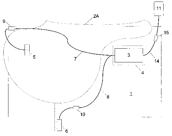
As shown; the blanket 1 is designed to be worn by a horse 2, under a saddle
2A.
The blanket 1 incorporates a module 3, which is sewn into the blanket, as
shown
at 4. The blanket generally has a layer of foam, allowing the module 3 to be
recessed therein, such that the blanket lies flush against the horse, without
the
module protruding inwards, and digging into the horse. The blanket is also
typically formed from specialised materials to enhance function and
durability, for
example to provide shock absorption, and air flow.
The module 3 is connected to two electrodes 5, 6, via respective cables 7, 3.
In
order to ensure correct sensing of the heart rate the electrodes 5, 6 are
positioned
respectively on the top shoulder of the horse and one placed above the heart,
just
below the girth. In this example, the electrodes may be provided separately to
the
blanket, with respective connectors 9, 10 being provided, to allow the
electrodes
5, 6 to be fixed to the horse, and then connected to the module 3, when the
blanket is placed on the horse 2. Normal industry practise is to place a
folded
towel underneath the saddle blanket to absorb the sweat. In this instance,
Velcro
provided on the towel, in the electrode position, can be used to hold the
electrode
in the correct position. Alternatively, however, Velcro could be placed on the
underside of the blanket to hold the electrode in place. Similarly, for the
girth
position, the electrode can be built into a girth cover which would be slid
over the
girth as the saddle is placed on the horse. In both cases, the cables extend
through the blanket to the relevant electrode position, thereby connecting the
electrode to the module 3.
In used, the horse's skin can simply be wetted, before the electrodes are
positioned thereon. The electrodes are then held in place, as described above,
thereby providing a simple means for ensuring correct electrode positioning.
In this example, the module 3 is also connected to an antenna 11, which is
used
to receive signals indicative of the horse's position, such as GPS signals.
The
antenna 11 is mounted to the jockey 12, for example on the helmet 13, and is
connected to the module 3 via a cable 14. The antenna is situated on the
helmet
to ensure successful receiving of the GPS signals, in particular as the
horse's bulk
will shield antennas positioned in the blanket to some extent, although
alternative
CA 02519933 2005-09-21
WO 2004/084624 PCT/AU2004/000380
12
positions may be used. The cable 14 includes a connector 15, which allows the
jockey to mount the horse before connecting the GPS system to the blanket. In
addition to this, the cable 14 and connector 15 also act as a safety feature,
such
that if a rider falls off the horse, the cable 14 will pull out in a straight
direction,
disengaging the connector, so that there is a reduced chance of jerk to rider.
In use, the module 3 typically includes processing electronics which is
adapted to
monitor signals generated by the electrodes 5, 6 to determine the heart rate
therefrom, as well as to monitor position indication signals received from the
GPS
system 11.
Persons skilled in the art will appreciate that a number of different
configurations
may be used to obtain this functionality. In one example, shown in Figure 3,
the
processing electronics include a processor 30, a memory 31, a communications
system 32, and an external interface 33, coupled together via a bus 34. In
use,
signals from the electrodes 5, 6, and the antenna 11 are received via the
external
interface 33, and passed on to the processor 30, for preliminary processing.
In particular, in this example, the processor 30 is adapted to determine the
current
heart rate and position of the horse, and then store these as heart rate and
position data in the memory 31. It will therefore be appreciated that the
processing electronics can be formed from custom hardware, such as a DSP, and
corresponding memory, and/or through the use of applications software
operating
on a suitable generic processing system.
The heart rate and position data can then be further processed to allow a
health
status of the horse to be determined. This is typically performed by a remote
processing system, such as a computer or the like. Accordingly, the
communications system 32 can be used to transfer the data to the computer
system. This can be performed via a wireless radio based transmission system.
This may include short range communications systems, such as Wi-Hi, Bluetooth,
or the like. Alternatively, long range radio connections, such as the GSM or
other
mobile phone networks, can be used. As a further alternative wired connections
can be used to transfer data at the end of an exercise period, as will be
appreciated by persons skilled in the art.
CA 02519933 2005-09-21
WO 2004/084624 PCT/AU2004/000380
13
In order to track horses that are in training over a long distance, for
example over
a typical training track, which can be up to 10 Km in length, long range radio
communications is typically used. This can be achieved using a high powered
radio modem, which will typically utilise an antenna sewn into the saddle
blanket.
The antenna typically runs down the back of the saddle blanket, but may be
formed from shorter stubby antennas attached to one of the modules, such as
the
module 3.
The polarisation of the antenna will depend on the size and shape of the
horse,
and different configurations may therefore be provided in different sizes of
blankets. A circularly polarised antenna provided at the receiving end, helps
overcome any problems that may arise due to polarisation of the transmitted
signal.
Because the orientation of the horse can be in any direction, the antenna in
the
saddle blanket is preferably provided on both sides of the horse. The antenna
may also be shielded to help reduce exposure of the horse to RF signals, as
well
as to help project signals.
It will also be appreciated that the processing electronics provided in the
module 3
may perform the analysis, as will be described in more detail below.
In any event, the position data is used to determine the rate of movement of
the
horse over a time period, with this information being used in conjunction with
the
corresponding heart rate, to determine the horse health status.
This can be achieved without the use of a standardised exercise test protocol,
and
associated analysis procedure are used in accordance with the following
methodology:
1. Identify the lowest pair of heart rates during trotting;
2. Identify the maximal heart rate (highest) (HRmax);
3. Delete all results with velocity less than 40 kph;
4. Delete all results during the period after exercise (from the time of
occurrence of HRmax);
CA 02519933 2005-09-21
WO 2004/084624 PCT/AU2004/000380
14
5. Delete all data equal to HRmax, or equal to HRmax -1, HRmax - 2, or
HRmax - 3;
6. Delete all data where there has been an increase in velocity, but that
increase was not accompanied by an increase in HR;
7. With the trotting and remaining data from high speed exercise, calculate
the linear regression line;
HR = a + b (velocity)
8. Inspect the scatter plot and linear regression line. Delete any data
points which have a HR that is more than 10 beats per minute above
the regression line at that speed (ie, delete residuals of more than +10),
and recalculate the regression line if such outliers are deleted.
9. Using the linear regression equation, calculate the velocities at heart
rates of 200 beats per minute (V200), and at the HRmax (VHRmax).
The trotting heart rate is determined after the horse has been trotting for at
least
three minutes, as this allows the spleen reaction to die down after the horse
has
commenced exercise.
In addition to this, when the horse reaches the highest heart rate, this will
typically
result in the detection of a group of five heart rates, accompanied by
increasing
velocities, in which case the first heart rate is used.
The algorithm is therefore typically implemented using a processing system to
assist with the data analysis, which may therefore be performed automatically,
manually, or through a combination of automated or manual operation.
Accordingly, in use, the blanket and associated sensors can be mounted to the
horse substantially as described above, allowing information on the horse
health
status to be determined whilst the horse is being ridden. The collected data
can
then be transferred to a computer system, either whilst the horse is being
ridden,
or at the end of the ride, thereby allowing the health status to be
immediately
determined.
CA 02519933 2005-09-21
WO 2004/084624 PCT/AU2004/000380
Variations
A number of alternatives and additional features will now be described with
respect to the accompanying drawings.
In a second example of the saddle blanket, shown in Figure 4 and 5, the module
3
5 is positioned in a pouch 24, thereby allowing the module to be removed from
the
blanket. In order to achieve this, the module is connected to the cables 7, 8,
and
14 via respective connectors 15, 16, 17, as shown.
This allows the module to be removed and replaced or repaired, if required..
In
addition to this, the module can be removed to allow the heart rate and
position
10 data to be downloaded therefrom. In this example, the communications system
32 may therefore correspond to a connection, such as a USB port, or the like.
Alternatively, the memory 31 can be provided in the form or a removable media,
such as a smart card, or the like, from which the data can be downloaded on to
a
computer.
15 In this example, the electrode 5 is integrally formed within the blanket,
with the
electrode 6 remaining attached to the blanket at all times, thereby removing
the
requirement for the connectors 9, 10.
Furthermore, the system includes one or more display devices 18 for providing
status information to the rider. In this example, the display devices can be
connected to the processing electronics, either wirelessly, for example by
using a
short-range communications protocol, such as Bluetooth, or through the use of
cables 19, as shown. In this case, if one of the display devices is worn by
the
rider as shown, it is typical for the cable 19 to be provided with a connector
20,
adapted to disengage if the rider falls.
The displays may be provided either behind the ears of the horse, or on the
rider,
as shown, and may be implemented using liquid crystal displays, a heads up
display (HUD), or the like. Preferably the display is readable in the dark and
in
daylight conditions, in which case a backlit display may be needed, which will
place extra demands on the battery life. Accordingly, the display is typically
provided with a push button backlight activation system, which will activate
the
CA 02519933 2005-09-21
WO 2004/084624 PCT/AU2004/000380
16
backlight for a predetermined time period, allowing the display to be viewed
regardless of ambient conditions.
The display is light enough to mount on the horses bridle on the back of the
horses head, or may be worn by the rider, as shown. If mounted on the horse,
this
is typically achieved using some form of mounting strap so as to not upset the
horse.
The information displayed to the rider will depend on the respective
implementation, and the information required. For example, the information may
include no more that the current heart rate and the current position or speed
of the
horse.
Alternatively, the display devices can be adapted to show the current health
status
of the horse. This can be achieved by having the health status, as determined
real time by the remote computer, relayed back to the module 3, via the
communications system 32, and then displayed as required. Alternatively, the
health status can be determined by having the processing electronics perform
analysis of the heart rate and position data, substantially as described
above, to
thereby determine the health status of the horse, and display this to the
user. In
this case, the health status may be downloaded to a remote computer system at
the end of the ride, in the same manner as the heart rate and position data,
as
described above.
In addition to this, the displays can incorporate a communications device, to
thereby allow communication between the rider and a trainer, owner or the
like.
This may be achieved using voice and text messages, or the like. Pre-
programmed work routines and instructions could also be display to the rider.
As a further variation, positional information determined from the GPS system
can
also be used to initiate messages, functions and the like. This can be used
for
example, to prompt the rider to perform predetermined actions, such as
trotting,
cantering, or the like.
The GPS antenna 11 may also be integrated into tyke horse blanket, or form
part
of an integrated GPS system, including a dedicated GPS processor and an
CA 02519933 2005-09-21
WO 2004/084624 PCT/AU2004/000380
17
antenna which is provided within a respective pouch 21, as shown.
Alternatively,
a dedicated GPS processor can be provided on or in the rider's helmet with an
associated transmitter and power supply, to allow the position data to be
transferred to the module 3, for example, using a Bluetooth communications
link.
It will be appreciated that other parts of the module 3 and the associated
processing electronics may be provided on or in the rider's helmet.
In this case, a wireless connection may be used to link the GPS system to the
display 18 and/or the module 3. In this case, the GPS system may be provided
with a unique identifier, to allow module 3 to ensure signals are received
from the
correct GPS system. In this case, by associating the identifier with the
jockey, this
allows the system to distinguish the jockey, and associate this with an
identifier
provided for the horse in the display device 18 or the electronics module 3,
as
described below.
Typically, whilst there would be no more than 30 - 100 horses training at a
time,
an electronic identifier provided with the GPS system provides a significant
number of combinations allowing horses, blanket systems and jockeys to be
identified uniquely during the training session.
In one example, differential GPS is used to provide greater accuracy in
determination of horse position. However, this level of accuracy is not
generally
required and standard accuracy GPS may be used, removing the need for the
antenna 11.
In general, GPS systems require recent satellite information to be able to
provide
accurate information. This initiation process typically takes about three to
four
minutes. Accordingly, in one example, the remote processing system 50 can be
used to provide the latest information to the onboard GPS system via a
communications link, thereby reducing start up time. This may typically be
performed while the blanket is being stored, at which time it is also typical
to
perform a systems check to verify operational status. This may be carried out
whilst the blankets are on a special rack for charging, as described in more
detail
below.
CA 02519933 2005-09-21
WO 2004/084624 PCT/AU2004/000380
18
A feature that may be utilised is for the module 3 to be provided with an
integral,
rechargeable power supply, such as a battery. In this example, the battery can
be
coupled to a charging system through a wireless inductive coupling mechanism,
as shown for example in Figure 6. In this example, the battery 40 is coupled
to a
coil 41, which cooperates with a coil 42 provided in a charging system 43. By
providing the coil 41 around a recess 44 in the module 3, which cooperates
with a
protrusion 45 in the charging system 43, this ensures maximum inductive
coupling
between the coils 41, 42, thereby improving charging efficiency. In this
instance,
the protrusion may advantageously form part of a hanging mechanism, allowing
the battery to be charged when the blanket is hung up, and is not in use.
A separate power supply module 70 may also be provided depending on the
implementation. If multiple modules 3, 11 are used, the modules 3, 70 may be
positioned on either side of the saddle 2A, as shown in the plan view in
Figure 7.
In this case, the modules can be connected via a cable 71 running around the
rear of the saddle, as shown, to thereby avoid pressure points on the horse.
This
has the additional benefit of balancing the weight distribution of the
blanket,
thereby ensuring the blanket does not slip off when placed on the horse.
In the examples set out above, the module 3, and the optional power supply and
GPS modules are preferably located in close proximity to the saddle, such that
the
modules are held in place by the saddle, reducing movement, although this is
not
essential. In general, continuous monitoring of horse position is not
required, as
this can unduly drain the batteries. This can therefore be overcome by
entering
weigh points and triggers in the GPS micro controller, that could activate the
recording or reporting of velocity and heart rate under different
circumstances.
Weigh points could also be used to notify the trainer if a horse was not
complying
with the specified training regime. They can also be used to indicate if a
horse is
leaving or returning to the stable so that logged data can be downloaded out
of
the saddle blanket.
It will be appreciated from the above, that a number of different system may
be
monitored by a processing system 50, as shown for example, in Figure 8. In
this
example, the processing system 50 communicates with a number of modules 3,
CA 02519933 2005-09-21
WO 2004/084624 PCT/AU2004/000380
19
which may be achieved via directly, or via a suitable communications network
51,
such as a LAN, WAN, the Internet, the mobile phone network, or the like. The
transfer of data is preferably performed wirelessly, but may also be performed
through wired connections at the end of a ride as described above.
An example of a suitable processing system 50 is shown in Figure 9. In
particular, the processing system 60 generally includes at least a processor
60, a
memory 61, an input/output (I/O) device 62, such as a keyboard and display,
and
an external interface 63 coupled together via a bus 64. The processing system
can be coupled a database 52, and the network 51, via the external interface
65.
Accordingly, it will be appreciated that the processing system 10 may be
formed
from any suitable processing system, such as a suitably programmed PC,
Internet
terminal, lap-top, hand-held PC, or the like, which is typically operating
applications software to enable data transfer and analysis.
In this case, each module 3 will be provided with a respective identifier,
which is
used to identify the source of the respective heart rate and position data,
when it
is transferred to the processing system 50. The identifier can be associated
with
the respective horse at the start of the ride by providing an indication of
the
module 3 being used, and an indication of the horse's identity. The system may
use ID chips inserted under the animal skin for an identification process.
The processing system 50, can then store received data in a database 52, and
. use the data to determine the health status of a respective horse, which can
then
be displayed using the I/O device 62, or transferred to a remote processing
system for subsequent display. For example, the processing system 50 can be
adapted to generate an alert if the determined health status falls outside a
predetermined range which represents a situation in which the horse may be
harmed if riding continues.
This allows a single operator to monitor a number of horses being trained, to
ensure that the horses are not trained in a manner which is detrimental to the
horses health, and to generally observe horse fitness.
CA 02519933 2005-09-21
WO 2004/084624 PCT/AU2004/000380
It will therefore be appreciated that this allows owners and trainers to gain
access
to results and details of monitoring via the Internet. Furthermore, it will be
appreciated that the processing system 50 may be operated by an entity which
provides analysis services, and which therefore operates to receive and
analyse
5 data, providing details of the determined results to owners and trainers.
Throughout the description and claims, the term horses should be understood to
include racehorses, camels, llamas, greyhounds, performance animals, such as
racing animals, and other non-performance animals, such as non-racing horses.
Furthermore, the description has focussed on the use of a heart rate monitor
for
10 measuring a vital sign of the horse. However, other monitoring techniques
can be
used to monitor different vital signs as an alternative, or an addition to
measuring
heart rate. In particular, monitoring can be performed by measuring:
~ blood pressure;
~ temperature;
15 ~ breathing rate;
~ blood flow rate; and,
~ blood gas levels.
In addition to this, it is also possible to provide sensors for measuring
environmental conditions, such as external temperature and other weather
20 conditions. This allows a detailed record of the conditions under which the
horse
was trained to be ascertained and stored automatically.
Specific Example
In one example, recordings of heart rate and velocity during trotting on a
sand
track and gallops on a grass track were performed three times during a four
week
period in 8 Thoroughbred racehorses (3 geldings, 3 fillies and 2 colts; aged 2
to 4
years old).
Heart rates were recorded by Polar heart rate meters provided in a saddle
blanket, with speed being measured using the GPS system, which can be used to
calculate velocity with a speed accuracy: 0.36kph. In this example, the
blanket
incorporates a 12 channel receiver interface to connect with a personal
computer.
CA 02519933 2005-09-21
WO 2004/084624 PCT/AU2004/000380
21
After inspection of the records of five-second averages of heart rate and
velocity
(0.2 Hz recordings) obtained during exercise, regressions of heart rate on
velocity
were constructed to derive V200.
The typical training exercise included 5 minutes trotting (mean trot speeds
ranged
from 4.1 to 4.6 m/s). After a brief period of walking, horses then galloped
over
800-1000 metres on a grass track. This allowed for steady natural changes in
gait, and represent the fitness and performance of the horse in general riding
conditions.
An example of the heart rate and velocity determined using the system
described
above is shown in Figure 10.
To demonstrate the varying degrees of accuracy of the methodology over
different
conditions, four methods of calculation of V200 were used, as follows:
~ "Gallop with outliers" used only gallop heart rates, and included all heart
rate and velocity records;
~ "Gallop without outliers" used only gallop heart rates and excluded the
heart rate outliers (outliers were defined as heart rates that were more than
10 bpm higher than another heart rate at a similar speed);
~ "Trot plus Gallop with outliers" combined "Gallop with outliers" and trot
data;
~ "Trot plus gallop without outliers" combined "Gallop without outliers" and
trot data.
Graphs for each of these scenarios are set out in Figures 11A to 11 D
respectively.
For trot data, the average of the heart rate and velocity during the final 50
seconds of trotting were used, to thereby ensure gait changes did not have an
undue impact.
A minimum speed of 11.1 m/s was used as the criteria for identification of the
beginning of the gallop exercise, and only heart rates during periods of
increasing
speed were used during gallops, with occasional losses of heart rate or speed
during exercise being excluded from the analyses, thereby reduce the effect of
obstacles and the like.
CA 02519933 2005-09-21
WO 2004/084624 PCT/AU2004/000380
22
From this, a linear regression is determined, as described above, allowing
V200
and the regression coefficient R2 to be determined. The results from this
analysis
are as follows:
~ Gallop with outliers - R2 = 0.79;
- V200* = 14.4 m/s;
~ Gallop without outliers - RZ = 0.88;
- V200* = 14.3 m/s;
~ Trot plus Gallop with outliers - R2 = 0.98;
- V200* = 15.0 m/s;
~ Trot plus gallop without outliers - R2 = 0.99;
- V200* = 14.8 m/s.
Variability of V200 within horse and also average for 8 horses was described
by
the coefFicient of variation (CV), as shown in Figure 12. In this case, for
the four
methods, the values were determined as follows:
~ Gallop with outliers - (2.8-51.9%), mean CV 23.1;
~ Gallop without outliers - (6.7-21.6%), mean CV 13.0;
~ Trot plus Gallop with outliers - (2.0-6.1 %), mean CV 2.9; and
~ Trot plus gallop without outliers - (1.3-6.0%). mean CV 3.3.
Accordingly, this demonstrates the reliability of calculation of V200 in the
field
using the above described techniques and systems to allow V200 to be
determined independent of a standardised test protocol.
This highlights that highly repeatable measurements of V200 are possible
during
field studies with GPS velocity and simultaneous heart rate recordings, as
described, thereby allowing field fitness and health tests, whilst minimising
disruptive fitness test in the field.
Furthermore, the use of GPS allows velocity to be measured every 5 seconds,
with velocity to be measured over a constant distance, whilst also allowing
acceleration and peak velocity to be measured.
CA 02519933 2005-09-21
WO 2004/084624 PCT/AU2004/000380
23
Thus, the system and methodology described above provide a system which
integrates monitoring electronics within a saddle blanket, which thereby
eliminates
some of the basic problems of equipment within a stable, such as:
~ Management and storage of electronics, as the monitoring equipment stays
with saddle blanket and requires minimal maintenance;
~ Dirt, dust and rough usage, as the modules are typically provided in strong
housings, such as aluminium boxes, which are also weather proof;
~ Simple heart rate monitor set-up; and,
~ Automated data collection and management.
Accordingly, in one example, the above described system can provide "on board"
measurement of heart rate and velocity of freely moving horses during normal
training exercises. This can be achieved using a small, lightweight data
logger
provided in the saddle blanket for recording velocity, using global
positioning
technology, and heart rate, using a heart rate monitor. This integration of
the
velocity sensing using GPS and heart rate sensing can be used to provide a
health status.
The system can therefore provide an indicator of the performance of a horse
during training, including for example, calculation of fitness indicators such
as
velocity at heart rate of 200 beats per minute (V-200), and velocity at
maximal
heart rate (VHR-max).
leading to early identification of lameness, disease, and poor physiological
potential and consequently a reduction in wastage in the industry. This allows
trainers and owners to implement best practice management for trainers
including
animal welfare and ethics and achieving better training outcomes.
Persons skilled in the art will appreciate that numerous variations and
modifications will become apparent. All such variations and modifications
which
become apparent to persons skilled in the art, should be considered to fall
within
the spirit and scope that the invention broadly appearing before described.