Note: Descriptions are shown in the official language in which they were submitted.
CA 02520310 2005-09-21
SETTING DEVICE OF CONTROL SYSTEM
BACKGROUND OF THE INVENTION
Field of the Invention:
[0001] The present invention relates to a setting device which is suitably
used in a
system for controlling many load devices, for example, in an illumination
control
system.
Description of the Related Art
[0002] As a system for controlling many load devices such as the illumination
control system, a control system is commercially used wherein a load control
terminal
including a relay for actually controlling a load device, and a plurality of
the operation
terminals such as a wall side switch are connected to a control unit via a
communication line, and said control unit drives the load device through a
corresponding load control terminal, or the plurality of load control
terminals in
response to the operations of each of the operation terminals, thereby various
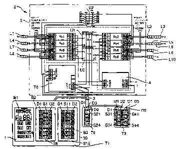
controls
of the load device may be performed. For example, in the illumination control
system,
a separate control which enables each wall side switch to control turning on
and off of
one corresponding illumination device or a plurality of illumination devices,
a group
control which controls turning on and off of one corresponding illumination
device or
a plurality of illumination devices that are divided into a group per a group,
and a
pattern control which changes the lighting pattern according to the outside
brightness
can be performed by setting arbitrarily the corresponding relationships
between each
of the operation terminals and the load control terminals.
[0003] But, it is necessary to set a load device for a target of control such
as a
separate address of the separate control, a group number of the group control,
and a
1
CA 02520310 2005-09-21
pattern number of the pattern control into each of the operation terminals in
order to
realize various controls. On the other hand, it is necessary to set the
corresponding
relationships between each of the operation terminals and the load control
terminals
such as the load device corresponding to a group 1, and the load device
corresponding
to a pattern 1 into the control unit.
[0004] Therefore, conventionally, the setting device which is required for the
setting operation is disclosed, In the Patent Reference 1, an integral setting
device of a
load control data which allows a load address setting, and a pattern/group
setting to be
performed easily and simultaneously is disclosed. Further, In the Patent
Reference 2,
a wireless switch is disclosed in which an addressable remote controller is
formed as a
shape which is same to the standardized plated so that it may be used as a
general wall
side switch.
[0005] (Patent Reference 1) Japanese Patent Laid-Open NO. 2000-115865
[0006] (Patent Reference 2) Japanese Patent Laid-Open NO. H04-233895
[0007] In all the previous technology, an infrared ray remote controller is
used for
setting the load devices into each of the operation terminals which are
arranged on an
arbitrary wall side. 'The Patent Reference 1 includes a function to set a
pattern/a group
as well as a function of an infrared ray remote controller by connecting to a
control
unit. But, the wire connection to the control unit is not described in detail,
but it is
judged that a terminal connection to a communication line drawn from the
neighborhood of the operation terminal is established. Therefore, in the
pattern/the
group setting, there is a troublesome problem that a plate of the wall side
must be
removed and a communication line has to be drawn out. Further, if the setting
is
performed, there is a shortcoming that it is not possible to manage a remote
controller
2
CA 02520310 2005-09-21
which is not used in the outside places because of the change of the room or
the
change of the seasons, and thereby it is vulnerable to the missing.
[0008] In the Patent Reference 2, a remote controller is accommodated into a
wall
side, and is used as a wall side switch by mounting it on the wall side. But,
in the
Patent Reference 2, only the fact that a remote controller is accommodated
into the
wall side is described. On the other hand, in case of this setting device, in
connection
with the operation terminal which is arranged on an arbitrary wall side of the
indoor
room, since the control unit is arranged at a remote place such as a
management room
or an electricity-division room, there was a troublesome problem that the
person had
to go to the place in order to set the parameters with a remote controller.
SUMMARY OF THE INVENTION
[0009] It is the object of the present invention to provide a setting device
of a
control system which enable the setting operations to be performed easily, and
can
prevent the missing.
[0010] A setting device of a control system according to the present
invention,
which is used for a system in which a plurality of load control terminals and
a
plurality of operation terminals are connected to a control unit via a
communication
line, and said control unit drives the load through a corresponding load
control
terminal or the plurality of load control terminals in response to the
operations of each
of the operation terminals, and which sets a corresponding relationship
between each
of the operation terminals and the load control terminals, comprises: a body
portion
including a first setting means for setting a load device which is to be a
target of
control of the operation terminal by a communication using an infrared ray
with
regard to the operation terminals arranged on a wall side, and a second
setting means
3
CA 02520310 2005-09-21
for setting a corresponding relationship between each of the operation
terminals
which are connected to said control unit via said communication line, in which
the
load device which is the target of control is set by said first setting means,
and a real
load control terminal; and a reception unit including a connection means for
connecting said body portion to said communication line under the mounting
state of
said body portion, and in which is arranged on said wall side along with at
least some
of said operation terminals, and in which said body portion is detachably
accommodated.
[0011 ] According to the above structure, in the setting device for performing
above-mentioned setting, wherein a plurality of load control terminals and a
plurality
of operation terminals are connected to a control unit via a communication
line, and
which is used for a system in which various kinds of illumination control such
as a
separate control, a group control, and an a pattern control can be realized
since said
control unit drives the load through a corresponding load control terminal, or
the
plurality of load control terminals in response to the operations of each of
the
operation terminals, and the corresponding relationships between each of the
operation terminals, and the load control terminals are set arbitrarily, a
body portion is
composed of a first setting means for setting the load device which is a
target of
control such as a separate address of the separate control, a group number of
the group
control, and a pattern number of the pattern control for the operation
terminal such as
the switches arranged on the wall side, and a second setting means for setting
a
corresponding relationship between each of the operation terminals which are
connected to said control unit via said communication line, and in which the
load
device which is the target of control is set by said first setting means, and
a real load
control terminal, and a reception unit in which said body portion is
detachably
4
CA 02520310 2005-09-21
accommodated is arranged on the wall side along with at least some of the
operation
terminals. Further, under the state that the body portion is separated from
the
reception unit, it sets the load devices which are the target of control to
the operation
terminal arranged on the arbitrary wall side such as an indoor room, or a
management
room as a format of an infrared ray remote controller by using the first
setting means.
Under the state that the body portion is mounted in the reception unit, it is
connected
to the communication line via a connection means of the reception unit, and
sets the
corresponding relationship between each of the operation terminals and the
real load
control terminal by the second setting means.
[0012] Therefore, the first setting means for setting the load devices which
are the
target of control to the operation terminal arranged on the arbitrary wall
side as a
format of an infrared ray remote controller, and the second setting means
connected to
the control unit via the communication line for setting the corresponding
relationship
between each of the operation terminals and the real load control terminal by
the
second setting means are formed integrally so that the setting operation may
be
executed easily. Further, it is possible to perform the setting of the control
unit by the
second setting means connected the communication line only by mounting the
movable body portion on the reception unit. Further, when being not used,
missing
can be prevented by mounting the body portion on the reception unit.
[0013] Further, the setting device of a control system according to the
present
invention, wherein feeding is performed via said communication line from the
control
unit under the state that said body portion is mounted on said reception unit,
and in
the state that setting is not performed, a load state outputted from said
control unit is
displayed.
CA 02520310 2005-09-21
[0014] According to the above structure, if the body portion which is
detachably
mounted on the reception unit is mounted on the reception unit, feeding is
always
performed from the control unit via the communication line, and it is possible
to
prevent the embedded battery which is used for setting the operation terminal
by
using the first setting means which is separated from the reception unit from
being
wasted. Preferably, after setting the embedded battery as a secondary battery,
charging may be performed under the state that it is mounted on the reception
unit.
[0015] Accordingly, since when setting to the control unit by the second
setting
means, feeding is performed and under the non-setting state, the operation
becomes
possible, the load state provided from the control unit is displayed. Thereby,
the
operation terminal on which the setting device is arranged, for example, only
displays
ON/OFF state of the load device, and in the setting device, various control
state can
be displayed. For example, ON/OFF state of the load device is displayed
sequentially
by using the display unit mounted for the setting operation, or the number of
devices
of ON/OFF state is displayed.
[0016] Further, in the setting device of a control system according to the
present
invention, wherein a duplex communication can be performed by an infrared ray
communication unit of said first setting means and said operation terminal, a
contents
which is already set can be read to the first setting means from the operation
terminal
before setting is performed, and in the body portion, an operation channel of
the
operation terminal is selected in response to input operation of an input
means, and
thereby, information of a load device of the channel is displayed on the
display unit.
[0017] According to the above structure, contents which are already set can be
read to the first setting means from the operation terminal by the duplex
communication of the infrared ray before setting. For example, when a
plurality of
6
CA 02520310 2005-09-21
switches are connect or mounted, in a case that the operation terminals
arranged on
the wall side can set the load devices of a plurality of channels, the setting
contents is
displayed on the display unit of the body portion by selecting a channel by a
selection
manipulation of the input means.
[0018] Therefore, even if many load devices are set for one operation
terminal, it
is possible to display the setting contents of all channels in detail.
BRIEF DESCRIPTION OF THE DRAWINGS
[0019] The above aspects and features of the present invention will be more
apparent by describing certain embodiments of the present invention with
reference to
the accompanying drawings, in which:
FIG. 1 is a block diagram showing an electrical structure of an
illumination control system provided with a setting device according to the
first
embodiment of the present invention;
FIG. 2 is a view showing of the setting device an illumination control
system of FIG. 1;
FIG. 3 is a view analytically showing the setting device of shown in FIG.
2;
FIG. 4 is view analytically showing an attachment structure for attaching
the setting device of shown in FIG. 2 to an operation terminal;
FIG. 5 is a view showing a base block for attaching the setting device to a
wall side;
FIG. 6 is a block diagram showing an electrical structure of a setting
device;
7
CA 02520310 2005-09-21
FIG. 7 is a view for explaining setting operations of a remote controller
using infrared rays;
FIG. 8 is a view showing an example for displaying a load state by using a
display unit of the setting device.
DETAILED DESCRIPTION OF THE PREFERRED EMBODIMENTS
[0020] Certain embodiments of the present invention will be described in
greater
detail with reference to the accompanying drawings.
[0021] FIG. 1 is a block diagram showing an electrical structure of an
illumination control system 2 provided with a setting device 1 according to
the first
embodiment of the present invention. In this illumination control system 2,
generally,
a terminal unit U1, U2 for controlling a plurality relays Ryl - Ry8 (8 channel
is
shown in FIG. 8), which are load control terminals, and a plurality of
operation
terminals Tl - T3 (3 terminals are shown in FIG. 3) are connected to a
transmission
unit TO which is a control device via a common communication line 3. In
response to
the operations of each operation terminal Tl - T3, the transmission unit TO
drives an
illumination device through a corresponding one relay or a plurality of
relays. Various
kinds of illumination control such as a separate control, a group control, and
a pattern
control can be realized by setting arbitrarily the corresponding relationships
between
the operation terminals T1- T3, and the relay Ryl - RyB.
[0022] The operation terminals T1- T3 are arranged on the wall side of an
indoor
room, or a management office room. On the other hand, the transmission unit
T0, the
terminal unit Ul, U2, the relay Ryl - Ry8 and a remote controller transformer
4 for
providing a power for driving the relay Ryl - Ry8 are arranged in an
electricity-
division portion 5. Further, the communication line 3 formed by a pair of
signal lines
8
CA 02520310 2005-09-21
may be connected between each of the operation terminal T1 - T3, the
transmission
unit T0, the terminal unit Ul, U2, and the relay Ryl - RyB. Each of the relays
Ryl -
Ry8 drives the illumination system Ll - L10 by turning on/off the commercial
AC
outputted from a breaker in electricity-distribution portion 5. For example, a
signal of
~24V is transmitted according to a communication format such as RS485 and so
on,
through the communication line 3.
[0023] The transmission unit TO can identify a relay by using a 8 bit address,
identify the terminal unit of 0-63 channel by using an upper 6 bit, and
identify a load
number (1- 4) by using a lower 2 bit. In the example of FIG. 1, the terminal
units are
Ul, and U2, and each of the relays (Ryl - Ry4; Ryl - Ry8) are connected to
them.
Accordingly, in the illumination control system 2 of the FIG.1, a separate
switch for a
separate control corresponding to each load channel of 8 channels is required
for the
operation terminals Tl -T3. If necessary, a group control switch, and a
pattern control
switch are arranged.
[0024] In the example of FIG. 1, the switch S1-S8 for the separate control,
and the
switch S11-S18 for a group/a pattern control are arranged on the operation
terminal
T1 (for the brevity of the drawings, some reference numbers are omitted.). For
example, if the switch S1 is operated, the relay Ryl of the load number 1 is
controlled
by the terminal unit U1 of the load channel 0, and ON/OFF of the illumination
equipments of the load device address 0-1 is controlled. Likewise, the relay
Ry2-Ry8
is controlled by the switch S2-S8, and the illumination equipments L2, L3, L4,
L5,
L6, L7, L8, L9, L10 of the load device address 0-2,0-3,0-4,1-1,1-2,1-3,1-4 are
controlled, respectively.
[0025] Further, in the example if the FIG. 1, if the switch S11-S14 is
operated,
each group control is performed in the group Gl-G4 which is formed by dividing
9
CA 02520310 2005-09-21
arbitrarily each of the relay Ryl-Ry4 as a group. Likewise, if the switch S15-
S18 is
operated, a pattern control is performed for the relay Ryl-Ry4 according to
the
predetermined pattern P-1 ~ P-4.
[0026] A LED (light emitting diode) D1 of a red color, a LED D2 of a green
color
are arranged on both sides of each of the switch S1-S8; S11-518. When the
corresponding switch is turned on, the LED Dl of a red color is lighted, and
the LED
D2 of a green color is not lighted. When the corresponding switch is turned
off, the
LED D2 of a green color is lighted, and thereby ON/OFF state is displayed. A
LED
Dl of a red color, a LED D2 of a green color are arranged on both sides of an
upper
part of the remaining switch S21-S24; S31-S34; S41-S44. A
transmission/reception
unit D3 using an infrared ray which is described later is arranged between the
LED
D1 and the LED D2 of the typical switch S21, S31, S41 of switch S21-S24; S31-
S34;
S41-S44.
[0027] In the operation terminal T2, the switch SZl-S24 is arranged and the
addresses 1-1 ~ 1-4 of the load devices corresponding to each of the relay Ry5-
Ry8
of the terminal unit U2 are set. Further, in the operation terminal T3, the
switch S31-
S34, S41-S44 is arranged, and in connection with the switch S31-S34, the
addresses
0-1 ~ 0-4 of the load devices corresponding to each of the relay Ryl-Ry4 of
the
terminal unit Ul are set. A group G-1, G-2, and a pattern P-1, P-2 are
sequentially set
in the switch S41-544.
[0028] Therefore, the setting device lis used in order to set the addresses 0-
1 ~ 0-
4, 1-1 D 1-4 of the load devices, the group G-1 ~ G-4, the pattern P-1 ~ P-4.
The
setting operation will be described briefly. In the operation terminal T2, T3,
a setting
is performed by separating the setting device 1 from the operation terminal
Tl, and
using it as a remote controller using an infrared ray. In the operation
terminal Tl, the
10
CA 02520310 2005-09-21
setting is performed under the state that the setting device 1 is attached,
and the
corresponding relationships between the switches S1-S8, S11-S18, S21-524, S31-
S34, S41-544, and the real relay Ryl-Ry8 are set.
[0029] On the other hand, in the terminal unit Ul, U2, a load channel is set
by a
dip switch of 6 bits, and the load number of the relay Ryl-Ry4; Ry5-Ry8 is
determined according to the terminal unit Ul, U2 to which the relay is
connected.
[0030] FIG. 2 is a view showing the setting device 1, and FIG. 2a is a front
view,
FIG. 2b is a view showing an upper surface side, FIG. 2c is a view showing a
right
side surface, and FIG. 2d is a view showing a rear side. Generally, in
connection with
the setting device 1, a battery reception unit 12 is formed on a body 11 of
the plate
shape so that it may be protruded. A contact point 13 is arranged in the rear
side of the
battery reception unit 12 for connecting to the communication line 3. In the
battery
reception unit 12, a battery 14 of a button shape is accommodated. On the
upper side
of the body 11, a transmission/reception unit 15 using an infrared ray is
arranged, and
a power switch KO is arranged on the side surface. A display unit 16 and
various
kinds of the operation keys (Kl-K10) are arranged.
[0031] FIG. 3 is a view analytically showing the setting device 1. The inner
structure of the setting device 1 is composed of a liquid crystal panel 21
which is the
display unit, an infrared ray module 22 which is the transmission/reception
unit 15
using an infrared ray, a terminal which is the contact point 13, and the
terminal of the
battery 14. A rubber switch 24 which is the operation switch Kl - K10 is
stacked on
the circuit board 23 on which a control circuit described later for the
setting operation
and an integrated circuit such as a memory are mounted. The above-mentioned
elements are inserted between a front cover 25 and a back cover 26. The
projection
11
CA 02520310 2005-09-21
part of the back cover 26 is opened and after the battery is accommodated, it
is closed
by the battery cover.
[0032) As is described above, FIG. 4 is a view showing the attachment
structure
for attaching the setting device 1 to an operation terminal T1. In the example
of FIG.
1, the operation terminal Tl is formed as a series of 3 specified outlet
block, and is
composed of a block B1, a block B2 of the switch S1-S8, and a block of the
switch
S11-S18. An accessory plate 30 is inserted in the outer periphery. As is
already
known, a block B2, B3 for the switch S1-S8; S11-S18, is directly fixed to a
box
embedded into a wall.
[0033] On the other hand, the setting device 1 is mounted on the base block 31
which functions as a terminal stand shown in FIG. 5. FIG. 5a is a front view
of the
base block 31, FIG. 5b is a view showing a right side, and FIG. 5c is a view
showing
a rear side. Generally, the base block 31 is formed as a boat shape, and a
screw which
is inserted into the screw holes 34, 35 of a flange formed on both ends in the
longitudinal direction is connected to a screw hole formed on the box by a
screw, and
thereby is fixed to the box by a screw. The setting device is inserted into
the base
block 31, and is absorbed by a magnet 38. A plate 36 for preventing the
falling-off is
mounted on the front side. If the setting device 1 is mounted in the base
block 31, the
contact point 13 is electrically connected to the contact point 37 of the base
block 31
side. The contact point 37 is electrically connected to the terminal stand 38
of the rear
side, and wiring of the communication line 3 is sequentially arrayed along
with same
terminal stand arranged on the block B2, B3 which are attached in same box.
[0034] FIG. 6 is a block diagram showing an electrical structure of a setting
device 1. The setting device 1 is formed by a microcomputer, and is composed
of a
processing unit 41 for performing a setting operation, a memory unit 42 for
storing
12
CA 02520310 2005-09-21
the operation program or a setting value, a signal processing unit 43
communicating
with the transmission unit TO or the block B2, B3 through the communication
line 3,
and a power source unit 44, the battery 14, the transmission/reception unit 15
using an
infrared ray, an operation unit 45 including an operation key Kl-K10 and the
power
switch K0, and the display unit 16. In the structure of the setting device 1
of FIG. 6,
the remaining structure except the signal processing unit 43 forms a first
setting
means for performing a setting described later through communication using
infrared
rays. The remaining structure except the transmission/reception unit 15 using
an
infrared ray is connected to the transmission unit TO through the
communication line,
and thereby forms a second setting means for performing a setting described
later.
[0035] If the setting device is mounted on the base block 31, and thereby,
conduction state is formed between the contact points 13, 37, AC of the
communication line 3 is derived from the signal processing unit 43, rectified
and
stabilized, and supplied to each unit from the processing unit 41. Further, if
the setting
device 1 is separated from the base block 3I, the power supplied from the
battery 14
is provided to each unit from the processing unit 41. In a case that the
current is fed
through the communication line 3 under the state that the battery 14 is set as
a
secondary battery, is it possible to charge the battery 14.
[0036] FIG. 7 is a view for explaining setting operations for the operation
terminals T2, T3. Referring to FIG.7, an example for setting a load device to
a type of
the operation terminal T2 will be explained. As is described above, in case of
setting
the operation terminal T2, T3, the setting device 1 is separated from the base
block
31, and setting is performed by a remote controller using an infrared ray. The
transmission/reception unit 15 using an infrared ray is positioned near to the
transmission/reception unit D3 using an infrared ray 15 of the operation
terminal TZ
13
CA 02520310 2005-09-21
by turning on the power switch K0, and a duplex communication is performed by
manipulating the confirmation key Kl. The setting of the present state of the
operation terminal (a block) comprising a series of switch S21-S24 is read.
Especially, in case of construction, especially, if it is not necessary to
confirm the
setting contents of the present state, the confirmation task may be omitted.
[0037] Next, a switch selection key is manipulated while confirming a switch
number display unit A1 of the display unit 16, and a switch which is a setting
target is
selected from the switch S21-S24 (In FIG. 7a, the switch S21 is selected.).
Then, one
of the setting of a separate address, the setting of a group number, and the
setting of a
pattern number is selected according to the operations of a separate key K7, a
pattern
key K9, and a group key 10 (in the operation terminal T2 of FIG. 1, a separate
key K7
of a separate address) while confirming an operation mode display unit A3 or
an
addressing display unit A2. An address 1-1 of the load device which is to be
set by an
up key K4 or a down key K5 is set while confirming the separate key of the
separate
address, and the address number display unit A4. In case of setting the
remaining
switch S22-S24, first of all, the operation of the switch selection key K3 is
repeated.
Therefore, the address of the load device 1-2 of the switch S22 shown in FIG.
7b, and
the address of the load device 1-4 of the switch S24 shown in FIG. 7c are set.
In this
way, if input of the setting is completed, as described above, the setting is
practically
performed by positioning the transmission/reception unit 15 using an infrared
ray near
to the transmission/reception unit D3 using an infrared ray of the operation
terminal
T2, and by manipulating the setting key K2. Then, the setting manipulation is
completed.
[0038] In the setting manipulation of the operation terminal Tl, first of all,
setting
of the load device number corresponding to the separate switch S1-S8, that is,
the
14
CA 02520310 2005-09-21
corresponding relays are performed. Each of the relays Ryl-Ry8 needs to be set
as a
separate switch, respectively. Setting for the separate switch (S1-S8) is not
necessary
as far as there are no changes in the load device number, that is, in the
cases except a
case of increase and decrease of the relay, and the terminal unit, or in a
case of
changing the connection between each relay and the terminal unit. Therefore,
the
setting is performed in case of construction. To be more specific, after a
setting mode
is set by manipulating the setting key K2, and a setting mode of a separate
address is
set by manipulating the separate key K7, as is described above, it may be
possible to
match a switch and an address of the load device which is to be set by the up
key K4
or the down key K5 of the switch selection key K3, or it may be possible to
set the
address of the load device from the setting device 1 by manipulating the
separate
switch S1-S8 and then selecting. In the above-mentioned setting manipulation,
the
setting is performed under the condition that the setting device 1 is mounted
on the
base block 31, and communication is possible via the block B2, B3 and the
communication line 3, but it may be possible to perform the setting by a
remote
controller using an infrared ray by arranging the transmission/reception unit
D3 using
an infrared ray in the above-mentioned block B2, B3.
[0039] Further, setting the corresponding relationships between each
group/pattern, and the real relay Ryl-Ry8 is performed by using other block
B2, B3
of the operation terminal Tl under the condition that the setting device is
mounted on
the base block 31, and it is possible to communicate with the transmission
unit TO via
the communication line 3.
[0040] That is, the pattern/group selection key K6 is operated by turning on
the
power switch K0, and a pattern/group setting mode is set. If a pattern key K9,
or a
group key k10 is operated, one of the setting of a pattern/a group, or the
setting of a
15
CA 02520310 2005-09-21
pattern number is selected. Next, the group number or the pattern number which
is set
by the up key K4 or the down key K5 is selected. Then, a switch for performing
a
group setting or a pattern setting is selected by manipulating the switch S11-
518.
Under the state, a corresponding switch of the switch S1-S8, that is, a relay
is selected
and the switch S11-518, and the switch S1-SS are matched by manipulating the
setting switch K2. In short, the corresponding relationships between each
group/pattern, and the real relay are set.
[004I] In this way, according to the setting device 1 of the present
invention, a
plurality of terminal units Ul, U2, and a plurality of the operation terminals
Tl-T3are
connected to the transmission unit TO via the communication line 3. In
response to the
operations of each of the operation terminal Tl-T3, the transmission unit TO
drives
the illumination device Ll-L10 via a corresponding relay or a plurality of
relays Ryl-
RyB. The setting device 1 is used in an illumination control system in which
various
kinds of illumination control such as a separate control, a group control, and
an a
pattern control can be implemented by setting the corresponding relationships
arbitrarily between the plurality of relays Ryl-RyB, and each of the operation
terminal
Tl-T3. In the setting device performing the setting operation, a separate
address of
the separate control, a group number of the group control, and a pattern
number of the
pattern control.
[0042] A body 1 is composed of a first setting means for performing the
setting by
a communication using an infrared ray, each switch S1-S8; S11-S18; S21-524;
S31-
534; S41-S44 which is connected to the transmission unit TO via the
communication
line 3, and to which an illumination device of a control target is set by the
first setting
means, and a second setting means for setting a corresponding relationships of
the
relay Ryl-Ry8 for substantially controlling the loads. On the body 11, the
detachable
16
CA 02520310 2005-09-21
base block 31 and the switch S1-S8; S11-S18 on the wall side are arranged in a
parallel state. Further, the illumination device Ll-L10 which is the control
target is set
to the operation terminal T2, T3 which is arranged on an arbitrary wall side
such as an
indoor room or a management room as a format of a remote controller using an
infrared ray by the first setting means. Under the mounting state, the body 11
is
connected to the communication line 3 via the terminal stand 38 from the
contact
point 37 of the base block. Therefore, corresponding relationships between
each
switch S1-S8; S11-S18; S21-S24; S31-S34; S41-S44, and the relay Ryl-Ry8 are
set.
[0043] Accordingly, it becomes possible to perform the setting task by
designing
the first setting means for setting the illumination device Ll-L10 of a
control target to
the operation terminals arranged on an arbitrary wall, and a second setting
means
which is connected to the transmission unit TO via the communication line 3
for
setting a corresponding relationships between the relay Ryl-Ry8 and each
switch S1-
S8; S11-518; S21-S24; S31-S34; S41-S44 integrally. Further, the body 11 is
connected to the communication line only by mounting the body 11 of a on the
base
block 31. Therefore, it becomes to be possible for the second setting means to
perform
the setting for the transmission unit T0. Further, when not using the body,
the loss
can be prevented by mounting the body 11 on the base block 31.
[0044] Further, in the infrared ray communication unit (15, D3) of the setting
device 1 and the operation terminal T2, T3 can perform the duplex
communication,
and before setting, the contents which are already set can be read by the
setting device
1, and in the display unit 16, the switch S21-524; S31-S34; S41-S44 of the
operation
terminal TZ, T3 is selected in response to the input manipulation of the
operation unit
45, and the information of the load devices of the switch S21-S24; S31-S34;
S41-S44
17
CA 02520310 2005-09-21
is displayed. Therefore, even if a plurality of switches is mounted, it is
possible to
display the setting contents of all switches in detail.
[0045] Under the setting device 1 is mounted on the base block 31, even when
the
operation manipulation is completed, if the power switch KO is in "ON" state,
the
feeding is continuously performed from the transmission unit TO via the
communication line 3, and the load state obtained from the transmission unit
TO is
displayed in the display unit 16.
[0046] For example, FIG. 8a shows a state of a switch S 1, and a separate
control
is displayed on the address display unit A2. An address [1] of the separate
control is
displayed on an address number display unit A4, and [o] representing the
lighting
state is displayed on a switch number display unit Al. Further, under the
state of the
switch S2 of FIG. 8b, a separate control is displayed on the address display
unit A2.
An address [2] of the separate control is displayed on an address number
display unit
A4, and [-] representing the blackout state is displayed on a switch number
display
unit A1. Further, FIG. 8c shows a state of a switch S8, and a separate control
is
displayed on the address display unit A2. An address [8] of the separate
control is
displayed on an address number display unit A4, and [o] representing the
lighting
state is displayed on a switch number display unit Al.
[0047] FIG. 8d shows a state of a switch 511, and a group control is displayed
on
the address display unit A2. A group number [1] is displayed on an address
number
display unit A4, and [-] representing the turning on or off states is
displayed on a
switch number display unit Al. FIG. 8e shows a state of a switch S18, and a
pattern
control is displayed on the address display unit A2. A pattern number [4] is
displayed
on an address number display unit A4, and [o] representing the lighting state
is
displayed on a switch number display unit Al.
18
CA 02520310 2005-09-21
[0048] In FIG. 8f, since display of the address display unit A2 is not
performed,
the switch content is not displayed. [L] representing total load (relay) is
displayed on
a switch number display unit Al, and a total load (relay) [8] is displayed on
an
address number display unit A4. Likewise, in FIG. 8g, the switch contents is
not
displayed, but [o] representing total load (relay) of ON state is displayed on
a switch
number display unit Al, and the number of load (relay) [5] is displayed on an
address
number display unit A4.
[0049] In this way, even if the operation terminal Tl provided with the
setting
device displays only ON/OFF of the switch S1-S8, S11-S18 by using the LED D1,
D2, it is possible to display various kinds of the control state on the
setting device 1.
In connection with the display of FIG. 8a - FIG. 8g, an automatic change may
be
made at every pre-set time, or the operations may performed be by manipulation
of an
up key K4 or a down key K5
[0050] The foregoing embodiment and advantages are merely exemplary and are
not to be construed as limiting the present invention. The present teaching
can be
readily applied to other types of apparatuses. Also, the description of the
embodiments of the present invention is intended to be illustrative, and not
to limit the
scope of the claims, and many alternatives, modifications, and variations will
be
apparent to those skilled in the art.
19