Note: Descriptions are shown in the official language in which they were submitted.
CA 02520410 2007-12-07
1
Adapter
The invention concerns an adapter to attach accessories, such as (night)
targeting devices,
lighting units, two-leg supports, grenade launchers or the like, to a'rearm,
specifically a rapid-
fire weapon.
It is normal in conventional weapons with a steel case to attach an adapter,
often simply termed
"telescopic sights adapter," designed to support telescopic sights for the
weapon on the steel
case. This case incorporates the gun barrel in a fixed manner. It also
includes the lock and
supports it. An exchange of the gun barrel is feasible only as part of
extensive maintenance
work.
It is normal for rapid-fire weapons with an extended outer housing of sheet
metal to attach the
adapter for mounting accessories on the outside of the outer housing of sheet
metal. The gun
barrel can be exchanged here also only as part of extensive maintenance work,
if at all. This
sheet metal housing is not always perfectly stable relative to the gun barrel
in its form and thus
its orientation under extreme conditions. This may also not be precluded
completely for modern
rapid-fire weapons with plastic housing. Nonetheless, the designer had no
option in the final
analysis but to attach the adapter or mounting unit for accessories on the
housing.
For accessories that are attaclied to the front of the weapon, such as a laser
targeting device, the
orientation of the assembly, and thus the targeting device, and thus the
achievable targeting
precision, is even more unstable, if the accessory in question is not to be
attached directly to the
front segment of the barYel. However, such an attachment to the barrel is
undesirable, at least in precision weapons, because it degrades the targeting
precision. Thus, such a unit would have to
be attached to the hand guard, the orientation of which relative to the barrel
is even less precise
than the orientation of the plastic housing.
CA 02520410 2007-12-07
2
This invention has the objective of overcoming these difficulties or to at
least ameliorate them in
part.
In one aspect, the present application provides an adapter to attach
accessories, such as night
targeting devices, lighting units, two leg-supports, grenade launchers,
shotgun accessories or the
like, to a firearm, specifically a rapid fire weapon. The adapter includes a
housing of metal
surrounding the barrel with a cylindrical exterior surface and at least one
ring formation, which
may be metallically linked to the barrel of the weapon. One ring formation is
coaxially or axis
parallel to the barrel. The adapter also includes an accessory unit for the
attachment of
accessories in a stable manner relative to the housing. The accessory unit may
contain a
formation that inserts into a matching recess of the weapon in the operating
position thus
preventing a rotation of the accessory relative to the weapon. The accessory
may be firmly fixed
to the ring formation, with an interior surface that at least in part matches
the cylindrical surface
of the housing with the characteristic that the housing is designed with a
barrel support
component in lieu of a coupling nut to support the barrel and where the
housing may be screwed
to the weapon. There are two ring formations in the form of ring grooves which
one is smaller
than the other and where the accessory unit has linkage formations that match
the smaller size.
The housing of the invention has a solid or even metallic connection with the
barrel, such that it
has the maximum rigidity in its orientation to the barrel. Temperature changes
due to sunrays
are not sufficient to modify the connection in any measurable manner.
The cylindrical exterior surface of the housing and its circumferential groove
or circumferential
grooves enable all potential rotation relative to the accessory. The accessory
is fixed in the axial
direction of the barrel by means of the ring grooves, but not in the specified
rotation direction.
In order to fix now also the rotation position, it is sufficient to insert a
formation into the body of
the weapon, thus preferably its housing. This formation may deform due to the
specified heat
influences, specifically if it is included in a plastic housing. However, such
a modification of the
CA 02520410 2007-12-07
3
formation implies merely a change in the rotation position of the accessory
relative to the axis of
the barrel, but not to the angular position. In other words, the angle between
the axis of the gun
barrel and the axis of the accessory is always constant. Normally, these axes
coincide. Whether
the target point now moves one or two tenth of a millimeter relative to the
point of incidence is
totally insignificant compared to the other confounding factors. Only the
length of the
cylindrical external surface of the housing and the matching formation of the
accessory as well
as the precision of the positioning of the accessory on the housing matter. If
these parameters
can assure that the accessory does not wobble on the housing (or does so at an
acceptable
minimal level), thus that there is no possibility for a change of the angle
between housing or the
accessory in the direction of the axis of the barrel, then the accessory is
practically fully (or
acceptably) solid relative to the barrel.
The formation may be produced later, such as by a drilled hole, or it may be
designed in a new
weapon to serve as a rotation preventer for an accessory. Preferably, an
existing formation
would be chosen.
Given that the housing is not designed to support excessive loads, it may be
produced of light
metal, such that it adds only an insignificant weight to the weapon.
The invention is primarily concerned with the improvement of a rapid-fire
weapon, whieh would
preferably be embodied as a gas pressure loader. However, the housing of the
invention may
also be attached to a machine gun, a sub-machine gun, a pistol or the like
without problems. To
the extent that the free movement of the barrel is not hindered, the
attachment to a shaipshooter
weapon may also be appropriate.
In order to facilitate a simple, but stable attachment of the accessory to the
housing, the invention
proposes that the accessory be preferably positively linkable to the ring
fornlation(s) and that it
be designed with an interior surface that matches at least in part to the
cylindrical housing
CA 02520410 2007-12-07
4
exterior surface. This would optimize the attachment of the accessory on the
housing in a
simple, but reliable manner.
The gun barrel, particularly in modem rapid-fire weapons, is held in place by
a coupling nut that
surrounds a shoulder of the barrel on its front section and that is screwed
into male threads in the
segment with the solid locking pins and which is set in the plastic housing. A
preferred
embodiment of the invention then has the housing in metal with a support for
the barrel, rather
than the coupling nut holding the barrel, that can be screwed onto the weapon.
The barrel is supported in the weapon by the housing of the invention in the
same manner as the
previously known coupling nut. Given that the housing, just as the coupling
nut, only contacts
one shoulder of the barrel, and nothing else, the barrel with the housing is
supported just as
without the housing. Thus, the housing presents no impediment to free movement
of the barrel
of a sniper weapon.
A preferred embodiment of the invention has one ring formation with a smaller
size than the
other(s), where the accessory has joining recess formations that correspond to
the smaller size.
In this case, the ring formations are circumferential grooves. Thus, the known
state of the arts
assures that locking and disengaging connectoi=s are provided for the
attachment of the accessory
in the ring formations. One is an essentially precise and solid attachment,
while the other(s)
provide for attaclunent with friction (in the direction of the axis of the
barrel) such that the
accessory may move as a result of heat expansion in a specified direction that
has no effect on
the targeting precision, in order to expand or contract relative to the
housing without restraint.
This avoids heat tension and resulting deflections that would otherwise lead
to imprecision. The
design implies here that practically all damages from heat expansion are
prevented.
However, it is also feasible to omit one of the ring forinations and instead
to provide a
protuberance or the like on the housing, which can then serve as the contact
for the accessory.
CA 02520410 2007-12-07
This protuberance may be flush against the accessory and thus transfers heat
away from the
housing. Likewise, the accessory may be designed with an enlargement of the
surface, such as ribs, in order to improve the heat transfer to the outside.
The ring formation(s) may connect with one or more recesses in the accessory.
The sleeve
diameter of the ring formation(s) is here slightly larger than the diameter of
the matching recess,
into which a pin or the like may be inserted.
Care should be taken to ensure that the accessory makes contact with such pins
on two facing or
opposite sides of the housing. Normally, a rapid-fire weapon has a front
shaft, which surrounds the barrel at least partially, and
which prevents the user from getting a burn on a hand on the hot barrel in
use. Naturally, an
accessory may also need to provide protection for the hand of the user. A
preferred embodiment
of the invention incorporates a housing of inetal inside the mounted front
shaft. In this manner, a
weapon may be set up for the possibility of a modification, without having to
undertake the
modification. In a variation, the front shaft may be designed to fit over the
housing of the
invention. This creates a weapon, where any desired accessories may be
attached after removing
the front shaft. This may apply to known rapid-fire weapons as well as to
rapid-fire weapons yet
to be designed.
In particular, the accessory may be a grenade launcher, which may be attached
underneath the
barrel and which adds high forces to the weapon, but which must always be
oriented precisely
(because the sights are elsewhere on the weapon). Thus, the grenade launcher
captures all of the
advantages of the invention. But even a bayonet (such as for a shotgun)
requires the solid
attachment provided by the invention.
CA 02520410 2007-12-07
6
However, it is particularly advantageous that the accessory be a support with
rails parallel to the
axis of the barrel, that will serve as support for accessories, targeting or
lighting units, a support,
a front "pistol grip," a belt anchor or the like.
Such rails are known and have proven to be particularly useftil in recent
years to attach lighting
units, targeting units and other apparatus to the weapon quickly and simply.
In this way, it has
become normal to load any rails present with all manner of apparatus,
regardless of their weight,
such as night vision targeting units, two-leg supports, lighting units,
specifically infrared lighting
units with high output. It is preferable that such a carrier has four rails
that are equally spaced
around the weapon at equal angles from each other, thus one rail each above,
below, and on the
two sides, relative to the axis of the barrel. This makes it feasible to
attach several units to the
carrier at the same time. The invention guarantees that the carrier can
support high loads
continuously and reliably, where these loads are directly transferred to the
element supporting
the barrel and the lock, i.e. the component best suited to accept force.
Of course, it is also possible to equip the carrier with less than four rails,
such as only a single
rail.
The carrier may consist of light metal, just as the housing. However, given
that the carrier is in
contact with a substantial extent of the cylindrical exterior surface of the
housing, which
provides strength in tuni, it has been shown to be advantageous that the
carrier consists of hard,
solid plastic. This plastic may be reinforced, such as with sprayed-on
fiberglass or it may be
Duroplast, preferably reinforced. This permits a simple, cheap and certainly
precise production
of the car-rier, regarditig the rails and also regarding the attacliment on
the housing.
The carrier may consist of two or more components, which are held together by
fasteners, such
as bolts and screws. These bolts may also project into the ring formations,
preferably riilg
grooves. However, it is optimal that the carrier is just a single piece. Then
the carrier may be
pushed over the detached gun barrel and the housing from the rear. However, it
is optimal that it
CA 02520410 2007-12-07
7
is designed to be pushed onto the housing from the front over the barrel (with
the silencer) and
(if it is a gas pressure loader) the gas transfer unit. This housing is
generally preferably
perforated, specifically to reduce weight, improve cooling and to provide bore
holes for use in
attaching and specifically in loosening the housing.
The invention is also used in a process to modify a gas pressure loader rapid-
fire weapon, which
has a barrel that can be removed by loosening a coupling nut, with an adapter
as previously
described. This process has the characteristics
- that the removable barrel may be removed by loosening the coupling nut and
is replaced
by a barrel, which has a housing in lieu of the coupling nut, where the
housing forms an
extension of the coupling nut towards the front with a cylindrical external
surface, and
- that an accessory is pushed onto the housing from the front, which makes
contact with a
formation against a matching formation on the rapid-fire weapon and that may
be axially
rotated, but that is axially essentially permanently fixed.
This process may be used in any rapid-fire weapon, regardless of its method of
operation.
If the rapid-fire weapon is a gas pressure loader with bores in the barrel to
vent the gas and with
a gas removal unit on the barrel, it is particularly advantageous that the
accessory is pushed onto
the housing over the gas removal unit mounted on the barrel. Thus the
accessory may be
exchanged without requiring that the barrel needs to be inodified or even
renioved or that the gas
removal unit must be removed first.
However, the accessory may also be separated lengthwise and may consist of two
or three
components that are mounted from the side to be linked to each other, such as
by screws.
The subject of the invention will be described in inore detail by reference to
an enibodiinent
example, that is depicted in the enclosed schematic drawing. The drawings
show:
CA 02520410 2007-12-07
8
Fig. 1 the front part of a rapid-fire weapon in a longitudinal view equipped
with an adapter in
accordance with the invention,
Fig. 2 an enlargement of the front part of the depiction of Fig. 1,
Fig. 3 the weapon of Fig. I with the same scale, in a side view,
Fig. 4 a cross section along line IV - IV in Fig. 1, and
Fig. 5 the weapon of Fig. I in a cross section, without an accessory, but with
a front shaft.
All figures show the same embodiment example of an adapter according to the
invention, but not
by way of limitation, where the adapter consists essentially of the metal
housing 9 and an
accessory 23. The scale of the figures varies. The reference numbers are
consistent in all
figures. The weapon discharges to the left in all three figures.
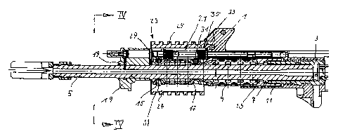
Fig. 1 and 3 show first the known parts of a rapid-fire weapon embodied as a
gas pressure loader
that are relevant here: a lock 3, made of steel, has a pipe shape, houses in
its interior the rear end
of barrel 5, is equipped with lock pins (no reference number) and is molded
into a plastic housing
1. This lock 3 is the central force-bearing component of the weapon.
Barrel 5 does not rotate within lock 3 and has a shoulder 7 that forms the
contact to this lock 3.
The lock has male threads on the outside of its free front end (part of thread
connection 11).
Housing 9 consists of steel, titanium, light metals or a combination of
various materials, and it
has a cylindrical shape. It makes contact on the front of shoulder 7 with a
protuberance 13 and
its female tllreads are firmly screwed onto the male threads of lock 3, thus
forming tliread
connection 11. To this extent, the housing 9 is equivalent to the known
coupling nut previously
used at this spot. However, it extends to contact or nearly to contact gas
removal unit 19, which
CA 02520410 2007-12-07
9
is mounted on the outside of barrel 5, but which can be removed. The contact
between shoulder
7 and protuberance 13 assures an axially parallel and essentially coaxial
orientation between the
entire cylindrical housing 9 and barrel 5.
Housing 9 has a relatively thin perforated wall and two ring grooves 15, 17: a
front ring groove
15 with slip gauge and a rear ring groove 17 with oversize. Due to the thin
housing wall, ring
grooves 15, 17 are formed by grooves in the wall.
Housing 9 surrounds barrel 5 tightly without making contact. The thread
connection 11 between
housing 9 and lock 3 likewise does not make contact with the barrel.
The axial support of housing 9 on barrel 5 is provided only by the alternating
contact of barrel
shoulder 7 and housing protuberance 13. There is no contact in a radial
direction. Thus the
barrel is free to move, and it has the same characteristics as though the
known coupling nut were
used, rather than housing 9.
Barrel 5 has a radial gas discharge bore in front of housing 9, where the bore
expands into gas
removal unit 19 in the known manner. A known arrangement 21, consisting of gas
piston, shafts
and spring, extends parallel to the barrel 5 behind the rear of gas removal
unit 19. The spring
contacts housing 1 by a shim, while the shaft extends into housing 1.
If no accessory is mounted (in the manner described) on lock 3 and thus on
housing 9 mounted
on the weapon, a known front shaft is attached to housing I in the normal
manner. However, if
accessory 23 is mounted on housing 9, the latter niay be embodied, as it is
here, as a cai-rier for
four axis-parallel rails 25, 26, 27. The accessory shown here, thus carrier
23, is designed as a
pipe-like housing made of aluminum. Other metallic materials or a plastic or a
plastic and metal
combination would also be conceivable. The bore of the accessory fits
precisely on the
cylindrical exterior of housing 9 and is pushed onto its exterior surface from
the front. The bore
CA 02520410 2007-12-07
has radial recesses 39, such that carriei- 23 may be pushed from the front
over gas removal unit
19 and the gas piston, shaft and spring arrangement 21 onto housing 9 (see
Fig. 4).
Carrier 23 has three cross bores (only one of which is designated as 37),
which tangentially
traverse ring grooves 15, 17 and which are of identical size. One bore is
placed on each of the
upper and lower (bore 37) surface of housing 9 in the area of the front ring
groove 15, while the
third bore is placed in the area of the rear ring groove 17 over the housing.
The distance between
ring grooves 15 and 17 is set such as to correspond to almost the entire
length of carrier 23.
There is a fitted pin 29 in the upper front bore, which fits exactly into ring
groove 15. The rear
bore is a loose pin 31, which has the same dimension as screw 29, which serves
as the fitted pin,
but which has play in the (larger) rear ring groove 17. Consequently, the
carrier acts as a bridge
with a solid connection 15, 29 and a loose connection 17, 31 axially, but
which may essentially
rotate in ring grooves 15, 17. An extension 35 extends beyond the rear end of
carrier 23. This
extension fits into a corresponding recess 33 of housing 1. This keeps carrier
23 from rotating on
housing 9.
As previously mentioned, carrier 23 has four rails, including the upper rail
25, two side rails 26
and an lower rai127. The other side rail can be seen in Fig. 4. An accessory
may be pushed onto
each of the rails 25, 26, 27 to be fastened there by cross grooves (no
reference riumber). The
rails as such are well known. In one enibodiment, the rails 25, 25, 27 are
Picatiniiy-rails.
The lower front bore 37 is intended for a special use, such as the addition of
accessories that
transfer significant force to the weapon.
When the adapter according to the invention is used, the housing 9 may be
screwed tightly onto
lock 3 using the thread coruiection 11, regardless of the final rotational
position. After all,
accessory 23 is bound to housing 9 only axially. The rotational lock is
handled by the pair of
CA 02520410 2007-12-07
11
matching formations 33, 35. Here recess 33 is designed from the start in the
production of the
weapon.
Fig. 2 shows specifically that the loose connection (loose pin 31, ring groove
17) is designed to
have not a circular, but extended oval groove 17. Fig. 2 also shows that
housing 9 and accessory 23 do not make contact with gas removal unit 19.
The solid connection of the latter is thus not degraded in any fashion by the
adapter according to
the invention.
It is also feasible to add a separate hand protector in the lower rail 27 or
behind the carrier 23
itself.
Fig. 4 shows a cross section through the weapon designated as IV - IV in Fig.
1. The single-
piece carrier 23 can be seen here, which sits on housing 9 with a bore. The
bore has recesses 39,
such that the carrier 23 may be pushed over gas removal unit 19 during
assembly or disassembly.
If accessory 23 is removed, a front shaft 41 may be added (Fig. 5), which is
not obstructed by
metal housing 9 in any manner.