Note: Descriptions are shown in the official language in which they were submitted.
CA 02520534 2008-04-29
1
Molding Device
The present invention relates to molding devices, and in particular, molding
devices for
production of containers.
.Processes and molding devices for production of containers are known in the
prior art
(DE 199 26 329 A 1), ones in which a hose of plasticized plastic material is
extruded into a
molding mechanism, one end of the hose is closed by heat sealing and the hose
is expanded by
generation of a pn-.umatic pressure gradient acting on the hose and applied to
the molding wall
of the molding mechanism consisting of two opposite molding tools to form the
container. The
plastic container iii then filled under sterile conditions into the molding
mechanism by way of an
appropriate charging mandrel and, after the charging mandrel has been removed,
is hermetically
sealed, a specific head geometry being formed. For the purpose of forming the
plastic container
proper, in which fluid is later stored, two container molding jaws may be
moved toward each
other by hydraulic drive means in order to obtain a closing position and away
from each other
into one of their o iening positions.
The head geometries to be generated by the two separately actuatable head jaws
regularly
also comprise the neck component of the plastic container, including one in
the form of ampules,
which, closed by it head piece by way of a separation point, may be opened for
a fluid removal
process as soon as the head piece is separated by way of a separation point
from a toggle piece
molded on it and in this way removed from the plastic container proper.
CA 02520534 2008-04-29
2
Such processes have been disclosed in a plurality of embodiments and are
widely used in
packing systems for liquid or paste products, for example, in the disclosed
bottelpack7 system.
The hydraulic drive systems regularly employed in practical applications for
the
respective feed movement of the molding tool present problems in that any
leakage may result in
fouling with the fluid, something which results in problems especially when
the molding
machines are used for plastic containers in the pharmaceutical and food
packaging spheres and in
medical technology in general. The maintenance cost is also increased and the
hydraulic drive
systems do not reach the desired or high cycle frequencies for mass production
for the sake of
precise positioning of the molding tools for shaping of containers.
On the basis of this prior art an object of the invention is to create a
molding device for
moving at least one molding tool, a tool making it possible to apply modem
drive concepts, such
as ones in the forn i of electric or pneumatic drives, the maintenance cost of
which is reduced and
which permit especially high rates of output of goods to be produced, such as
plastic containers,
along with high positioning accuracy for the molding tools.
In the molding device of the invention a link motion control element is
provided
for moving at leas: one molding tool, especially one for generation of
container geometries in
plastic containers; this element moves the respective molding tool to a
closing position at least
for closing the mold, the link motion control element being actuatable by a
drive. On the basis of
the link motion control element a novel drive and movement concept is
presented for the
respective molding tool, one which makes it possible to dispense with
hydraulic drive means
entirely and by preference to employ an electric or pneumatic drive as the
drive means. The link
motion control element in question may, however, continue to be actuated
conventionally by
CA 02520534 2008-04-29
3
means of a hydraulic drive if the respective application appears to call for
it and rigid
requirements have not been set for sterile filling or clean room qualities.
The molding device of the invention with drivable link motion control element
for a closing movement with the molding device permits uniform, safe, and
position-accurate
driving of the respective molding tool and entails only a minor maintenance
effort. The link
motion control element maybe employed to execute a plurality of opening and
closing processes
in rapid sequence; with the molding device claimed for the invention this
results in high output
of goods to be produced, in particular those in the form of blow-molded
plastic containers filled
under sterile conditions.
In one preferred embodiment of the device of the invention the link motion
control element has a slot guide positioned on the exterior circumference on a
body of rotation
actuatable by a drive. By preference provision is also made such that there is
engaged in the slot
guide an actuating member which operates in conjunction with a slide component
and such that,
during rotation of he slot guide from one of its end positions to its other
end position and vice
versa, the slide component with molding tool which may be associated with it
may be displaced
with the molding tool by way of the. actuating member which my be moved
longitudinally in this
manner from a clo sing position to an opening position of the mold shaped by
the respective
molding tool and vice versa. Safe and precise positioning control is achieved
as a result, along
with clearly defined specific closing forces specified by the link motion
control element.
In another especially preferred embodiment of the molding device of the
invention, the maximum closing force for the molding tool may be specified by
way of.central
adjusting means on the slide component means preferably in the form of an
energy accumulator.
Pressure spring ek ments, such as ones in the form of disk springs or the
like, are suitable for use
as energy accumulators. -Independently of the closing force of the link motion
control element
CA 02520534 2008-04-29
4
which is applied, this force may be appreciably limited, and the reliability
of shaping thereby
increased, by way of the adjusting means. It has been found in configuration
of the molding
device to be especially cost-effective to mount the body of rotation together
with the drive so as
to be stationary on a machine frame in relation to which the slide component
may move back and
forth along its rail guide. A rigid machine configuration is achieved for the
slide component and
for the molding device as a whole and obstacles in operation are reliably
eliminated on the basis
of the rail guide in question.
In another especially preferred embodiment of the molding device of the
invention, the molding tools mounted opposite each other may be moved by a
single link motion
control element sychronously by way of a common driving component. By
preference
provision is also rr.ade such that at least four link motion control elements.
positioned in pairs,
one opposite the cther, may be driven by gearing actuatable by the drive and
the common drive
component. As a result, a total of four molding tools with mold geometries
mounted in sequence
may be actuated in pairs operating together synchronously for shaping and mold
opening
processes in order to produce several container geometries.
In one pref.: rred embodiment provision is also made as protection from
collision such
that a monitoring Fssembly monitors the position of the link motion control
element, at least with
respect to the position of the molding tool in its closing position, but
preferably also in its
opening position:
It has also been found to be favorable for obstacle-free operation in one
preferred
embodiment of the molding device claimed for the invention for the path
equation for the slot
guide of the body of rotation to be executed as a Bestehorn sinoid.
CA 02520534 2008-04-29
According to an aspect of the present invention there is provided a molding
device, comprising:
a first molding tool;
a link motion control element coupled to and moving said molding tool between
an
opening position and a closing position, said link motion control element
having a
rotation body with a slot guide on an external circumferential side thereof,
having an
actuating member engaged by said slot guide and having a slide component
operable in
conjunction with said actuating member, rotation of said slot guide from one
end area to
another end area and vice versa displacing said slide component and said
molding tool by
longitudinal displacement of said actuating member between said opening and
closing
positions of said molding tool;
a drive coupled to and actuating said rotation body.; and
adjusting means on said slide component for varying a maximum closing force of
said
molding tool.
According to another aspect of the present invention there is provided a
molding
device, comprising:
first and second molding tools mounted opposite one another as a first pair;
third and fourth molding tools mounted opposite one another as a second pair;
first and second link motion control elements coupled to and moving said first
and
second molding tools, respectively, opposite each other as said first pair
synchronously
between opening positions and closing positions;
third and fourth link motion control elements coupled to and moving said third
and
fourth molding tools, respectively, opposite each other as said second pair
synchronously
between opening positions and closing positions;
a drive and a common drive component coupled to and actuating by gearing said
link
motion control element.
According to a further aspect of the invention there is provided a molding
device,
comprising:
a first molding tool;
a link motion control element coupled to and moving said molding tool between
an
opening position and a closing position, said link motion control element
having a
CA 02520534 2008-04-29
5a
rotation body with a slot guide on an external circumferential side thereof,
said guide slot
extending along a path defined by a Bestehorn sinoid; and
a drive coupled to and actuating said rotation body.
The device claimed for the invention will be described in detail below with
reference to
an exemplary embodiment illustrated in the drawing, in which not drawn to
scale
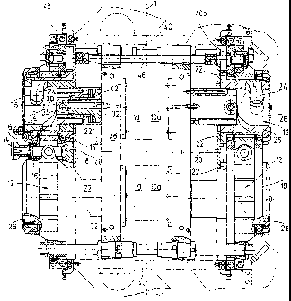
FIG. 1 pre, ents a top view of the molding device as a whole;
FIG. 2 an enlarged section of FIG. 1 representing the upper left segment of
the latter;
FIG. 3 the development of the path geometry of a link motion control element
mounted
on f. body of rotation and having slot guides such as the path geometry
applied in
the molding device shown in FIGS. I and 2.
First a part of the molding device as a whole for moving a molding tool 10
will be
described with reference to the upper left segment of the illustration in FIG.
I and FIG. 2. On its
free front side the molding tool 10 has trough-like recesses (not shown) which
form mold halves
for generation of container geometries for plastic containers (not shown),
including ones in the
form of ampules. For the purpose of generating the respective container
geometries the molding
tool 10 operates in conjunction with a corresponding molding tool IOa with
correspondingly
shaped recesses (not shown), the two molding tools 10,10a being in the closed
molding position
shown in FIG. 1, in which position the free front surfaces of the molding
tools 10, 10a meet
along a closing separation line I - I.
For the purpose of moving the respective molding tool 10, 10a use is made of a
link
motion control element designated as a whole as 12 which may be driven by
means of a centrally
mounted drive 14. For the sake of simplicity there is shown in FIG. 1 only the
spline shaft of the
drive which may be coupled to the driven shaft of an electric motor, such as
one in the form of
CA 02520534 2005-09-27
WO 2004/091892 PCT/EP2004/000531
6
an electric stepping motor, and permits driving of the link motion control
element 12. For this
purpose the spline ;haft 14 is rotatably mounted by way of bearings 16 in a
machine frame 18
and has a drive gear 20 on its one free side facing the molding tool 10. The
drive gear 20 in
question meshes with a driven gear 22 of the link motion control element 12.
The link motion
control element 12 has a slot guide 24 which is positioned on the external
circumference side on
a body of rotation 26 which may be powered by drive 14 and which is
essentially cylindrical in
configuration. The respective slot guide 24 has two path or curve segments 28
resulting from
development of the body of rotation 26 as show in FIG. 3. The respective path
curve of a curve
segment 28 obeys a path equation for a Bestehorn sinoid. The respective body
of rotation 26
with its path curve segments 28 need not be configured to be identical for the
molding tool 10a to
the body of rotation 26 for the molding tool 10. In this instance slight
adaptations maybe
necessary with respect to the control curve pattern. However, the bodies of
rotation 26 of the
two mold halves 10, 1 Oa are in other respects essentially the same.
An actuating member 30 in the form of a cam follower engages the slot guide 24
with its
two path curve segments 28. The actuating member 30 in question is mounted
rotatably on
opposite sides of a slide component 32 so that, as the body of rotation 26
with its slot guide 24
rotates, uniform advance in the direction of closing of the molding tools 10,
10a is ensured, along
with uniform reseti ing movement into a corresponding opening position, the
respective rearward
position being indi;ated by a broken-line circle at the top left in FIG. 1 and
in FIG. 2. When the
slot guide 24 rotate s from one of its end areas 34 to the other end area 36
of a path curve segment
28, the slide component 32 may be displaced longitudinally in one direction of
movement and in
the other direction when the body of rotation rotates in the opposite
direction. Consequently, the
maximum path of i ravel which may be reached for the slide component 32 thus
is determined by
the longitudinal axial distance between the end areas 34, 36 opposite each
other of two different
path curve segments 28 of a slot guide 24 of a body of rotation 26.
CA 02520534 2005-09-27
WO 2004/091892 PCT/EP2004/000531
7
The slide component 32 has on its frontal side facing the molding tool 10 a
guide
component 38 on which the respective molding tool 20 may be mounted so as to
be replaceable
and on the edge sic.e the guide component 38 is mounted so that it may be
displaced axially in
the longitudinal direction along two rail guides 40, the ends of the rail
guides,40 being
appropriately mounted in the machine frame 18. In addition, the guide
component 38 is retained
so that it may be displaced longitudinally in a displacement component 42 of
the slide
component in a dir -Iction in parallel with the rail guides 40, the
displacement component 42
resting on adjusting means 44 in the form of a disk spring package which
functions as a
compression spring. In this way the maximum closing force for the molding tool
10 may be
determined by way of the adjusting means 44 so that a reliably operating
shaping process is
made possible.
In the line cif sight to FIG. I a drive component 46 in the form of a drive
shaft is mounted
at the top in parallel with the upper rail guide 40. At both ends of the drive
shaft 46 a crown gear
48, 48a is connected to this shaft, so that, as the body of rotation 26 moves
by way of the drive
shaft 14, the driven. gear 22 meshes with the crown gear 48, thereby driving
the drive shaft 46,
which in turn trans nits the driving power by way of the crown gear 48a on the
opposite side to
the following driven gear 22 of the body of rotation 26 following in the drive
chain.
Consequently, the molding tools 10, lda mounted opposite each other may be
actuated and
moved in pairs by Ii single link motion control element 12 with drive 14, by
way of the common
drive component 46. Hence, molding tools 10, 10a move synchronously into their
opening
position and into tY eir closing position along the closing separation line I -
I.
As is also to be seen in the illustration in FIG. 1, four link motion control
elements 12
positioned opposite: each other in pairs may thus be actuated in the drive
direction appropriate for
back-and-forth movement of the slide components 32 of the molding device by
way of the gears
operated by the dri-,re 14 and consisting of gears 20, 22 and 48, 48a. The
respective drive is very
CA 02520534 2005-09-27
WO 2004/091892 PCTIEP2004/000531
8
accurate and permits precise positioning of the respective molding tool 10, 1
Oa for a molding
process. In addition, the molding tools 10 opposite each other in one line may
be connected to
each other on one side, but may also be separated from each other, that which
has been stated
also applying correspondingly to molding tools 1Oa mounted opposite each
other.
As is also to be seen in FIG. 2, a monitoring assembly 50 is provided. It is
spring-loaded
and may be displaced longitudinally from its locking position illustrated in
FIG. 2 into a release
position, preferably from the exterior by way of an actuator, in particular
one in the form of a
pneumatic cylinder or the like. The body of rotation 26 accordingly has on the
external
circumference side a first recess 52 which corresponds to the closing position
of the molding
tools 10, 10a. If lo,,king occurs in this locking position, that is, if parts
of the monitoring
assembly 50 are engaged in the associated recess 52 in the body of rotation
26, it is made certain
that a locking posit on has been assumed along the closing separation line I -
I by the molding
tools 10, 1 Oa and tr.at the machine control unit then recognizes that a
reliable molding process is
possible. If as a re,.ult of an error the position in question is not assumed,
the monitoring
assembly 50 ascertains this and the molding process could be halted without
damage to the
molding device. The reset opening position area for the molding tools 10, lOa
may also be
monitored synchronously by way of the monitoring assembly 50, by means of a
recess (not
shown) positioned diametrically opposite recess 52. In addition, the drive
shaft 46 is mounted on
the end side so as to be rotatable, by way of additional bearings 54 in the
machine frame 18.
The configuration of the molding device as described makes it possible to
reach very high
cycle speeds in production of molded containers of a plastic material, along
with very high
machining accuracy, in view of the specifiable accuracy of positioning of the
molding tools 10,
I Oa, with respect both to their closing position and to movement apart into
their opening position
for the production mold. The molding device is very rigidly configured from
the viewpoint of its
structural design, so that precise actuation of the moving parts is ensured,
while the molding
CA 02520534 2005-09-27
WO 2004/091892 PCT/EP2004/000531
9
device may be very cost-effectively produced and maintained because of the
equivalent parts
employed.