Note: Descriptions are shown in the official language in which they were submitted.
CA 02520547 2005-09-27
Sedimentation basin
The invention relates to a sedimentation basin for a two-phase suspension,
particularly for
sewage sludge, in which the denser and therefore heavier phase settles
downwards by
gravitational separation, resulting in the formation of a separation level
between the heavy
phase and the light phase.
Nowadays gravitational sedimentation basins are used worldwide as standard
constructions
for solidlfluid separation in biological purification stages of sewage
treatment works. Despite
decades of research work in this field, these constructions do not function in
an optimal
manner. Their separation performance is unsatisfactory in relation to the
space which is
available to them for this purpose. Also the discharge values of the lighter
phase which is to
be clarif ed are frequently unsatisfactory. This is the case in particular
when the inlet lies
above the separation level. The separation level is defined as the level from
which the
concentration in the sedimentation basin rises with a high gradient from the
residue of the
lighter phase to the heavier phase. The discharge value or discharge quality
is defined as the
residual quantity of heavy phase to be separated off in the discharge of the
light phase to be
clarified or vice versa. Because of the known problems with sedimentation
basins there are
numerous publications which deal with optimisation of these constructions.
They contain
repeated references to the dominant influence of the inlet construction.
According to the laws of physics of dense flows, dense flows suck in fluid
from the ambience
over their edges. The extent to which this sucking in takes place is directly
dependent upon
how high the total energy is which the flow has at its entry into the ambient
fluid. This
sucking in of ambient fluid which increases the transported volume flow and
mass flow in the
dense flow is called entrainment. A volume flow Q grows by entrainment on its
flow path
from the inlet volume flow Q; to an increased volume flaw Q = Q; + ~Q. Since
sedimentation basins fulfil their function all the more efficiently the
smaller Q is, any
measure which reduces the energy of the inflowing suspension at the inlet
increases the
efficiency of the sedimentation basin.
CA 02520547 2005-09-27
2
The entrainraent behaviour of a dense flow can be influenced technically only
over a limited
area, the so-called near field of the technical construction; in the far field
of the construction
the entrainment is produced from the locally prevailing physical parameters of
density
difference between the local density p; and the density of the ambience pa,
the local pressure
gradient, the thickness hp of the dense flow and consequently its local
velocity.
The total energy present at the inlet can be written as the sum of its
individual components:
Ftot = (~k~min + Eb + epic + DEU
The inlet area A; of an inlet construction which is flowed through
horizontally can be
calculated at A; = h; ~ b; in case that the height h; of the inlet cross-
section remains constant
over the inlet width b;. The volume flow per inlet width is q; = Q;Ib;, the
average inlet
velocity is U; = q;/h;.
If the local energy F.~a = (EPx)<";n + AE is higher by an energy surplus DE =
Eb + ~k + AEU
than the minimum necessary energy (F.~,k)mi~ in order to move a dense flow
with a given
volume flow Q, this leads to entrainment. According to the physical least-
energy principle,
for sedimentation basins (F.p~m;a is established when the densimetric Froude
number is FrD-=- -
U;I(g' ~ h;)~a = 1 with simultaneously the widest possible inlet and the inlet
lies at the
separation level. The gravitation constant g' which is actually effective
locally results from
the difference between the local density p; and the density of the ambience pa
as g' = (p; - p~/
p8 ~ g.
Ed is the amount by which the energy surplus OE at the inlet increases if the
inflow does not
take place at the height of the separation level.
If a suspension of density ps is introduced below the separation level
situated at the height hs
at a vertical distance ha from the point of equal density of the ambient phase
into an ambient
phase of higher density, because of its lower density it has a buoyancy energy
En and is
consequently deflected upwards from the horizontal at the angle ~. The deeper
the
introduction is below the separation level the greater therefore is the
buoyancy energy Eb and
CA 02520547 2005-09-27
3
consequently the rate of entrainment. From the energy point of view these
considerations
give rise to the requirement to configure the inlet into a sedimentation basin
so that the lifting
energy for fluctuating heights hs of the separation level is minimised by
adaptation of the
relative height ho of the inlet surface just below the separation level with
ho ~ 0 and thus Eb
0.
~,k is the amount by which the energy surplus DE at the inlet increases if the
optimal
relationship of kinetic and potential energy with FrD = 1 is not present. The
inlet height h;
which is optimal in energy terms is ha = (qi2~g,)lr~ with Frd = 1. Thus for
variable inlet
conditions the Froude number can be controlled by adaptation of the height h;
of the inlet.
~Eu is the amount by which the energy surplus DE at the inlet increases if the
width b; of the
inlet is smaller than the maximum possible width. By geometric consideration
the maximum
possible width is produced with the technical feature of an inlet disposed
around the
periphery.
The entrainment can have a positive effect on the discharge values of a
sedimentation basin
when it ensures at the inlet of the suspension that the incoming suspension is
to a limited
extent enriched with suspension of a higher density from the sedimentation
basin and thus the
larger flocks of the ambient suspension can hold back smaller particles of the
intake
suspension and thus a so-called flock filter effect takes place. This Flock
filter effect is a
desirable process which is demanded for example in dimensioning rules for
secondary
sedimentation basins.
Flows in sedimentation basins may be distinguished according to their flow
direction as
source or sink flows. In source flows the fluid is continuously retarded on
the flow path by
constantly increasing pressure, and in sink flows the fluid is continuously
accelerated by
constantly falling pressure. A sink flow travels in a substantially more
stable fashion and
consequently is markedly less susceptible to disturbances. Disturbances are
caused in
sedimentation basins by flow rates U; at the inlet which vary over time. These
disturbances
impose pulse forces on the stratified fluid body which axe proportional to the
rate U;. In the
case of a central inlet U; is very great and the resulting great destabilising
disturbances are
CA 02520547 2005-09-27
4
superimposed on a flow which is in any case unstable. In the case of a
peripheral inlet the
rate U; is markedly less and thus the pulse force is drastically reduced and
moreover is
superimposed uncritically on a stable flow.
The phenomenon that the entrainment decreases as ha becomes less and therefore
the
buoyancy energy F,s becomes less is utilised in the method described in the
patent DE 197 58
360 C2 and the corresponding publication EP 0 923 971 A1 in which !ta is
minimised in
stages at a central inlet construction for round sedimentation basins. A
minimisation of ~,k
and 4EU is not considered here. Thus the entrainment phenomenon can be
reduced, but
remains present to a significant extent. However, adaptation of the height lea
of the inlet in
stages is seen as very critical for a central inlet construction, since when a
stage is started and
taken out of operation the adaptation imposes very discontinuous flow rates
and thus
particularly destabilising pulses on a source flow which is physically
unstable in any case.
This leads potentially to markedly poorer discharge qualities.
The phenomenon that the entrainment decreases as b; becomes greater and thus
the energy
~Eu becomes less is utilised for example in the method described in the
publication DE
198 30 311 A1, in which the inlet is disposed peripherally, thaE is to say at
the edge of the
sedimentation basin, near the floor. A minimisation of ~k is not considered
here and Ee is
actually maximised by placing the inlet near the floor. Thus the disturbing
effect of the
entrainment is also retained to a large extent in this case.
Patent Abstracts of Japan Vol. 008 No. 077 (C-218), i.e. JP 59 004 407 A, and
Patent
Abstracts of Japan Vol. 2000 No. 14, i.e. JP 2000 325706 A, disclose a
variable inlet
construction for a sedimentation basin which makes it possible that for all
layers of the
separation level within the sedimentation basin the upper edge of the inlet
lies as high as
possible but always below the separation level. However, no suitable
structural measures are
provided which force the incoming volume flow into a horizontal flow
direction. Rather, the
incoming suspension flows through a vertical cylinder which is adjustable in
height in a
predominantly vertical flow direction past the height-adjustable lower edge of
the inlet
cylinder into a greater depth. The actual level of the taming point at which
the vertically
downwardly directed flow of the suspension becomes a horizontal flow
direction, and thus
CA 02520547 2005-09-27
the inlet height which determines the resulting lifting energy, is not
controlled technically in
these previously known inlet constructions. There is no defined inlet surface
for the
horizontal inlet flow. In this previously known constructions the actual level
of the transition
between vertical and horizontal flow direction is produced according to
physical laws
exclusively as a function of the balance of a downwardly directed pulse force
by flow
velocity on the one hand, and an upwardly directed buoyancy force which the
downwardly
flowing inlet jet is subjected to by ever increasing ambient density.
In view of the described disadvantages in the prior art, the technical problem
is posed of
proposing an optimised sedimentation basin which is distinguished by higher
separation
performance, better discharge plant, lower internal loading and operation with
little
disturbance.
The present invention is based on the recognition that not only destabilising
pulses but also
the inlet energy
F.~ _ (E~",;" + Eb + ~Epk + tlEU
must be decreased as far as possible at the inlet or must be reduced to the
technically possible
minimum. Thus the entrainment which is dependent upon the inlet energy is also
reduced
with the highest possible stability of the flow.
In a sedimentation basin with a centrally disposed inlet construction with at
least one
suspension supply line and at least one inlet which is adjustable in height
and opens into the
sedimentation basin in the region of the separation level, this object is
achieved according to
Claim 1 in that the inlet has an inlet cross-section which is flowed through
substantially
horizontally and of which the relative height ho can be adapted continuously
to the respective
height 1~ of the separation level. By the provision of an inlet surface which
is flowed through
horizontally with a defined upper and lower edge it is possible to adjust the
effective height
of the inlet flow for each operational state so that the input of energy at
the inlet is minimal.
CA 02520547 2005-09-27
6
The object is also achieved by a sedimentation basin in which according to
Claim 7 the inlet
is disposed at the edge of the sedimentation basin and the relative height ha
of the inlet can be
adapted to the respective height hs of the separation level.
If in a central inlet construction the adaptation of the relative height ho of
the incoming flow
to the respective height hs of the separation level takes place continuously,
then the critical
destabilising change of pulse is minimised thereby. If the minimisation of the
relative height
ho is combined with a peripheral introduction, then because of the maximised
inlet width b;
with simultaneously optimised inlet height h;, surprisingly no further
entrainment into the
inlet jet takes place. Thus in this case this results in a reduced volume flow
in the main flow,
so that the loading of the basin decreases, instead of increasing due to
entrainment.
Consequently the sedimentation basin can be of smaller construction or, in the
case of
predetermined size, can be more highly loaded.
Advantageous embodiments of the invention are set out in the subordinate
claims.
If not only the relative height h4 of the inlet but also the height h; of the
effective inlet cross-
section can be varied, then depending upon the volume flow and/or density of
the introduced
suspension a destabilising change in pulse in the region of the inlet can be
prevented even
more effectively.
A particularly advantageous construction of a peripheral inlet which can be
adjusted in height
is provided if the wall of the basin is broken by slots running all or part of
the way around at
at least two levels and the inlet is controlled by means of closure devices so
as to be
adjustable in height in stages.
A further advantageous construction of a peripheral inlet which is adjustable
in height is
produced if at least two pipes which run all or part of the way around are
disposed one above
the other on the periphery of the basin, and feeding thereof can be
distributed completely or
partially to individual pipes using control and regulating techniques. The
pipes must be
capable of being flushed or scraped so that the suspension can be completely
discharged in
pipes which are temporarily not being supplied Otherwise, for example in the
case of
CA 02520547 2005-09-27
7
biochemically active suspensions such as those flowing into secondary
sedimentation basins,
disadvantageous decomposition processes take place if the suspension remains
for a long
time in the inactive pipe.
The entrainment out of higher-density regions which has a positive effect on
the flock filter
action can be encouraged by means of a flow deflector above the inlet to
ensure that
entrainment into the incoming suspension flow can be supplied exclusively from
the lower
region of the sedimentation basin with suspension of a higher density. By
means of an
inclination of the f<ow deflector it is possible to limit the angle ~ at which
the dense flow
moves upwards. The entrainment is also controlled in this way. If one or more
flow
deflectors are constructed so that their angle ~ can be varied in operation,
it is possible to
control the entrainment variably for several static inlet heights and to guide
the incoming
dense flow in a controlled manner to the separation level.
Since the geometric shape of the surface has no qualitative influence on the
physical
phenomena which are relevant for the invention, it is possible for the surface
of the
sedimentation basin to be constructed in a round or rectangular shape. Special
shapes of the
basin surface are also possible.
Since the form of the extraction of the lighter phase has no qualitative
influence on the
phenomena which are relevant for the invention, the extraction of the lighter
phase can take
place in the form of weirs, open or immersed discharge pipes or other means.
Since the form of the extraction of the heavier phase also has no qualitative
influence on the
phenomena which are relevant for the invention, the extraction of the heavier
phase can take
place gravitationally with or without assistance from scrapers, with an
inclined or horizontal
floor of the sedimentation basin, by suction or by other means.
For reasons of construction and geometry it is possible that the separation
level falls below
the inlet surface at times in the case of very low loading of the
sedimentation basin for an
inlet height at the lowest adjustable point.
CA 02520547 2005-09-27
Embodiments of the invention are described in greater detail below with
reference to the
appended drawings, in which:
Figures la - lc show a round sedimentation basin with a central inlet
construction, in its
height adjustable inlet pipe and adjustable deflector plate;
Figure 1d shows a rectangular sedimentation basin with a central inlet
construction, a
partition which is adjustable in height and adjustable deflector plate;
Figures 2a - 2c show a round sedimentation basin with a central inlet
construction, inlet pipe
and telescopic pipe ring;
Figures 3a - 3c show a round sedimentation basin with peripherally disposed
intake basin,
partition and telescopic boundary wall;
Figure 3d shows a rectangular sedimentation basin with peripherally disposed
intake basin,
partition and telescopic boundary wall;
Figures 4a, 4b show a round sedimentation basin with peripherally disposed
inlet conduit
which is adjustable in height;
Figures 4c, 4d show a round sedimentation basin with centrally disposed inlet
conduit which
is adjustable in height;
Figure 4e shows a rectangular sedimentation basin with inlet conduit which is
adjustable in
height disposed at the edge;
Figures 5a - Sc show a round sedimentation basin with intake basin disposed at
the edge and
partition having slots;
Figure 5d shows a rectangular sedimentation basin with intake basin disposed
at the edge and
partition having slots;
CA 02520547 2005-09-27
9
Figures ba - be show a round sedimentation basin with central inlet
construction, telescopic
inlet pipe and deflector plate which is adjustable in height;
Figure 6d shows a rectangular sedimentation basin with intake basin disposed
at the edge,
telescopic partition and deflector plate;
Figures ?a, 7b show a round sedimentation basin with two inlet conduits
disposed one above
the other at its edge;
Figure 7c shows a rectangular sedimentation basin with two inlet conduits
disposed one
above the other at its edge.
A!1 the drawings show sedimentation basins in highly simplified vertical
sections. Similar
elements are in each case denoted by the same reference numerals.
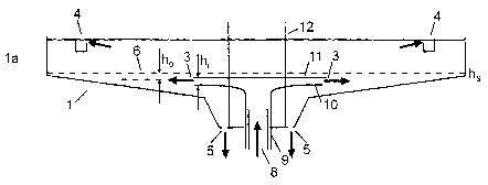
The round sedimentation basin which is shown by way of example in Figures la
to 1c has a
central inlet construction with an inlet 3 for a suspension of sewage sludge
and water. The
heavier sludge settles downwards, whilst clear water is in the upper part of
the sedimentation
basin 1. The clarified water is drawn off from the surface by a clear water
extractor 4. The
sludge which has settled downwards is drawn off at the deepest point of the
sedimentation
basin 1 by a sludge extractor 5. Between the heavy phase, that is to say the
sludge, and the
light phase, that is to say the clear water, a separation level 6 is formed. A
flow deflector 7
mounted above the inlet 3 prevents entrainment from above.
The relative height ha of the inlet 3 is defined by the distance from the
separation level 6.
The cross-section of the inlet 3 has the height h;. The suspension flows
thmugh the inlet 3 in
a predonunantly horizontal direction.
A suspension supply line 8 passes through the base of the sedimentation basin
1 and merges
into a vertical intake pipe 9. The upper end of the intake pipe 9 merges
constantly into a
horizontal inlet surface 10. The intake pipe 9 is of telescopic construction,
so that the height
CA 02520547 2005-09-27
ho of the inlet can be continuously altered relative to the separation level
6. A deflector plate
11 is disposed above the inlet surface 10, parallel thereto and spaced
therefrom. The
deflector plate 11 can be moved upwards or downwards in the vertical direction
by means of
lifting rods 12. In this way the height h; of the inlet cross-section can be
changed as a
function of the volume flow and/or the density of the introduced suspension.
In the rectangular sedimentation basin shown in Figure 1d the inlet 3 is
disposed on the left-
hand edge. The suspension supply line 8 merges into an intake basin 13 which
extends along
the left-hand edge of the sedimentation basin 2. A partition 14 is disposed
between the intake
basin 13 and the sedimentation basin 2. The partition 14 merges at its upper
edge into a
horizontal inlet surface 10. A deflector plate 11 is disposed above the inlet
surface 10,
parallel thereto and at an adjustable distance therefrom. The distance between
the inlet
surface 10 and the underside of the deflector plate 11 defines the height h;
of the inlet cross-
section. The partition 14 is designed to be adjustable in height, so that a
continuous
adaptation of the relative height ho of the inlet 3 to the respecrive height
hs of the separation
level 6 is achieved.
In the operational state illustrated in )~igure la the separation level 6 is
relatively low down.
The height ho of the inlet 3 is set correspondingly low. Furthermore in this
operational state
the inlet cross-section is kept relatively small due to the fact that the
distance between the
inlet surface 10 and the deflector plate 11 is relative small, resulting in a
comparatively small
height h; of the inlet cross-section. By contrast, in Figure 1b the separation
level 6 is
substantially higher. The height ho of the inlet 3 has been brought
correspondingly upwards,
so that the inlet 3 lies just below the height hs of the separation level.
Also the height h; of
the inlet cross-section has been raised as the distance between the inlet
surface 10 and the
deflector plate 11 is increased.
The round sedimentation basin illustrated in Figures 2a to 2c has a centrally
disposed inlet
construction, comprising a suspension supply line 8 and an inlet 3 with
continuously variable
height. The suspension supply line 8 opens into an inlet pipe 15 of
comparative large
circumference. A concentric annular plate 16 is disposed so as to be
adjustable in height on
the outer wall of the inlet pipe 15. Above the annular plate 16 there is
disposed a pipe ring 17
CA 02520547 2005-09-27
11
which surrounds the inlet pipe 15 concentrically in the region of its upper
edge. The pipe
ring 17 is of telescopic construction. The distance between the lower edge of
the pipe ring 17
and the upper face of the annulai plate 16 defines the inlet cross-section.
Both the height of
the inlet in relation to the separation level 6 and the height of the inlet
cross-section are
continuously adjustable.
Figures 3a to 3c show a construction which is similar in principle for a round
sedimentation
basin 2 with peripheral introduction. An intake basin 13 extends along the
edge of the
sedimentation basin 2. A partition 14 is disposed between the intake basin 13
and the
sedimentation basin 2. A horizontal inlet plate 18 is disposed so as to be
adjustable in height
on the partition 14. A boundary wall 19 is provided above the inlet plate 18,
spaced from and
parallel to the partition 14. The boundary wall 19 is of telescopic
construction. The distance
between the lower edge of the boundary wall 19 and the upper face of the inlet
plate 18
deFmes the height of the inlet cross-section.
As can be seen from a comparison of Figures 3a, 3b and 3c, by displacement of
the inlet plate
18 and telescoping of the boundary wall 19 it is possible not only to adapt
the relative height
of the inlet 3 to different heights of the separation level 6 but also to
adapt the height of the
inlet cross-section.
Figure 3d makes clear how a construction which is in principle the same can be
provided in a
rectangular sedimentation basin 2. Here the intake basin 13 is disposed on the
left-hand edge
of the sedimentation basin 2.
In the round sedimentation basin 1 according to Figures 4a and 4b the
suspension supply line
is connected to a horizontal annular inlet conduit 20, the wall (not shown) of
which has outlet
openings. The inlet conduit 20 extends along the edge of the sedimentation
basin 1 and is
adjustable in height.
In the constructions according to Figures 4c and 4d the inlet conduit 20
extends
concentrically around the centre of the sedimentation basin 1,
CA 02520547 2005-09-27
12
If the sedimentation basin 2 is of rectangular construction, as shown in
Figure 4e, then the
inlet conduit 20 extends parallel to the edge of the sedimentation basin 2.
In the round sedimentation basin according to Figures Sa to Sd the partition
14 has a plurality
of slots 21 disposed one above the other. These slots 21 can be completely or
partially
opened and closed individually or in combination by closure elements (not
shown). In this
way the height of the inlet 3 can be adapted to different heights of the
separation level 6.
In the embodiment according to Figures 6a, 6b and 6c the suspension supply
line 8 opens into
a central inlet pipe 15 which is of telescopic construction. A horizontal
deflector plate 11 is
disposed so as to be adjustable in height above the free upper end of the
inlet pipe 15. The
distance between the upper edge of the inlet pipe 15 and the underside of the
deflector plate
11 defines the variable height of the cross-section of the inlet 3.
In the embodiment according to Figure 6d the partition 14 is of telescopic
construction
between the rectangular sedimentation basin 2 and the intake basin 13. In this
way the height
of the partition 14 is adjustable. Towards the top the intake basin I3 is
covered by a
horizontal cover plate 22 which is adjustable in height and projects over the
partition 14 to
the sedimentation basin 2. The distance between the upper edge of the
partition 14 and the
underside of the cover plate 22 defines the variable height of the inlet cross-
section. Since
the cover plate 22 projects over the partition 14 it also serves to guide the
flow, which can
optionally be extended by an addition flow deflector 7.
According to Figures 7a and 7b a round sedimentation basin 1 can also have to
inlet conduits
23a and 23b disposed one above the other on the periphery. Towards the
interior, towards the
centre of the sedimentation basin 1, the inlet conduits 23a, 23b have inlet
slots 24 running
round them through which the suspension runs in. Depending upon whether the
separation
level 6 is low (Figure 7a) or high (Figure 7b) the feed is through the lower
inlet conduits 23b
or the upper inlet conduits 23a.
CA 02520547 2005-09-27
13
In the rectangular sedimentation basin 2 according to Figure 7c two inlet
conduits 23a, 23b
which are disposed one above the other extend along the outer edge of the
sedimentation
basin 2.
CA 02520547 2005-09-27
14
List of reference numerals
1 ~ round sedimentation
basin
2 rectangular sedimentation
basin
3 inlet
4 clear water extractor
sludge extractor
6 separation level
7 flow deflector
8 suspension supply
line
9 inlet pipe
inlet surface
11 deflector plate
12 lifting rod
13 intake basin
14 partition
inlet pipe
16 annular plate
17 pipe ring
18 inlet plate
19 boundary wall
inlet conduit
21 slot (in 14)
22 cover plate
23a, inlet conduits
23b
24 inlet slot (in 23a,
23b)