Note: Descriptions are shown in the official language in which they were submitted.
CA 02520759 2007-07-11
-1-
NICOTINE INHALATION PIPE AND NICOTINE HOLDER
The present invention relates to a nicotine inhalation
pipe and a nicotine holder containing a nicotine solution.
More particularly, the present invention relates to a pipe
which allows nicotine vaporized from a nicotine solution to
be inhaled together with air and a holder containing a
nicotine solution.
Background Art
Smoking articles such as cigarettes and cigars produce
smoke containing nicotine, namely, main-stream smoke, when
tobacco therein is burned. Smokers inhale the main-stream
smoke and thereby take in nicotine contained in the main-
stream smoke. Apart from such smoking articles smoked in
an ordinary way, there are known articles which allow
nicotine to be taken in without producing smoke, such as
chewing gum containing nicotine and sheetlike adhesive
plaster applied with a nicotine-containing substance.
However, such chewing gum and adhesive plaster need
not be puffed, unlike cigarettes and cigars, and thus are
unable to give consumers a feeling of release or
satisfaction that is created by the act of puffing.
Accordingly, there has been a demand for a nicotine
inhalation pipe which allows nicotine to be taken in by
being puffed, like smoking articles such as cigarettes and
cigars, but without producing smoke.
An inhalation pipe disclosed in Japanese laid-open Patent
Application No H06-114105 published on April 26, 1994, for
example, has a hollow shank capable of receiving a cigarette or a filter
CA 02520759 2005-09-28
- 2 -
cigarette and having a mouthpiece at one end thereof. A
bowl with a cap is connected to the other end of the shank
and the cap has a ventilation hole therein. Further, an
electric heater and hydrophilic fibers containing water are
arranged inside the bowl.
As the air in the inhalation pipe is sucked by a
consumer through the mouthpiece, the outside air is
introduced into the bowl through the ventilation hole in
the cap. The introduced air is humidified when passing
through the hydrophilic fibers and then is heated by the
electric heater. When passing through the filter cigarette
thereafter, the high-temperature moist air heats the filter
cigarette. Consequently, nicotine and aromatics vaporize
from the shredded tobacco in the filter cigarette, and the
vaporized nicotine and aromatics are inhaled by the
consumer together with the moist air.
When the consumer sucks in air from the inhalation
pipe, the outside air passes through the hydrophilic fibers
containing water and the moist air produced in the bowl
then passes through the filter cigarette. Accordingly, the
inhalation resistance of the inhalation pipe is extremely
large, compared with filter cigarettes, and the consumer
cannot inhale nicotine and aromatics with ease.
Also, because of the bowl, the inhalation pipe has an
external form significantly different from those of rodlike
smoking articles such as cigarettes and cigars. Compared
with rodlike smoking articles, therefore, the inhalation
pipe is too cumbersome to carry or to keep and is not easy
to handle.
Disclosure of the Invention
An object of the present invention is to provide a
smokeless nicotine inhalation pipe with small inhalation
CA 02520759 2007-07-11
-3-
resistance which allows nicotine to be taken in by being
puffed, like rodlike smoking articles such as cigarettes
and cigars, and which also has a rodlike external form
similar to those of the smoking articles, and a nicotine
holder for the nicotine inhalation pipe.
To achieve the object, the invention provides a nicotine inhalation pipe
comprising:
a rod-shaped outer tube having opposite end wails and an
opening formed in each of the end walls;
a nicotine generator contained in the outer tLbe, the
nicotine generator including porous granules having a diameter
larger than that of the openings and filled in the outer tube
to define inhalation paths extending from one end to the other
end of the outer tube, and a nicotine solution absorbed in =he
granules and permitting nicotine to be vaporized from the
granules into the inh37.ation paths; ar,d
a mouthpiece attached to the other end of the outer tube.
When the nicotine inhalation pipe is puffed, a
negative pressure is created within the outer tube and air
is introduced into the outer tube from outside. The
negative pressure created in the outer tube promotes
vaporization of nicotine from the nicotine solution in the
liquid absorbent and the vaporized nicotine flows into a
consumer's mouth together with the introduced air.
Thus, the consumer takes in nicotine by inhaling
through the inhalation pipe, that is, by puffing, and
therefore can enjoy a feeling of satisfaction similar to
that experienced when smoking a filter cigarette or a
cigar.
Also, the nicotine inhalation path in the inhalation
pipe is distinctly separated from the liquid absorbent, and
thus the inhalation resistance of the inhalation pipe is
small. Moreover, the inhalation pipe itself is in the form
of a rod, so that the consumer can experience a feeling as
CA 02520759 2005-09-28
- 4 -
if he/she were smoking a filter cigarette or a cigar.
Further, the inhalation pipe does not produce smoke
and thus is free from inconveniences caused by smoke,
making it possible for the consumer to take in nicotine
even in a non-smoking area.
The mouthpiece may either be detachable from the
nicotine holder or be integrally coupled with the nicotine
holder.
The nicotine solution may be either a solution
prepared by dissolving only nicotine in a solvent or a
solution containing nicotine as well as other additives.
Specifically, the nicotine generator may further
include an inner tube arranged inside the outer tube
coaxially therewith such that the liquid absorbent is held
between the inner and outer tubes, the inner tube having an
interior forming the nicotine inhalation path; and a large
number of small holes formed in the inner tube and allowing
nicotine to vaporize from the nicotine solution of the
liquid absorbent into the interior of the inner tube. The
vaporized nicotine flows into the consumer's mouth together
with the air introduced into the inner tube.
The liquid absorbent may have a cylindrical form
extending through the outer tube and having an outside
diameter nearly equal to the inside diameter of the outer
tube. In this case, the nicotine inhalation path may
include a plurality of axial passages extending through the
liquid absorbent in the axial direction of the outer tube.
Nicotine vaporizes from the nicotine solution of the liquid
absorbent into the axial passages, and the vaporized
nicotine flows into the consumer's mouth together with the
air introduced into the axial passages.
The inhalation pipe may further comprise an outer
axial passage defined between the inner peripheral surface
CA 02520759 2005-09-28
- 5 -
of the outer tube and the outer peripheral surface of the
cylindrical liquid absorbent. The outer axial passage is
secured by a rib or a groove formed on one of the inner
peripheral surface of the outer tube and the outer
peripheral surface of the liquid absorbent and extending in
the axial direction of the outer tube. In this case,
nicotine vaporized from the outer peripheral surface of the
liquid absorbent flows into the consumer's mouth through
the outer axial passage together with the air introduced
therein.
Further, the outer tube of the inhalation pipe may
have end walls at respective opposite ends thereof, each
end wall having an opening. In this case, the liquid
absorbent comprises porous granules filled in the outer
tube and having a diameter larger than that of the
openings, and the nicotine inhalation path is formed by
gaps between the granules and gaps between the inner
peripheral surface of the outer tube and the granules.
With this inhalation pipe, the outer tube can be
easily filled with the porous granules, and also the
nicotine inhalation path can be easily formed inside the
outer tube.
As the porous granules, granules of silica gel are
preferably used. Silica gel granules can absorb a large
quantity of nicotine solution, thus prolonging the service
life of the inhalation pipe.
Also, the outer tube may be made of transparent
synthetic resin or semitransparently colored synthetic
resin. In this case, the consumer can visually confirm
through the outer tube that the color of the silica gel
granules becomes pale as the vaporization of nicotine from
the nicotine solution progresses, thus permitting the
consumer to easily check the remaining amount of the
CA 02520759 2007-07-11
-6-
nicotine solution, that is, the limit of use of the
inhalation pipe.
The above object can also be achieved by a nicotine
holder of the present invention which is applied to the
nicotine inhalation pipe. The nicotine holder is
constituted by the outer tube and the nicotine generator,
both mentioned above. More specifically, this invention holder comprises:
a rod-shaped outer tube having opposite end walls and an
opening formed in each of the end walls; and
a nicotine generator contained in the outer tube, the
nicotine generator including porous granules having a diameter
larger than that of the openings and filled in the outer tt:be
to define inhalation paths extending from one end to the other
end of the outer tube, and a nicotine soltition absorbed in the
granules and permitting nicotine to be vaporized from the
granules into the inhalation paths.
Before use of the nicotine inhalation pipe or the
nicotine holder, the outer tube is sealed at both ends or
is wrapped in its entirety in a film, in order to prevent
natural vaporization of nicotine.
Brief Description of the Drawings
FIG. 1 is a longitudinal sectional view of a nicotine
inhalation pipe according to a first embodiment;
FIG. 2 is a sectional view of the inhalation pipe of
FIG. 1, with a nicotine holder and a mouthpiece detached
from each other;
FIG. 3 is a longitudinal sectional view of a nicotine
inhalation pipe according to a second embodiment;
FIG. 4 is a cross-sectional view taken along line IV-
IV in FIG. 3;
FIG. 5 is a cross-sectional view taken along line 'V-V
in FIG. 3;
CA 02520759 2007-07-11
-6a-
FIG. 6 is a longitudinal sectional view of a nicotine
inhalation pipe according to a third embodiment; and
FIG. 7 illustrates a nicotine inhalation pipe
according to a fourth embodiment.
Best Mode of Carrying out the Invention
Referring to FIGS. 1 and 2, there is shown a nicotine
inhalation pipe according to a first embodiment which
comprises a rodlike nicotine holder 1 and a mouthpiece 2
-------------------
CA 02520759 2005-09-28
- 7 -
attachable to the nicotine holder 1. The mouthpiece 2 has
a connection end for the nicotine holder 1, and the
connection end has a cylindrical shape with an outside
diameter substantially equal to that of the nicotine holder
1. Thus, when the inhalation pipe is assembled, the
mouthpiece 2 and the nicotine holder 1 form a smooth
continuous outer peripheral surface of the inhalation pipe.
The nicotine holder 1 includes a transparent outer
tube 3 and an inner tube 5 arranged inside the outer tube 3
coaxially therewith. The tubes 3 and 5 are both made of
synthetic resin. A liquid absorbent 4 is filled in the
space between the outer tube 3 and the inner tube 5 and is
soaked with a nicotine solution.
As the nicotine solution, a solution prepared by
dissolving chemically synthesized nicotine in a solvent
such as aqueous liquid or alcohol or a solution prepared by
dissolving nicotine extracted from tobacco leaves in a
solvent may be used. To obtain the original aroma and
flavor of tobacco, the tobacco extract solution is
preferred. Also, such extract solution is advantageous in
that it is not subject to any special legal controls,
unlike medicines which need to be prescribed under the
supervision of a doctor and a pharmacist.
Specifically, the extract solution signifies a
solution prepared by soaking powder of tobacco leaves in a
solvent and then obtaining a filtrate by filtering out the
powder from the solvent, a solution prepared by thickening
and then resolving the filtrate a solvent, or a solution
prepared by subjecting tobacco leaves to dry distillation
to extract a tar-like substance and then dissolving the
tar-like substance in a solvent.
The extract solution has a low concentration of
nicotine, and therefore, to obtain a nicotine solution
CA 02520759 2005-09-28
- 8 -
having a nicotine content equivalent to that contained in
one cigarette, presumably 500 to 1500 mg of the extract
solution is required. Moreover, the nicotine holder 1
should desirably have a size approximately equal to that of
an ordinary cigarette.
Accordingly, the liquid absorbent 4 is required to
have an excellent absorption capacity for the extract
solution and also to have the property of allowing the
extract solution to be easily vaporized. A suitable
material meeting these requirements is therefore selected
as the liquid absorbent 4. Specifically, the liquid
absorbent 4 is a granular material obtained by finely
cutting, for example, nonwoven fabric, filter for
cigarettes, absorbent cotton, etc. Such granular material
can be easily filled in the space between the outer tube 3
and the inner tube 5 and makes it possible to easily obtain
the liquid absorbent 4.
The outer tube 3 has an inside diameter of 6 mm to 7
mm and a length of 50 mm to 70 mm, and the inner tube 5 has
an outside diameter of 2 mm to 3 mm and a length of 45 mm
to 65 mm. Accordingly, the nicotine holder 1 has a
capacity of about 1.00 cc to about 2.50 cc for containing
the liquid absorbent 4.
The nicotine solution, that is, the extract solution
may be admixed with various additives, taking consumers'
likings into consideration. As such additives, tobacco,
mint, coffee, orange, tea, wine, etc. may be used. Also,
the nicotine holder 1, that is, the outer tube 3 may be
colored blue, brown, orange, green, wine-red or the like so
as to indicate the kind of the additive used. Coloring the
nicotine holder 1 in this manner not only permits a
consumer to identify the taste that the nicotine holder 1
provides from its color but also visually pleases the
CA 02520759 2005-09-28
- 9 -
consumer as well as people around him/her.
As shown in FIG. 1, the inner tube 5 has a large
number of small holes 7 formed therein, and the small holes
7 are distributed over an entire area of the inner tube 5.
The small holes 7 permit the liquid absorbent 4 to be
partly exposed to the interior of the inner tube 5, that
is, an internal flow passage 6. Accordingly, nicotine can
vaporize through the small holes 7 from the nicotine
solution absorbed in the liquid absorbent 4 and the
vaporized nicotine flows into the internal flow passage 6.
To prevent the nicotine solution from vaporizing to an
undesired extent, the opposite annular end faces of the
liquid absorbent 4 and the opposite ends of the inner tube
5 are covered with film-like seals 8, respectively, as
shown in FIG. 2. Specifically, each seal 8 is made of
aluminum foil which can be torn with ease.
A plug (not shown) may be used in place of the seal 8.
The plug is detachably fitted into each end of the inner
tube 5 and has a flange covering the corresponding annular
end face of the liquid absorbent 4.
As is clear from FIGS. 1 and 2, the opposite ends of
the outer tube 3 project from the respective ends of the
inner tube 5, that is, the liquid absorbent 4, thus forming
recesses 30 at opposite ends of the nicotine holder 1.
Alternatively, the outer tube 3 and the inner tube 5
may have the same length. In this case, the opposite ends
of the liquid absorbent 4 are positioned flush with the
corresponding ends of the outer and inner tubes 3 and 5,
and the seals 8 cover the respective annular end faces of
the liquid absorbent 4 as well as the respective open ends
of the inner tube 5 so as to wrap the corresponding end
portions of the outer tube 3.
The outer tube 3 has an external thread 9 cut in the
CA 02520759 2005-09-28
- 10 -
outer peripheral surface of each of the opposite end
portions thereof. The external thread 9 is used to attach
the aforementioned mouthpiece 2 to the nicotine holder 1.
More specifically, the mouthpiece 2 has a body 32 made
of synthetic resin. The body 32 has a flattened tip 11 at
one end and a cylindrical portion at the other end. The
mouthpiece 2 may alternatively have a mere cylindrical
overall shape.
The cylindrical portion has an inside diameter
slightly larger than the outside diameter of the nicotine
holder 1 and can slidably receive an end portion of the
nicotine holder 1 therein. An internal thread 15 is cut in
part of the inner peripheral surface of the cylindrical
portion at a predetermined distance from the other end of
the body 32.
Accordingly, an end portion of the nicotine holder 1
can be inserted into the cylindrical portion of the body 32
by the predetermined distance. Then, the nicotine holder 1
is rotated about its axis relative to the body 32, whereby
the external thread 9 of the outer tube 3 becomes engaged
with the internal thread 15 and thus the mouthpiece 2 is
attached to the nicotine holder 1. Namely, the other end
of the cylindrical portion constitutes the aforementioned
connection end and also serves as a guide for guiding the
insertion of the end portion of the nicotine holder 1.
A circular partition wall 13 is fixed inside the
cylindrical portion approximately in the middle thereof and
is located closer to the tip 11 than the internal thread
15. A filter 12 made of fibrous material is contained in
the body 32 at a location between the partition wall 13 and
the tip 11. The partition wall 13 serves as a stopper for
preventing the filter 12 from coming off the mouthpiece 2.
For the filter 12, a filter for cigarettes may be used.
CA 02520759 2005-09-28
- 11 -
Further, a through hole 17 is formed in the center of
the partition wall 13 in communication with a hollow push-
in pin 16. The push-in pin 16 is formed as an integral
part of the partition wall 13 and extends toward the other
end of the body 32 along the axis of same. The push-in pin
16 has an inside diameter slightly smaller than the inside
diameter of the inner tube 5 of the nicotine holder 1 and
can be inserted into the inner tube 5.
Where the nicotine holder 1 and the mouthpiece 2 are
put to use, the nicotine holder 1, that is, the seals 8 are
unsealed before the mouthpiece 2 is attached to the
nicotine holder 1.
More specifically, one end of the nicotine holder 1 is
inserted into the mouthpiece 2. As the nicotine holder 1
is inserted, the push-in pin 16 of the mouthpiece 2 fits
into the one end of the inner tube 5 while breaking the
seal 8 open. As a result, an intake opening 10 is formed
at the one end (right-hand end) of the inner tube 5, as
shown in FIG. 1.
Subsequently, the mouthpiece 2 is pulled off from the
one end of the nicotine holder 1, and the other end of the
nicotine holder 1 is inserted into the mouthpiece 2,
whereby the seal 8 at the other end of the inner tube 5 is
similarly broken open by the push-in pin 16. At this
point, the nicotine holder 1 is open at both ends.
Then, the nicotine holder 1 is rotated about its axis
relative to the mouthpiece 2. Consequently, the outer tube
3 and the mouthpiece 2 are connected together through the
engagement between the external thread 9 and the internal
thread 15, as mentioned above, thus obtaining the nicotine
inhalation pipe shown in FIG. 1.
The mouthpiece 2 can be used to unseal the seals 8, as
stated above, and therefore, no separate unsealing member
CA 02520759 2005-09-28
- 12 -
is required.
Also, as is clear from FIG. 1, when the nicotine
inhalation pipe is assembled by attaching the mouthpiece 2
to the nicotine holder 1, the hollow push-in pin 16 of the
mouthpiece 2 remains inserted into the inner tube 5,
whereby a nicotine inhalation path extending from the one
end of the nicotine holder 1 to the internal space of the
tip 11 of the mouthpiece 2 is formed inside the nicotine
inhalation pipe through the push-in pin 16. Namely, the
nicotine inhalation path is constituted by the intake
opening 10, the internal flow passage of the inner tube 5,
the internal flow passage of the push-in pin 16, the
through hole 17, and the filter 12.
When the consumer inhales through the inhalation pipe,
a negative pressure is created within the nicotine holder
1, that is, the inner tube 5. Consequently, the outside
air is introduced from the one end of the nicotine holder 1
into the inner tube 5, thus promoting vaporization of
nicotine from the nicotine solution in the liquid absorbent
4 into the interior of the inner tube 5.
The vaporized nicotine is mixed with the air
introduced into the inner tube 5 and then is sucked,
together with the introduced air, into the consumer's mouth
through the nicotine inhalation path.
Only the filter 12 exists in the nicotine inhalation
path of the inhalation pipe, and therefore, the inhalation
pipe has very small inhalation resistance.
Also, even if the nicotine solution leaks out into the
inner tube 5, the nicotine solution is absorbed by the
filter 12 in the mouthpiece 2 and does not flow into the
consumer's mouth.
The outer and inner tubes 3 and 5 of the nicotine
holder 1 and the body 32 of the mouthpiece 2 are all made
CA 02520759 2005-09-28
- 13 -
of synthetic resin. As the synthetic resin, a
biodegradable resin such as polylactic resin is preferably
used.
FIG. 3 shows a nicotine holder 1 according to a second
embodiment of the present invention, and this nicotine
holder does not have the inner tube 5 and includes a
cylindrical liquid absorbent 4. The liquid absorbent 4 has
an outside diameter nearly equal to the inside diameter of
the outer tube 3. A plurality of axial passages 18 are
formed in the liquid absorbent 4 so as to extend
therethrough. As shown in FIG. 4, a plurality of ribs 19
are formed on the inner peripheral surface of the outer
tube 3. The ribs 19 are arranged at regular intervals in
the circumferential direction of the outer tube 3 and
extend in the axial direction of the outer tube 3. When
the liquid absorbent 4 is press-fitted into the outer tube
3, the outer peripheral surface of the liquid absorbent 4
is partly deformed by the ribs 19. Accordingly, a gap is
defined between the outer tube 3 and the liquid absorbent 4
on both sides of each rib 19, as viewed in the
circumferential direction of the outer tube 3. These gaps
respectively form outer axial passages 20 extending along
the outer periphery of the liquid absorbent 4.
A mouthpiece 2 shown in FIG. 3 does not include the
hollow push-in pin 16, and the partition wall 13 has a
through hole 17 with a diameter larger than that of the
through hole 17 shown in FIGS. 1 and 2. Also, the
mouthpiece 2 is not a screw type but a plug type and thus
is detachably fitted on one end of the nicotine holder 1.
Further, the nicotine holder 1, that is, the outer
tube 3 has an end wall 22 at the other end thereof, and an
inlet 21 is formed in the center of the end wall 22. The
end wall 22 serves to increase the area of adhesion with
CA 02520759 2005-09-28
- 14 -
the seal 8, thus improving the sealability of the end wall
side of the nicotine holder.
As shown in FIG. 5, the other end portion of the outer
tube 3 has a plurality of projections, that is, spacers 23
formed on the inner peripheral surface thereof. The
spacers 23 are arranged at regular intervals in the
circumferential direction of the outer tube 3 and serve to
prevent the liquid absorbent 4 from moving toward the end
wall 22. Accordingly, a chamber 24 with a given capacity
is defined between the end wall 22 and the liquid absorbent
4 without fail.
The inhalation pipe shown in FIG. 3 is assembled by
first removing the seals 8 from the opposite ends of the
nicotine holder 1 and then attaching the mouthpiece 2 to
the one end of the nicotine holder 1.
When air is inhaled through the inhalation pipe of
FIG. 3, a negative pressure is created in the axial
passages 18 within the liquid absorbent 4 as well as in the
outer axial passages 20 of the absorbent 4, thus promoting
vaporization of nicotine from the nicotine solution in the
liquid absorbent 4 into the axial passages 18 and 20.
Also, because of the negative pressure created in the
axial passages 18 and 20, the outside air is introduced
from the inlet 21 into the chamber 24 and flows through the
axial passages 18 and 20, the recess 30 located at the one
end of the outer tube 3, and the mouthpiece 2, that is, the
filter 12 in the mouthpiece. Consequently, the vaporized
nicotine is sucked into the consumer's mouth together with
the introduced air.
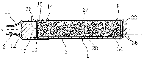
FIG. 6 shows a nicotine holder 1 according to a third
embodiment of the present invention, and this nicotine
holder contains a large number of liquid absorbent granules
34 in place of the liquid absorbent 4. The liquid
CA 02520759 2005-09-28
- 15 -
absorbent granules 34 are filled in a transparent outer
tube 3. The gaps between the liquid absorbent granules 34
and the gaps between the inner peripheral surface of the
outer tube 3 and the liquid absorbent granules 34 form
nicotine inhalation paths 27 and 28 inside the outer tube
3.
The outer tube 3 has end walls 22 at both ends, and a
plurality of openings 36 are formed in each end wall 22.
The openings 36 have a diameter significantly smaller than
that of the liquid absorbent granules 34, and accordingly,
the liquid absorbent granules 34 do not pass through the
openings 36 to the outside of the outer tube 3.
The liquid absorbent granules 34 are porous spherical
granules each having a large number of fine pores filled
with the nicotine solution. The diameter of the liquid
absorbent granules 34 is not particularly limited and may
preferably be 0.5 to 2 mm, for example. Also, the liquid
absorbent granules 34 may comprise either granules having
an identical diameter or a mixture of granules with
different diameters.
Specifically, the liquid absorbent granules 34 are
made of silica gel (e.g., CARiACT (registered trademark)
manufactured and sold by Fuji Silysia Chemical Ltd.),
activated carbon, zeolite, porous ceramic containing silica
gel as a main component, or a porous high polymer. In
order for the liquid absorbent granules 34 to have fine
pores of desired size, however, silica gel is preferably
used to form the liquid absorbent granules 34. In this
case, if the liquid absorbent granules 34 have fine pores
with an average diameter of 0.1 p,m or more, in other words,
if the total opening area of fine pores per 1 g of the
liquid absorbent granules 34 is approximately 30 m2 or
more, the liquid absorbent granules 34 can retain a
CA 02520759 2005-09-28
- 16 -
sufficient quantity of the nicotine solution. Moreover,
sufficient nicotine can be vaporized from the nicotine
solution (extract solution).
Further, the nicotine solution absorbed in the liquid
absorbent granules 34 is preferably colored using a
colorant. As the colorant, a food additive which is
vaporizable like nicotine is used.
The nicotine holder 1 shown in FIG. 6 also has the
seals 8 covering the openings 36 at both ends thereof. The
seals 8 are removed before the nicotine holder 1 is put to
use. The mouthpiece 2 is then attached to one end of the
nicotine holder 1, whereby the inhalation pipe is
assembled.
When air is inhaled through the inhalation pipe, a
negative pressure is created in the nicotine inhalation
paths 27 and 28 in the outer tube 3, promoting vaporization
of nicotine from the nicotine solution in the liquid
absorbent granules 34 into the nicotine inhalation paths 27
and 28. The vaporized nicotine flows through the nicotine
inhalation paths 27 and 28, together with the air
introduced from the openings 36 at the other end of the
outer tube 3, and is sucked into the consumer's mouth
through the filter 12 in the mouthpiece 2.
As the inhalation pipe is repeatedly puffed and thus
the nicotine in the nicotine solution is consumed, the
liquid absorbent granules 34 gradually become white. The
outer tube 3 is transparent or is semitransparently
colored; therefore, the consumer can visually check the
change in color of the liquid absorbent granules 34 through
the outer tube 3, permitting him/her to confirm with ease
the remaining amount of the nicotine in the nicotine
solution, that is, the consumption limit of the nicotine
holder 1.
CA 02520759 2005-09-28
- 17 -
Specifically, after the inhalation pipe is puffed 30
to 50 times, the liquid absorbent granules 34 in the outer
tube 3, that is, the colored granules of silica gel begin
to turn pale from those granules located at the other end
of the outer tube 3, that is, the air inlet side of the
nicotine holder, and the color of the granules finally
changes to white, which is the original color of silica
gel. Namely, those liquid absorbent granules 34 located at
the air inlet side are exposed to fresh air at all times,
and therefore, vaporization of nicotine from the nicotine
solution progresses faster at the air inlet side than at
the mouthpiece side of the inhalation pipe. Consequently,
the liquid absorbent granules 34, that is, the outer tube 3
whitens gradually from the air inlet side toward the
mouthpiece 2.
FIG. 7 shows a nicotine holder 1 according to a fourth
embodiment of the present invention, and this nicotine
holder is provided with a heating sheet 38. The heating
sheet 38 is wrapped around the outer peripheral surface of
the outer tube 3 except the end portion which is to be
inserted into the mouthpiece 2. The heating sheet 38
generates heat by the action of oxidation, for example, and
before the nicotine holder 1 is put to use, the outer
surface of the heating sheet 38 is covered with an outside
air shutoff film 40.
With this nicotine holder 1, as the air shutoff film
40 is peeled from the heating sheet 38, the heating sheet
38 generates heat and the generated heat promotes the
vaporization of nicotine inside the outer tube 3, making it
possible to increase the amount of nicotine taken in by the
consumer per unit time.
When the aforementioned nicotine holders 1 shown in
FIGS. 1 through 7 are put to use, the nicotine holder is
CA 02520759 2005-09-28
- 18 -
combined with the mouthpiece 2 to constitute the nicotine
inhalation pipe. The nicotine holder 1 and the mouthpiece
2 may, however, be combined together in advance as a one-
piece inhalation pipe. In this case, to prevent
vaporization of nicotine from the nicotine holder 1, the
tip opening of the mouthpiece 2 and the outer end of the
nicotine holder 1 are respectively covered with seals 8, as
indicated by the two-dot chain lines in FIG. 3.
The inhalation pipe or the nicotine holder may in its
entirety be wrapped in film, and in this case the seals 8
are unnecessary.