Language selection

Search

Patent 2520778 Summary

Third-party information liability

Some of the information on this Web page has been provided by external sources. The Government of Canada is not responsible for the accuracy, reliability or currency of the information supplied by external sources. Users wishing to rely upon this information should consult directly with the source of the information. Content provided by external sources is not subject to official languages, privacy and accessibility requirements.

Claims and Abstract availability

Any discrepancies in the text and image of the Claims and Abstract are due to differing posting times. Text of the Claims and Abstract are posted:

  • At the time the application is open to public inspection;
  • At the time of issue of the patent (grant).
(12) Patent: (11) CA 2520778
(54) English Title: HELICOPTER ROTOR
(54) French Title: ROTOR D'HELICOPTERE
Status: Deemed Expired
Bibliographic Data
(51) International Patent Classification (IPC):
  • B64C 27/51 (2006.01)
  • B64C 27/48 (2006.01)
(72) Inventors :
  • PANCOTTI, SANTINO (Italy)
(73) Owners :
  • LEONARDO S.P.A.
(71) Applicants :
  • LEONARDO S.P.A. (Italy)
(74) Agent: SMART & BIGGAR LP
(74) Associate agent:
(45) Issued: 2013-04-02
(22) Filed Date: 2005-09-23
(41) Open to Public Inspection: 2006-03-28
Examination requested: 2010-07-20
Availability of licence: N/A
Dedicated to the Public: N/A
(25) Language of filing: English

Patent Cooperation Treaty (PCT): No

(30) Application Priority Data:
Application No. Country/Territory Date
04425726.9 (European Patent Office (EPO)) 2004-09-28

Abstracts

English Abstract

There is described a rotor for a helicopter, having a hub rotating about a first axis; a number of blades projecting from the hub in respective longitudinal directions lying in a plane crosswise to the first axis, and each connected to the hub so as to be movable at least about a second axis crosswise to the first axis and to the relative longitudinal direction; and a number of damping devices for damping vibration of the helicopter, and each interposed between a respective blade, and the hub; each damping device has a plate member fixed, on one side, to the hub, connected, on the opposite side, to the relative blade by elastic means, and flexible, during movement of the blade, about a third axis coaxial with the second axis.


French Abstract

Un rotor d'hélicoptère est décrit ayant un moyeu en rotation par rapport à un premier axe, un nombre de pales se projetant du moyeu dans les directions longitudinales respectives reposant dans un plan perpendiculaire au premier axe et chacune étant reliée au moyeu de sorte à être mobile dans au moins un deuxième axe perpendiculaire au premier axe et à la direction longitudinale relative et un nombre de dispositifs d'atténuation pour atténuer la vibration de l'hélicoptère, et chacun étant interposé entre une pale respective et le moyeu; chaque dispositif d'atténuation a un élément de plaque fixé, sur un côté, au moyeu, relié, sur le côté opposé, à la pale relative par des moyens élastiques et souples, pendant le mouvement de la pale, autour d'un troisième axe coaxial par rapport au deuxième axe.

Claims

Note: Claims are shown in the official language in which they were submitted.

CLAIMS
1) A rotor for a helicopter, comprising:
a hub rotating about a first axis, and comprising a radially
inner cylindrical body and a radially outer tubular portion;
a plurality of blades projecting from said hub in respective
longitudinal directions lying in a plane crosswise to said first
axis, each blade being connected to said hub so as to be movable at
least about a second axis crosswise to said first axis and to the
relative longitudinal direction; and
a plurality of damping devices for damping vibration of said
helicopter, and each interposed between a respective one of said
blades and said tubular portion of said hub, each damping device
comprising a separate plate member fixed on one side to said hub, and
connected on an opposite side to its respective blade by elastic
means; said plate member, during movement of said blade, being
flexible about a third axis parallel to said second axis and located
close to the second axis;
each plate member being V-shaped and comprising:
a tip which is connected to the respective blade;
two diverging lateral branches which originate from said tip;
and
an end, opposite to said tip, which is defined by free ends of
said lateral branches and which is connected to said tubular portion
of said hub, said lateral branches of each said plate member being

11
spaced from each other and defining together with said tip a cavity
for receiving part of said tubular portion of said hub.
2) A rotor as claimed in Claim 1, wherein said third axis is
coaxial with said second axis.
3) A rotor as claimed in Claim 1 or 2, wherein said plate member
is connected to said elastic means by an articulated connection.
4) A rotor as claimed in any one of claims 1 to 3 wherein each
said blade comprises, close to said hub, a frame-like portion
defining a seat for housing a respective one of said damping devices.

Description

Note: Descriptions are shown in the official language in which they were submitted.


CA 02520778 2005-09-23
1
HELICOPTER ROTOR
The present invention relates to a helicopter rotor
of the type substantially comprising a hub connected to a
drive shaft to rotate the rotor; and a number of blades
fixed to and projecting radially from the hub.
More specifically, each blade extends lengthwise
substantially radially, is rotated, in use, by the hub in
a drive plane perpendicular to the axis of the drive
shaft, and is movable in all planes with respect to the
hub to manoeuvre the helicopter.
Established helicopter design criteria require that,
for each operating condition of the helicopter, the work
frequencies of the rotor and blades fall within a
different range from that of the natural frequencies of
the other component parts of the helicopter.
If such is not the case, the helicopter may be
subjected to particularly severe, even destructive,
vibration.
In helicopter design, appropriate setting of said
natural frequencies is therefore essential; for which
purpose, vibration damping devices are known to be

CA 02520778 2005-09-23
2
interposed between the hub and each blade, either inwards
or outwards of the blades.
Location of the damping device outwards of the
blades produces additional aerodynamic drag which impairs
performance and consumption of the helicopter.
To reduce such drag, the damping devices must be
made as small as possible. By so doing, however, the
loads acting on the rotor may induce severe stress on,
and even cause detachment of, the damping devices, thus
l0 resulting in malfunctioning of the rotor and possibly
additional stress on the helicopter, making it difficult
to manoeuvre.
Moreover, if detached, the damping device may hit
the helicopter rotor, with obvious consequences in terms
of safety.
Conversely, location of the damping device inwards
of the blade poses problems caused by the damping device
interacting with the portion of the blade connected to
the hub, and by sliding movements between the contacting
parts .
More specifically, such sliding movements may
produce wear and localized heating of the contacting
parts, thus reducing the working life of the parts and
dissipating energy at the expense of the efficiency of
the helicopter.
Location of the damping devices inwards of the
blades also poses size problems, making it necessary at
times to redesign the rotor hub.

CA 02520778 2005-09-23
3
It is an object of the present invention to provide
a helicopter rotor designed to eliminate at least some of
the aforementioned drawbacks in a straightforward, low-
cost manner.
According to the present invention, there is
provided a helicopter rotor as claimed in Claim 1.
A preferred, non-limiting embodiment of the present
invention will be described by way of example with
reference to the accompanying drawings, in which:
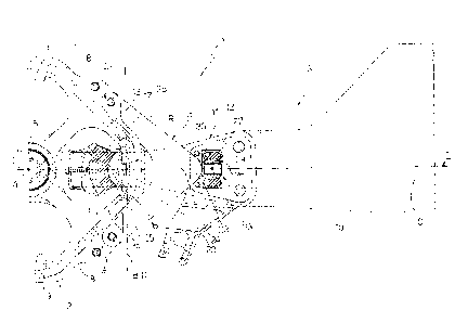
Figure 1 shows a partial longitudinal section of a
helicopter rotor in accordance with the present
invention;
Figures 2 and 3 show smaller-scale sections, along
line II-II in Figure 1, of the rotor in two different
operating conditions.
Number 1 in the accompanying drawings indicates as a
whole a rotor, for a helicopter (not shown),
substantially comprising a hub 2 of axis A; a number of
blades 3 (only one shown in detail) projecting
substantially radially from hub 2; and a number of
damping devices 4 (only one shown in detail), each
interposed between a respective blade 3 and hub 2 to
reduce the vibration induced on the helicopter by rotor
1.
More specifically, hub 2 comprises a radially inner
cylindrical body 5, of axis A, for housing a drive shaft
6 of rotor 1; and a radially outer tubular portion 7
having a curved polygonal profile and connected to

CA 02520778 2005-09-23
4
cylindrical body 5 by a number of angularly equally
spaced radial spokes 8.
In other words, hub 2 comprises a number of through
seats 9, of axis A, equally spaced about axis A and by
which to attach respective blades 3.
More specifically, each seat 9 is bounded
circumferentially by two adjacent spokes 8, and radially
by cylindrical body 5 and tubular portion 7.
As shown in the accompanying drawings, each blade 3
extends predominantly in a direction C substantially
radial with respect to axis A, and comprises a main body
10 (shown only partly in the accompanying drawings)
defining the helicopter lift/flight surfaces; and a
coupling member 11 bolted to a radially inner end of main
body 10 to connect blade 3 to hub 2.
More specifically, coupling member 11 of each blade
3 is substantially C-shaped, and comprises two parallel
arms 12, between which the radially inner end of main
body 10 of blade 3 is fixed; and a connecting portion 13
connecting arms 12 and which engages a respective seat 9
o f hub 2 .
More specifically, connecting portion 13 of coupling
member 11 of each blade 3 engages a respective seat 9 of
hub 2 with the interposition of a bearing 15 allowing
blade 3 to move in all possible planes in space about a
centre of rotation R.
More specifically, each bearing 15 is housed between
a convex circumferential projection 16 formed on tubular

CA 02520778 2005-09-23
portion 7 of hub 2 at relative seat 9, and a concave
recess 17 complementary in shape and formed on connecting
portion 13 of coupling member 11 of relative blade 3.
As shown clearly in the accompanying drawings, each
5 projection 16 on tubular portion 7 of hub 2 faces axis A,
while each recess 17 is formed on the side of connecting
portion 13 of relative blade 3 facing away from axis A.
Given the construction arrangement described above,
each blade 3 can be rotated integrally with hub 2 in a
plane perpendicular to axis A, and is movable with
respect to hub 2 about centre of rotation R.
More specifically, of all the possible movements of
each blade 3, the most significant, for a clear
understanding of the present invention, is that about an
axis B extending through centre of rotation R and
perpendicular to axis A and direction C. The other known
possible movements of blades 3 are not described for the
sake of simplicity.
As shown in Figures 2 and 3, each damping device 4
is housed between arms 12 of coupling member 11 of
relative blade 3, and is secured, on one side, to arms
12, and, on the opposite side, to tubular portion 7 of
hub 2.
More specifically, each damping device 4 is enclosed
between arms 12 in a direction parallel to axis A, and is
enclosed radially between tubular portion 7 of hub 2 and
the radially inner end of main body 10 of relative blade
3. In other words, each coupling member 11 defines a

CA 02520778 2005-09-23
6
frame-like portion, of relative blade 3, in turn defining
a seat 18 open in a direction parallel to axis B and for
housing a relative damping device 4.
Each damping device 4 advantageously comprises a
plate member 20, the radially inner end 21 of which, with
respect to axis A, is fixed to tubular portion 7 of hub
2, and the radially outer end 22 of which, with respect
to axis A, is secured to arms 12 of coupling member 11 of
relative blade 3 by means of a connecting member 23 made
partly of elastic material.
More specifically, plate member 20 is V-shaped, lies
in a plane parallel to arms 12 of coupling member 11 of
relative blade 3, and is symmetrical with respect to
direction C.
More specifically, plate member 20 comprises a tip
portion 24, from which originate two diverging lateral
branches 25.
Tip portion 24 defines end 22 of plate member 20,
while the free ends of lateral branches 25 together
define end 21 connecting plate member 20 to tubular
portion 7 of hub 2.
Tip portion 24 of plate member 20 has an end ball 26
connected to connecting member 23 to define an
articulated joint as explained in detail later on.
More specifically, connecting member 23 comprises a
parallelepiped-shaped supporting member 27 fixed between
the free ends of arms 12, with the interposition of
respective pads 28 of elastomeric material, and defining

CA 02520778 2005-09-23
7
a spherical seat 30 for housing ball 26 of plate member
20 with the interposition of a bearing 29 also made of
elastomeric material.
As shown particularly in Figure 1, lateral branches
25 are fixed peripherally to tubular portion 7 of hub 2,
and define, together with tip portion 24, a cavity for
receiving part of tubular portion 7; which construction
arrangement provides for limiting the overall size of
rotor 1 radially with respect to axis A.
An important characteristic of the present invention
is that, during movement of relative blade 3, plate
member 20 is flexible about an axis D coaxial with axis
B.
Axes D and B being coaxial, no sliding movements
occur, as each blade 3 rotates about axis B, between
relative plate member 20 and the parts connecting plate
member 20 to hub 2 and blade 3, thus drastically reducing
wear and localized heating.
In an alternative embodiment not shown, the same
results may also be achieved with axis D located close to
and parallel to axis B. More specifically, axis D may be
located at a distance from axis B equal to no more than
lOs, and preferably within 5s, of the total length of
plate member 20 in direction C.
Further advantages of rotor 1 as described and
illustrated herein are indicated below.
In particular, being V-shaped, each plate member 20
is far more resistant to bending moments operating in a

CA 02520778 2005-09-23
8
plane defined by axis A and relative direction C, and to
shear forces perpendicular to direction C.
In fact, each plate member 20 has a cross section,
crosswise to the plane of plate member 20, characterized
by decreasing in area and moment of inertia from axis A
towards relative connecting member 23.
The resistance of plate member 20 to said bending
moments is therefore optimized, by the sections close to
axis D, and therefore subjected to greater stress by the
l0 bending loads on blade 3, having a greater moment of
inertia.
Similarly, close to axis A, the resistance of plate
member 20 to shear stress is improved, by plate member 20
having larger-area sections close to axis A.
Each damping device 4 is therefore characterized by
being smaller in overall size radially with respect to
axis A, and by improved resistance to external stress as
compared with known solutions.
Moreover, if detached accidentally from rotor 1,
each damping device 4 remains inside relative seat 18,
and is prevented from escaping from relative blade 3 and
possibly colliding with rotor 1.
In other words, in the above conditions,
malfunctioning of rotor 1 and additional stress on the
helicopter are therefore reduced.
Finally, housing each damping device 4 inside a
closed seat 18 defined by relative blade 3 produces no
additional aerodynamic drag, thus improving performance

CA 02520778 2005-09-23
9
and consumption of the helicopter.
Clearly, changes may be made to rotor 1 as described
and illustrated herein without, however, departing from
the scope defined by the accompanying Claims.

Representative Drawing
A single figure which represents the drawing illustrating the invention.
Administrative Status

2024-08-01:As part of the Next Generation Patents (NGP) transition, the Canadian Patents Database (CPD) now contains a more detailed Event History, which replicates the Event Log of our new back-office solution.

Please note that "Inactive:" events refers to events no longer in use in our new back-office solution.

For a clearer understanding of the status of the application/patent presented on this page, the site Disclaimer , as well as the definitions for Patent , Event History , Maintenance Fee  and Payment History  should be consulted.

Event History

Description Date
Letter Sent 2024-03-25
Letter Sent 2023-09-25
Inactive: Correspondence - Transfer 2020-08-21
Common Representative Appointed 2019-10-30
Letter Sent 2019-10-23
Inactive: Multiple transfers 2019-10-09
Change of Address or Method of Correspondence Request Received 2018-01-12
Inactive: Office letter 2016-03-03
Inactive: Correspondence - MF 2016-01-11
Grant by Issuance 2013-04-02
Inactive: Cover page published 2013-04-01
Pre-grant 2013-01-17
Inactive: Final fee received 2013-01-17
Notice of Allowance is Issued 2012-10-15
Letter Sent 2012-10-15
Notice of Allowance is Issued 2012-10-15
Inactive: Approved for allowance (AFA) 2012-09-28
Amendment Received - Voluntary Amendment 2012-03-28
Inactive: S.30(2) Rules - Examiner requisition 2011-12-02
Letter Sent 2010-08-04
Request for Examination Requirements Determined Compliant 2010-07-20
All Requirements for Examination Determined Compliant 2010-07-20
Request for Examination Received 2010-07-20
Letter Sent 2006-11-08
Inactive: Single transfer 2006-09-20
Inactive: Cover page published 2006-03-30
Inactive: IPC assigned 2006-03-29
Inactive: First IPC assigned 2006-03-29
Inactive: IPC assigned 2006-03-29
Application Published (Open to Public Inspection) 2006-03-28
Inactive: Courtesy letter - Evidence 2005-11-08
Inactive: Filing certificate - No RFE (English) 2005-11-04
Filing Requirements Determined Compliant 2005-11-04
Application Received - Regular National 2005-11-04

Abandonment History

There is no abandonment history.

Maintenance Fee

The last payment was received on 2012-09-07

Note : If the full payment has not been received on or before the date indicated, a further fee may be required which may be one of the following

  • the reinstatement fee;
  • the late payment fee; or
  • additional fee to reverse deemed expiry.

Please refer to the CIPO Patent Fees web page to see all current fee amounts.

Owners on Record

Note: Records showing the ownership history in alphabetical order.

Current Owners on Record
LEONARDO S.P.A.
Past Owners on Record
SANTINO PANCOTTI
Past Owners that do not appear in the "Owners on Record" listing will appear in other documentation within the application.
Documents

To view selected files, please enter reCAPTCHA code :


To view images, click a link in the Document Description column. To download the documents, select one or more checkboxes in the first column and then click the "Download Selected in PDF format (Zip Archive)" or the "Download Selected as Single PDF" button.

List of published and non-published patent-specific documents on the CPD .

If you have any difficulty accessing content, you can call the Client Service Centre at 1-866-997-1936 or send them an e-mail at CIPO Client Service Centre.


Document
Description 
Date
(yyyy-mm-dd) 
Number of pages   Size of Image (KB) 
Cover Page 2013-03-05 2 53
Description 2005-09-23 9 252
Abstract 2005-09-23 1 19
Claims 2005-09-23 2 42
Drawings 2005-09-23 3 96
Representative drawing 2006-03-02 1 19
Cover Page 2006-03-30 1 47
Claims 2012-03-28 2 48
Representative drawing 2013-03-05 1 19
Filing Certificate (English) 2005-11-04 1 158
Request for evidence or missing transfer 2006-09-26 1 101
Courtesy - Certificate of registration (related document(s)) 2006-11-08 1 105
Reminder of maintenance fee due 2007-05-24 1 112
Reminder - Request for Examination 2010-05-26 1 129
Acknowledgement of Request for Examination 2010-08-04 1 178
Courtesy - Patent Term Deemed Expired 2024-05-06 1 554
Commissioner's Notice - Application Found Allowable 2012-10-15 1 162
Commissioner's Notice - Maintenance Fee for a Patent Not Paid 2023-11-06 1 550
Correspondence 2005-11-04 1 25
Fees 2007-07-31 1 28
Fees 2008-07-30 1 34
Fees 2009-09-03 1 34
Fees 2010-07-19 1 35
Correspondence 2013-01-17 1 52
Correspondence 2016-01-11 7 318
Courtesy - Office Letter 2016-03-03 1 23