Language selection

Search

Patent 2520838 Summary

Third-party information liability

Some of the information on this Web page has been provided by external sources. The Government of Canada is not responsible for the accuracy, reliability or currency of the information supplied by external sources. Users wishing to rely upon this information should consult directly with the source of the information. Content provided by external sources is not subject to official languages, privacy and accessibility requirements.

Claims and Abstract availability

Any discrepancies in the text and image of the Claims and Abstract are due to differing posting times. Text of the Claims and Abstract are posted:

  • At the time the application is open to public inspection;
  • At the time of issue of the patent (grant).
(12) Patent Application: (11) CA 2520838
(54) English Title: CALIBRATION DEVICE
(54) French Title: DISPOSITIF DE CALIBRAGE
Status: Deemed Abandoned and Beyond the Period of Reinstatement - Pending Response to Notice of Disregarded Communication
Bibliographic Data
(51) International Patent Classification (IPC):
  • B29C 48/90 (2019.01)
(72) Inventors :
  • STIEGLITZ, HENNING (Germany)
(73) Owners :
  • KRAUSSMAFFEI TECHNOLOGIES GMBH
(71) Applicants :
  • KRAUSSMAFFEI TECHNOLOGIES GMBH (Germany)
(74) Agent: SMART & BIGGAR LP
(74) Associate agent:
(45) Issued:
(86) PCT Filing Date: 2004-03-30
(87) Open to Public Inspection: 2004-10-14
Availability of licence: N/A
Dedicated to the Public: N/A
(25) Language of filing: English

Patent Cooperation Treaty (PCT): Yes
(86) PCT Filing Number: PCT/EP2004/003333
(87) International Publication Number: EP2004003333
(85) National Entry: 2005-09-29

(30) Application Priority Data:
Application No. Country/Territory Date
103 15 125.7 (Germany) 2003-04-03

Abstracts

English Abstract


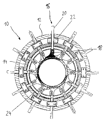
The invention relates to a calibration device for calibrating extruded
continuous profile, in particular tubes. The inventive device comprises a
plurality of successively arranged segmented crowns consisting of individual
segments (18, 18', 18'') whose internal surfaces jointly form a calibration
opening. Said successively axially arranged segments (18, 18', 18'') are
assembled in the form of a segmented block (16). The individual segments (18,
18', 18'') of each segmented block (16) are arranged on a support structure
(30, 30'), and the segmented blocks (16) are arranged, in an essentially
circular form, in a body (12, 14) in such a way that the axially adjacent
segments (18, 18', 18'') are partially superposed upon each other at each
position thereof in a circumferential direction. Each support structure (30,
30') is connected to at least one fixing and actuating (20,20') device. The
individual segmented blocks (16) which are associated to the support
structures (30, 30') thereof are fixed to the body (12, 14) with the aid of
said fixing and actuating (20, 20') device, the adjustment of each segmented
block (16) being carried out in an axial direction. In order to facilitate the
integration and assembly, each fixing and actuating device (20, 20') is
divided into two parts, i.e. the first part (42, 60) connected to the support
structure (30, 30') and the second part (40, 62) arranged in the body (12,
14), said two parts are mutually assembled in a separable manner.


French Abstract

L'invention concerne un dispositif de calibrage utilisé pour le calibrage de profilés continus extrudés, en particulier de tubes. Ce dispositif comprend une pluralité de couronnes segmentées placées l'une derrière l'autre, constituées de segments (18, 18', 18") individuels, dont les surfaces intérieures forment ensemble une ouverture de calibrage. Des segments (18, 18', 18") placés l'un derrière l'autre dans le sens axial sont assemblés en un bloc segmenté (16). Les segments (18, 18', 18") individuels de chaque bloc segmenté (16) sont disposés sur une structure de support (30, 30'), et les blocs segmentés (16) sont, selon une forme sensiblement circulaire, logés dans un corps (12, 14) de telle sorte que des segments (18, 18', 18") axialement voisins se chevauchent partiellement dans chaque position, dans le sens circonférentiel. Chaque structure de support (30, 30') est reliée à au moins un dispositif de fixation et d'actionnement (20, 20'), avec lequel les blocs segmentés (6) individuels associés à leur structure de support (30, 30') propre sont fixés dans le corps (12, 14), un réglage de chacun de ces blocs segmentés (16) individuels pouvant être effectué dans le sens axial. Pour une intégration et un montage plus faciles, il est proposé que chaque dispositif de fixation et d'actionnement (20, 20') soit divisé en deux, à savoir en une première partie (42, 60), qui est reliée à la structure de support (30, 30'), et en une seconde partie (40, 62), qui est logée dans le corps (12, 14), ces deux parties étant elles-mêmes assemblées mutuellement de façon séparable.

Claims

Note: Claims are shown in the official language in which they were submitted.


10
CLAIMS
1. Calibration device for calibrating extruded continuous profiles, in
particular
tubes, comprising a plurality of segment rings which are disposed behind
one another and include individual segments (18, 18', 18") and whose inner
surface jointly define a calibrating opening, wherein
- segments (18, 18', 18") disposed behind one another in axial direction
are combined to a segment block (16),
- the individual segments (18, 18', 18") of each segment block (16) are
arranged on a support structure (30, 30'),
- the segment blocks (16) are received in substantial circular manner in
a housing (12, 14) such that axially adjacent segments (18, 18', 18")
partially overlap in each position in circumferential direction, and
- each support structure (30, 30') is connected with at least one
mounting and operating device (20, 20') which restrains the individual
segment blocks (16), associated to a respective support structure (30,
30'), in the housing (12, 14), and enables an adjustment of each
individual segment block (16) in radial direction,
characterized in that
each mounting and operating device (20, 20') is made of two parts, wherein
a first part (42, 60) is connected with the support structure (30, 30'), and a
second part (40, 62) is received in the housing (12, 14), and both parts are
connected with one another in a detachable manner.
2. Calibration device according to claim 1,
characterized in
that the mounting and operating device (20, 20') is constructed as spindle
drive, wherein a spindle (20, 20') with an outer thread portion being
arranged on the support structure (30, 30'), and the outer thread portion
interacts with a gear nut (22) which is rotatably driven via a further drive

11
element, and wherein the spindle (20, 20') is made of two parts, with a first
part (42, 60) which is connected to the support structure (30, 30'), and a
second part (40, 62) which includes the outer thread portion.
3. Calibration device according to claim 2,
characterized in
that the second part (40) of the spindle, received in the housing (12, 14), is
configured in the form of a rod with an outer thread.
4. Calibration device according to claim 2 or 3,
characterized in
that the support structure (30, 30') for the individual segments (18, 18',
18")
of a segment block (16) includes at least one rod (52, 54) on which the
individual segments (18, 18', 18") are lined up, and the rod: (52, 54) is
received in a bore (46) of the first part of the spindle (42, 60).
5. Calibration device according to one of the claims 2 to 4,
characterized in
that two spindles (20, 20') are provided which are disposed on the support
structure (16) in axially offset relationship.
6. Calibration device according to claim 2,
characterized in
that the spindle (20') includes a first spindle mounting (60) which is
connected to the support structure and includes a spindle rod, and that the
spindle rod is received at substantial precision fit in a spindle sleeve (62)
with an outer thread, wherein the spindle mounting (60) and the spindle
sleeve (62) are securable relative to one another.

12
7. Calibration device according to claim 6,
characterized in
that a thread is provided on the end of the spindle rod in opposition to the
support structure (30, 30'), and the spindle sleeve (62) is securable in
relation to the spindle rod by threadably engaging a nut (64) upon the
thread.

Description

Note: Descriptions are shown in the official language in which they were submitted.


CA 02520838 2005-09-29
WO 2004/087400 PCT/EP20041003333
1
CALIBRATION DEVICE
The invention relates to a calibration device according to the preamble of
claim 1.
Calibration devices are used, for example, for calibrating extruded continuous
profiles, in particular tubes. Plastic melt is hereby initially prepared in an
extruder
and shaped by an exit nozzle. To assure the desired dimensioning of the
continuous profile, the latter travels through the calibration device after
the
shaping operation for providing precise size thereof.
Up to some time ago, the production of plastic tubes required the availability
of
various calibration devices for different wall thicknesses or outer diameters.
Hereby, the tools needed to be replaced, requiring a shutdown of the machine
which leads to downtimes.
DE 198 43 340 C2 thus proposed to use an adjustable calibration device for
different tube dimensions. This calibration device includes a plurality of
lamellae
which are distributed in spaced-apart relationship about the circumference on
the
outer sides of the tube to be sized. Viewed in production direction of the
tube, a
plurality of such lamellae rings is disposed within a calibration station,
with the
individual lamellae of the individual lamellae rings positioned with clearance
to
thereby permit easy adjustment of the lamellae of the individual rings in
relation
to the lamellae of the subsequent ring or the preceding ring. The lamellae are
united in segments to form a lamellae block and supported by a holding
structure. The holding structure in tum is connected to the housing for radial
adjustment.
A problem of this construction of the calibration device is however the single-
piece configuration of the holding structure. It has been shown during
production
of the calibration device that part of the holding structure, namely the
adjustable

CA 02520838 2005-09-29
WO 20041087400 PCTIEP2004/003333
2
part, must be first inserted in the housing. Then, the individual lamellae are
secured to the support and holding structure in a manner that is difficult to
implement.
It is an object of the present invention, to provide a calibration device
which can
be made and assembled in a simple manner.
This object is attained by the features set forth in claim 1.
The basic idea of the present invention is the construction of the mounting
and
operating device itself in two parts, whereby a first part of the mounting and
operating device may be received in the housing independently from a second
part. The second part of the mounting and operating device may serve as part
of
the support structure or may be connected therewith. This enables the
arrangement of the individual lamellae on the support structure outside the
housing so that the support structure can then - while the segment blocks are
completed as such - be installed in the housing. Both parts of the mounting
and
operating device are hereby connected to one another.
This construction has proven advantageous especially in those circumstances
when the second part of the mounting and operating device, received in the
housing, is configured for radial adjustment of the respective segment blocks
and
oftentimes is thus incorporated in the housing in a structurally complex
manner.
According to a preferred embodiment, the mounting and operating device is
constructed in the form of a spindle drive, wherein - according to an
embodiment - a spindle is arranged upon the support structure with an outer
thread portion. The outer thread portion interacts with a spindle nut which is
rotatably driven via a further drive element. The spindle is hereby
constructed in

CA 02520838 2005-09-29
WO 20041087400 PCTIEP20041003333
3
two parts, with a first part connected to the support structure, and with a
second
part which includes the outer thread portion.
The connection of both parts of the mounting and operating device may involve
a
latch, a screw connection or similar conventional connection mechanisms.
A particularly simple embodiment is characterized by the construction of the
second part of the spindle, received in the housing, substantially in the form
of a
threaded rod with an outer thread.
The support structure may include a rod or a bar for successive stringing of
individual segments of a segment block. The segments are spaced from one
another at predefined distances by spacer sleeves. The first part of the
spindle
would then be connected with such a rod or bar of the support structure.
Preferably, this part may hereby be provided with a bore for passage of the
rod
or bar. Of course, it is also possible to stabilize the entire device by
providing two
or more rods or bars for the support structure. As an alternative, the support
structure may also be constructed differently.
A further preferred embodiment of the invention is characterized in that the
spindles are each comprised of a spindle mounting and a spindle sleeve. The
spindle mounting includes a spindle rod and an adjacent part which is
connected
to the support structure. The spindle rod is received with precision fit and
fixedly
securable in the spindle sleeve. In this embodiment, the spindle sleeve having
an
outer thread could be inserted into the housing without the spindle rod. The
individual segment blocks could then be placed in a pertaining spindle sleeve
into
the housing by inserting the respective spindle rod. Once placed, the
respective
spindle rods and spindle sleeves are braced with one another, by a screwed
connection for example, so as to realize a securement of spindle mounting and
spindle sleeve.

CA 02520838 2005-09-29
WO 20041087400 PCTIEP2004/003333
4
Securement may be realized for example by providing a thread at the end of the
spindle rod in opposition to the support structure, and by threadably engaging
a
nut on the spindle to secure or clamp the spindle sleeve in relation to the
spindle
rod.
Two preferred embodiments of the invention will now be described in greater
detail with reference to the attached drawings in which:
Fig. 1 shows a schematic sectional illustration of an embodiment of a
calibration device according to the invention in perpendicular relationship to
the
production direction of a tube,
Fig. 2 shows a schematic sectional illustration of a calibration device like
in Fig. 1 in parallel relationship to the production direction,
Fig. 3 shows a schematic simplified illustration of an individual segment
block from the calibration device of Figs. 1 and 2,
Fig. 4 shows two views of a first embodiment of a spindle support for
retaining a segment block,
Fig. 5 shows a further segment block with a further embodiment of a
spindle support, and
Fig. 6 shows a partial frontal view of a segment block.
A complete arrangement of an apparatus for making a plastic tube can be
gathered from DE 198 43 340 C2 which already illustrates an adjustable
calibration device. The adjustable calibration device is hereby a core
component
of a tube extrusion plant with option to change dimensions. It assumes the

CA 02520838 2005-09-29
WO 20041087400 PCTIEP20041003333
shaping task of a standard calibration, but may be infinitely adjustable
across a
diameter range which is predefined based on the construction.
This adjustment is rendered possible by forming the surface, which bears upon
the tube, with a great number of individual segments. The segments 18
illustrated in Fig. 1 are rounded along their circumferential direction of the
tube in
correspondence with the greatest possible outer tube diameter and are united
to
single segment rings. These segment rings are arranged in production direction
in spaced-apart relationship, positioned however snugly fitted behind one
another. Two successive segment rings are combined to a dimension ring and
arranged in offset relationship with clearance. This ensures the absence of
any
edges during passage of the tube through the calibration device. The
individual
segment surfaces form jointly a substantially smooth inner tube surface with
substantially circular geometry.
The segments 18 positioned axially behind one another in production direction
of
the tube are united to form a segment block. Used hereby is a support
structure 30 as will be described hereinafter in greater detail with reference
to
Fig. 5. The support structure 30 is connected with a mounting and operating
device 20 which connects the respective segment blocks with the housing of the
calibration device for radial adjustment. The housing of the calibration
device
includes according to the exemplary embodiment of Fig. 1 two cylinder
portions 12 and 14 arranged coaxially within one another. Received in these
cylinder portions in the form of a circle are the individual segment blocks
16. A
single segment block 16 of the first embodiment is depicted schematically in
Fig. 3.
It includes lamellae 18 arranged behind one another and secured to two support
rods. The support rods form the support structure 30. Disposed on the support
rods in turn are two spindle carriers 20 spaced in axial direction from one

CA 02520838 2005-09-29
WO 20041087400 PCT/EP20041003333
6
another. The spindle carriers 20 are shown in two views in Fig. 4 and include
an
attachment portion 42 which is connected or connectable to the support
structure 30, and a threaded rod 40. The threaded rod 40 and the attachment
portion 42 are detachably connectable with one another at the connection
position, for example by an unillustrated screw connection, clamp connection,
latch connection or other connection.
When the calibration device is completely assembled, the externally threaded
rods 40 are received in associated bores of the housing cylinders 12 and 14.
Provided for each externally threaded rod is a gear nut 22 between both
housing
cylinders 12 and 14 for interaction with the outer thread of the externally
threaded
rod 40 in an adjustable manner.
Disposed in form of a circle in perpendicular relationship to the production
direction of the tube 24 (compare Fig. 1 ) are 12 segment blocks. Each segment
block includes two spindle carriers 20 disposed in axially spaced-apart
relationship (Fig. 2) and respectively interacting with a pertaining gear nut
22.
The gear nuts 22 in tum are adjusted in unison by a gear ring 26 which extends
on the circumference between the axially spaced gear nuts 22. The gear ring 26
includes hereby on both its edges teeth which mesh with the gear nuts 22.
Actuation of the gear ring 26 enables radially outward or inward adjustment of
all
segment blocks simultaneously and in a same manner. Radial adjustment of all
segment blocks in like manner establishes a variable calibration diameter.
Thus,
the outer diameter of the tube 24 to be calibrated can be defined within the
adjustment range.
An advantage of the present embodiment is the two-part construction of the
mounting and operating device configured in the form of spindle carriers 20.
This
enables the insertion of the externally threaded rods 40 into the housing 12,
14

CA 02520838 2005-09-29
WO 20041087400 PCTIEP2004/003333
7
and their respective alignment. Parallel thereto, the segment blocks 16 can be
established by lining up the individual segments 18 on the support structure
30.
The support structure 30 is hereby firmly connected also with the attachment
portion 42.
As a consequence of the connection option between the attachment portion 42,
on one hand, and outer thread portion 40, on the other hand, the individual
segment blocks 16 can easily be placed into the housing 12, 14 without any
problem. In this way, the calibration device can be manufactured in a simple
and
cost-efficient manner.
A further embodiment of the invention is illustrated in Figs. 5 and 6 which
depict
in more detail a segment block 16'. This segment block 16' includes two
different
lamellae configurations 18' and 18" disposed in alternating relationship. Each
lamellae includes two bores and is thus strung on retention rods 52 and 54.
The
individual lamellae 18' and 18" are hereby separated from one another by
spacers. Disposed on the ends of the retention rods 52 and 54 are internal
threads so that insertion of a screw enables a bracing of all segments 18' and
18" with one another.
Received at two axial positions are a lower part of a spindle rod 60 instead
of the
spacer sleeves. The spindle rod 60 includes two bores through which the
retention rods 52 and 54 extend. The spindle rod 40 has the shape of a pin
above the attachment portion and terminates at its upper end with an outer
thread. Pushed over the spindle rod 60 is a spindle sleeve 62 which has an
outer
thread at its outer circumference. The spindle sleeve 62 bears with its lower
end
upon a seat of the spindle rod 60. At the upper end, the spindle sleeve is
secured
to the spindle rod 60 through screwed connection of the screw 64 to the outer
thread of the spindle rod.

CA 02520838 2005-09-29
WO 20041087400 PCT/EP2004I003333
8
When a calibration device is assembled in accordance with the second
embodiment, the lower part of the segment block 16' can be made while the
spindle rod 60 and spindle sleeve 62 are still separate, by pushing the
individual
lamellae 18' and 18" onto the respective support rods 52 and 54 using the
spacer sleeves, and subsequent threaded engagement to the ends of the
retention rods 52 and 54. The two spindle rods 60 are hereby integrated in the
support structure 30' in axially-spaced-apart relationship.
Parallel thereto, the spindle sleeves 62 are inserted in the calibration
housing,
not shown in greater detail here, and respectively adjusted. Then; the lower
parts
of the segment blocks 16' are inserted into the respective spindle sleeve 62
through insertion of the spindle rods 60: The segment blocks 16' are then
firmly
mounted in the housing by tightening the screw 64 and accompanying fixation of
the spindle rods and spindle sleeves 62.
In summary, the present invention ensures a simple and thus cost-efficient
assembly of the calibration device.

WO 20041087400 CA 02520838 2005-09-29 pCTIEP2004/003333
9
List of Reference characters
calibration basket
12 outer housing cylinder
14 inner housing cylinder
16 lamellae segment
block
18, 18', lamellae
18"
20, 20' spindle carrier
22 gear nut
24 tube
26 gear ring
30, 30' lamellae support
40 externally threaded
rod
42 attachment part
44 connection position
46 bores
52 lower support rod
54 upper support rod
60 inner spindle rod
62 spindle sleeve
64 bracing screw
66 screws

Representative Drawing
A single figure which represents the drawing illustrating the invention.
Administrative Status

2024-08-01:As part of the Next Generation Patents (NGP) transition, the Canadian Patents Database (CPD) now contains a more detailed Event History, which replicates the Event Log of our new back-office solution.

Please note that "Inactive:" events refers to events no longer in use in our new back-office solution.

For a clearer understanding of the status of the application/patent presented on this page, the site Disclaimer , as well as the definitions for Patent , Event History , Maintenance Fee  and Payment History  should be consulted.

Event History

Description Date
Inactive: IPC deactivated 2021-10-09
Inactive: First IPC from PCS 2019-01-12
Inactive: IPC from PCS 2019-01-12
Inactive: IPC expired 2019-01-01
Time Limit for Reversal Expired 2010-03-30
Application Not Reinstated by Deadline 2010-03-30
Deemed Abandoned - Failure to Respond to Maintenance Fee Notice 2009-03-30
Inactive: Abandon-RFE+Late fee unpaid-Correspondence sent 2009-03-30
Letter Sent 2008-08-07
Revocation of Agent Requirements Determined Compliant 2008-01-14
Inactive: Office letter 2008-01-14
Appointment of Agent Requirements Determined Compliant 2008-01-14
Appointment of Agent Request 2007-12-18
Revocation of Agent Request 2007-12-18
Revocation of Agent Requirements Determined Compliant 2007-11-02
Inactive: Office letter 2007-11-02
Appointment of Agent Requirements Determined Compliant 2007-11-02
Appointment of Agent Request 2007-10-10
Revocation of Agent Request 2007-10-10
Inactive: Cover page published 2006-01-16
Letter Sent 2006-01-12
Inactive: Notice - National entry - No RFE 2006-01-11
Application Received - PCT 2005-11-04
Inactive: Single transfer 2005-10-26
National Entry Requirements Determined Compliant 2005-09-29
Application Published (Open to Public Inspection) 2004-10-14

Abandonment History

Abandonment Date Reason Reinstatement Date
2009-03-30

Maintenance Fee

The last payment was received on 2008-02-21

Note : If the full payment has not been received on or before the date indicated, a further fee may be required which may be one of the following

  • the reinstatement fee;
  • the late payment fee; or
  • additional fee to reverse deemed expiry.

Patent fees are adjusted on the 1st of January every year. The amounts above are the current amounts if received by December 31 of the current year.
Please refer to the CIPO Patent Fees web page to see all current fee amounts.

Fee History

Fee Type Anniversary Year Due Date Paid Date
Basic national fee - standard 2005-09-29
Registration of a document 2005-10-26
MF (application, 2nd anniv.) - standard 02 2006-03-30 2006-02-23
MF (application, 3rd anniv.) - standard 03 2007-03-30 2007-02-22
MF (application, 4th anniv.) - standard 04 2008-03-31 2008-02-21
Registration of a document 2008-04-10
Owners on Record

Note: Records showing the ownership history in alphabetical order.

Current Owners on Record
KRAUSSMAFFEI TECHNOLOGIES GMBH
Past Owners on Record
HENNING STIEGLITZ
Past Owners that do not appear in the "Owners on Record" listing will appear in other documentation within the application.
Documents

To view selected files, please enter reCAPTCHA code :


To view images, click a link in the Document Description column. To download the documents, select one or more checkboxes in the first column and then click the "Download Selected in PDF format (Zip Archive)" or the "Download Selected as Single PDF" button.

List of published and non-published patent-specific documents on the CPD .

If you have any difficulty accessing content, you can call the Client Service Centre at 1-866-997-1936 or send them an e-mail at CIPO Client Service Centre.


Document
Description 
Date
(yyyy-mm-dd) 
Number of pages   Size of Image (KB) 
Description 2005-09-28 9 350
Representative drawing 2005-09-28 1 40
Drawings 2005-09-28 3 127
Claims 2005-09-28 3 86
Abstract 2005-09-28 1 38
Reminder of maintenance fee due 2006-01-10 1 110
Notice of National Entry 2006-01-10 1 192
Courtesy - Certificate of registration (related document(s)) 2006-01-11 1 104
Reminder - Request for Examination 2008-12-01 1 117
Courtesy - Abandonment Letter (Maintenance Fee) 2009-05-24 1 172
Courtesy - Abandonment Letter (Request for Examination) 2009-07-05 1 165
PCT 2005-09-28 5 241
Fees 2006-02-22 1 32
Fees 2007-02-21 1 34
Correspondence 2007-10-09 1 45
Correspondence 2007-11-01 1 20
Correspondence 2007-11-01 1 16
Correspondence 2007-12-17 4 112
Correspondence 2008-01-13 1 14
Correspondence 2008-01-13 1 19