Note: Descriptions are shown in the official language in which they were submitted.
CA 02521139 1998-09-02
METHODS OF COMPLETING AND PRODUCING A SUBTERRANEAN WELL
AND ASSOCIATED APPARATUS
BACKGROUND OF THE INVENTION
The present invention relates generally to operations performed in
subterranean wells and, in an embodiment described herein, more particularly
provides apparatus and methods for completing and producing a subterranean
well having multiple wellbores.
It is well known in the art of drilling subterranean wells to form a parent
bore into the earth and then to form one or more bores extending laterally
therefrom. Generally, the parent bore is first cased and cemented, and then a
tool known as a whipstock is positioned in the parent bore casing. The
whipstock is specially configured to deflect milling bits, drill bits, and/or
other
cutting tools in a desired direction for forming a lateral bore. A mill is
typically
lowered into the parent bore suspended from drill pipe and is radially
outwardly
deflected by the whipstock to mill a window in the parent bore casing and
cement. Directional drilling techniques may then be employed to direct further
drilling of the lateral bore outwardly from the window as desired.
The lateral bore may then be cased by inserting a tubular liner from the
parent bore, through the window previously cut in the parent bore casing and
cement, and into the lateral bore. In a typical lateral bore casing operation,
the
liner extends somewhat upwardly into the parent bore casing and through the
window when the casing operation is finished. In this way, an overlap is
achieved wherein the lateral bore liner is received in the parent bore casing
CA 02521139 1998-09-02
2
above the window. In another type of lateral bore casing operation, the liner
is
completely received within the lateral bore and does not extend into the
parent
bore when the casing operation is finished.
The lateral bore liner is then cemented in place by forcing cement
between the liner and the lateral bore. Where the liner extends into the
parent
bore, the cement is typically also forced between the liner and the window,
and
between the liner and the parent bore casing where they overlap. In this case,
the cement provides a seal between the liner, the parent bore casing, the
window, and the lateral bore. Where the liner does not extend into the parent
bore, the cement provides a seal between the liner and the lateral bore.
Further operations may then be performed in completing and/or
producing the well. For example, one or more tubing strings may be installed
in the well to conduct fluids from formations intersected by the parent and
lateral bores to the earth's surface, or to inject fluid into one or more of
the
formations. Unfortunately, these completion and/or production operations do
not provide means whereby fluid flow through the tubing strings may be
regulated in relatively close proximity to the formations and controlled from
the
earth's surface, in order to regulate rates of fluid flow from or into each of
the
formations, regulate the commingled proportions of fluids produced or injected
into each of the formations, control rates of production or injection to
comply
with regulations affecting such matters, etc.
CA 02521139 1998-09-02
3
For example, a flow choke, inline orifice or other flow regulating device
installed at the earth's surface is capable of influencing the rate of fluid
flow
through a single tubing string. However, when that tubing string conducts
fluid
produced from multiple formations or multiple intervals, the flow choke or
inline
orifice is not capable of regulating the proportional rate of fluid flow from
each
formation or interval. Of course, a separate flow choke or inline orifice may
be
provided for each formation or interval, but that would require a separate
tubing
string extending to the earth's surface for each formation or interval, which
would be expensive and often impossible to achieve. Additionally, it is well
known that wellbore storage effects make it much more desirable to regulate
fluid flows in close proximity to the formations or intervals, rather than at
the
earth's surface.
As another example, flow regulating devices may be installed in the well,
but past methods of accomplishing this have proved to be unsatisfactory. Most
such flow regulating devices require intervention into the well to vary the
rate of
fluid flow therethrough, such as by shifting a sleeve using a shifting tool
conveyed by wireline, slickline, tubing, etc. Others of such flow regulating
devices obstruct the inner diameter of the tubing string in which they are
installed.
From the foregoing, it can be seen that it would be quite desirable to
provide a method of completing and/or producing a well which does not rely on
flow regulating devices installed at the earth's surface, and which does not
CA 02521139 1998-09-02
4
require intervention into the well to vary rates of fluid flow into or out of
various
formations or intervals, but which permits accurate and convenient regulation
of fluid flow into or out of formations or intervals intersected by the well.
It is
accordingly an object of the present invention to provide such a method and
associated apparatus.
SUMMARY OF THE INVENTION
In carrying out the principles of the present invention, in accordance with
an embodiment thereof, a method is provided which permits a rate of fluid flow
into or out of each formation intersected by a well to be regulated from the
earth's surface. Furthermore, apparatus for facilitating performance of the
method is also provided.
In broad terms, a method provided by the present invention results in a
flow regulating device being installed within the well in relatively close
proximity
to each formation or interval intersected by the well for which it is desired
to
regulate the flow of fluids. The regulating devices may be remotely
controllable
from the earth's surface and may not require intervention into the well to
vary
rates of fluid flow therethrough.
In an embodiment of the invention described below, multiple tubing
strings are installed in the well, with one of the tubing strings extending
into a
lower parent wellbore, and another of the tubing strings extending into a
lateral
wellbore. A flow regulating device is interconnected in the tubing string
extending into the lateral wellbore, and another flow regulating device is
CA 02521139 1998-09-02
interconnected in yet another tubing string extending to the earth's surface.
Fluid flow through the tubing string extending into the lower parent wellbore
is
directed to an annulus disposed radially between the upper parent wellbore
casing and the tubing string extending to the earth's surface and axially
between two sealing devices. The flow regulating devices may be remotely
controllable.
In another embodiment of the present invention described below, each
tubing string extending into a wellbore intersecting a formation or interval
into,
or from which, fluid flow is to be regulated is provided with a flow
regulating
device interconnected therein. In this way, the rate of flow of fluid into or
from
each formation or interval may be independently controlled. The fluid flows
may or may not be directed through separate tubing strings extending to the
earth's surface, or commingled in one or more such tubing strings. Each flow
regulating device may be remotely controllable from the earth's surface.
In one aspect of the present invention, a releasable deflection device is
provided which enables a tubing string to be deflected off of a deflection
surface positioned at an intersection of a parent and a lateral wellbore, to
thereby direct the tubing string into the lateral wellbore. In one embodiment
described herein, the deflection device engages a tubular structure within the
lateral wellbore and releases a relatively large diameter outer housing for
displacement relative to the remainder of the tubing string.
CA 02521139 1998-09-02
6
These and other features, advantages, benefits and objects of the
present invention will become apparent to one of ordinary skill in the art
upon
careful consideration of the detailed description of representative
embodiments
of the invention hereinbelow and the accompanying drawings.
BRIEF DESCRIPTION OF THE DRAWINGS
FIG. 1 is a schematic cross-sectional view through a subterranean well
in which initial steps of a first method embodying principles of the present
invention have been performed;
FIG. 2 is a schematic elevational view of a first apparatus embodying
principles of the present invention;
FIG. 3 is a schematic cross-sectional view of the well of FIG. 1, in which
additional steps of the first method have been performed, the first apparatus
having been installed in the well;
FIGS. 4A-4B are a schematic cross-sectional views of another well in
which a second method and a second apparatus embodying principles of the
present invention have been utilized;
FIG. 5 is a schematic cross-sectional view of still another well in which a
third method and a third apparatus embodying principles of the present
invention have been utilized;
FIGS. 6A-6B are cross-sectional views of successive axial sections of a
releasable deflection device embodying principles of the present invention,
the
device being shown in a configuration in which it is run into a wellbore; and
CA 02521139 1998-09-02
7
FIGS. 7A-7D are cross-sectional views of successive axial sections of
the releasable deflection device of FIGS. 6A-6B, the device being shown in a
released configuration.
DETAILED DESCRIPTION
Representatively and schematically illustrated in FIGS. 1-3 is a method
of completing a subterranean well which embodies principles of the present
invention. In the following description of the method 10 and other apparatus
and methods described herein, directional terms, such as "above", "below",
"upper", "lower", etc., are used for convenience in referring to the
accompanying drawings. Additionally, it is to be understood that the various
embodiments of the present invention described herein may be utilized in
various orientations, such as inclined, inverted, horizontal, vertical, etc.,
without
departing from the principles of the present invention.
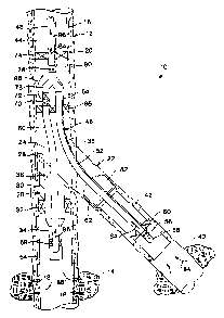
FIG. 1 depicts a well in which initial steps of the method 10 have been
performed. A parent wellbore 12 has been drilled and intersects a formation or
interval of a formation 14. As used herein, the term "formation" is used to
designate either a formation or a particular interval of a formation. Casing
16 is
installed in the parent wellbore 12 and cemented in place. Perforations 18 are
formed through the casing 16 and cement 20 to provide flowpaths for fluid
between the wellbore 12 and the formation 14.
The method 10 will be described herein as it may be utilized in
producing fluids from the well, such as by flowing fluid from the formation 14
to
CA 02521139 1998-09-02
8
the earth's surface through the wellbore 12. However, it is to be clearly
understood that a method performed according to the principles of the present
invention may also be utilized in injecting fluids into one or more formations
intersected by the well. Additionally, it will become readily apparent to one
of
ordinary skill in the art that a method performed according to the principles
of
the present invention may be utilized in simultaneously injecting fluids into
one
or more formations intersected by the well and producing fluids from one or
more formations intersected by the well.
In the method 10, a lateral wellbore 22 is to be drilled so that it intersects
the parent wellbore 12 at an intersection 24. For this purpose, a whipstock
assembly 26 is positioned in the parent wellbore 12 and oriented so that an
upper inclined deflection surface 28 formed on a generally tubular whipstock
30
is adjacent the intersection 24 and faces toward the lateral wellbore-to-be-
drilled 22. The whipstock assembly 26 is anchored to, and sealingly engaged
with, the casing 16 by means of a packer 32 attached to the whipstock 30. A
tailpipe 34 or other tubular member, such as a conventional PBR, is attached
to, and extends downwardly from, the packer 32. Alternatively, the tubular
member 34 may be a mandrel of the packer 32.
It is to be understood that the whipstock assembly 26 may include other
or different elements, or substitutions may be made for the representatively
illustrated elements thereof, without departing from the principles of the
present
invention. For example, the whipstock 30 may include an axial bore 36 which
CA 02521139 1998-09-02
9
is filled with a relatively easily drillable material. The tailpipe 34 may
have a
conventional plug installed therein prior to, and during, drilling of the
lateral wellbore
22. Various whipstock assemblies and procedures for drilling lateral
wellbores,
which may be utilized in the method 10, are disclosed in U.S. Patent No.
5,833,033
entitled APPARATUS FOR COMPLETING A SUBTERRANEAN WELL AND
ASSOCIATED METHODS OF USING SAME and filed July 15, 1996, and U.S.
Patent No. 5,884,704 entitled METHODS OF COMPLETING A SUBTERRANEAN
WELL AND ASSOCIATED APPARATUS and published on March 23, 1999.
With the whipstock assembly 26 positioned at the intersection 24, a series of
cutting tools (not shown) are utilized to form an opening 38 laterally through
the
casing 16 and cement 20. The lateral wellbore 22 is then drilled outwardly
from the
parent wellbore 12 to intersect a desired formation 40. The formation 40 may
be
separate and isolated from the formation 14, or the formations 14, 40 may be
portions
of the same formation, etc. For example, in a water flooding operation, water
may be
injected into the formation 14, resulting in production of hydrocarbon fluids
from the
formation 40.
A liner 42 or other tubular structure is lowered through an upper portion 44
of
the parent wellbore 12, through the opening 38, and into the lateral wellbore
22. The
liner 42 is then cemented in place. However, it is to be
CA 02521139 1998-09-02
10
understood that it is not necessary for the liner 42 to be installed in this
manner in the
method 10. For example, the liner 42 may extend upwardly through the opening 3
8,
across the intersection 24 and into the upper portion 44 of the parent
wellbore 12.
Referring additionally now to FIG. 2, an apparatus 46 is representatively and
schematically illustrated, which embodies principles of the present invention.
The
apparatus 46 is utilized in the method 10 for controlling the rate of fluid
flow into, or
out of, the formations 14, 40 intersected by the parent and lateral wellbores
I2, 22.
Although the apparatus 46 is depicted in FIG. 2 as it is completely assembled
when
installed in the well, it is to be understood that, in actual practice, the
apparatus 46
may be assembled as it is installed in the well, it may be assembled in the
well after
its individual elements have been installed therein in separate subassemblies,
etc.
The apparatus 46 includes three interconnected tubing strings 48, 50, 52.
When the apparatus 46 is installed in the well, the tubing string 48 extends
upwardly
to the earth's surface. The tubing strings 50, 52, which may also be referred
to as
tailpipes, extend downwardly from the tubing string 48. The tubing string 50
extends
into a lower portion 54 of the parent wellbore 12, and the tubing string 52
extends
into the lateral wellbore 22, when the apparatus 46 is installed in the well.
The tubing string 52 includes a conventional plug 56, a remotely controllable
flow regulating device 58, a packer or other sealing device 60 and
CA 02521139 1998-09-02
11
a releasable deflection device 62. The deflection device 62 radially outwardly
surrounds the packer 60, regulating device 58 and plug 56, and extends
somewhat downwardly therefrom. The deflection device 62 is utilized to direct
the tubing string 52 into the lateral wellbore 22 as the apparatus 46 is
lowered
into the well. It is configured so that it will deflect off of the deflection
surface
28 toward the lateral wellbore 22, rather than passing through the bore 36 of
the whipstock 30. The deflection device 62 releases for displacement relative
to the remainder of the tubing string 52 after deflecting off of the
deflection
surface 28. Such release of the deflection device 62 may be performed upon
receipt of a signal and/or fluid pressure on lines 64 interconnected thereto,
in
response to engagement with a structure in the lateral wellbore 22, in
response
to manipulation of the apparatus 46, or any other method. An apparatus which
may be used for the deflection device 62 in the method 10 is described more
fully hereinbelow in relation to FIGS. 6A-6B and 7A-7D.
The regulating device 58 may be a variable choke, which is responsive
to signals and/or fluid pressures, etc. carried by lines 64 coupled thereto.
Signals may be sent to the regulating device 58 by other methods, as well,
such as by acoustic telemetry, electromagnetic waves, magnetic fields, mud
pulses, etc. However, it is to be clearly understood that the regulating
device
58 may be otherwise controlled without departing from the principles of the
present invention, for example, by manipulation of a latching or shifting tool
engaged with the regulating device and conveyed on wireline, slickline,
CA 02521139 1998-09-02
12
segmented tubing, coiled tubing, etc., by otherwise mechanically controlling
the
regulating device, by operating the regulating device with a Downhole Power
Unit
available from Halliburton Energy Services, Inc.
Suitable regulating devices for use in the method 10 are described in U.S.
Patents No. 5,957,207 and No. 5,957,208 each of which is entitled FLOW
CONTROL APPARATUS FOR USE IN A SUBTERRANEAN WELL AND
ASSOCIATED METHODS, and each of which was filed July 21, 1997. Another
suitable regulating device is the SCRAMST"'' ICV (inflow choke valve)
available
from Petroleum Engineering Services, Ltd. of The Woodlands, Texas. As
representatively illustrated in FIG. 2, the regulating device 58 acts to
regulate the rate
of fluid flow through a sidewall portion of the tubing string 52, however, it
is to be
understood that the regulating device may alternatively regulate fluid flow
axially
therethrough, in which case the plug 56 may not be included in the tubing
string 52.
The packer 60 may be another sealing device, such as a packing stack, seal
element, etc. for sealing engagement with a seal surface, such as a PBR
(polished
bore receptacle) attached to the liner 42. A suitable packer for use in the
method 10
is the remotely settable SCRAMSTM HF (high flow) packer available from
Petroleum
Engineering Services, Ltd. This type of packer may be interconnected to the
lines 64
and set within the liner 42, or other tubular structure, in response to
signals and/or
fluid pressure, etc. carried by the lines 64. Alternatively, the packer 60 may
CA 02521139 1998-09-02
13
be a conventional hydraulically or mechanically settable packer having
provision for passing the lines 64 therethrough. If remotely settable, the
packer
60 may receive signals by acoustic telemetry, electromagnetic waves, mud
pulses, or any other communication means.
A dual string packer 66 sealingly engages the tubing strings 50, 52. If
the lines 64 are utilized to remotely control operation of the regulating
device
58, packer 60 and/or the deflection device 62, the packer 66 may include
provision for extending the lines 64 therethrough. The packer 66 is configured
for sealingly engaging the casing 16 in the upper portion 44 of the parent
wellbore 12 above the opening 38 when the apparatus 46 is installed in the
well. The packer 66 may be hydraulically or mechanically set, and may be
remotely set in response to signals and/or fluid pressures carried by the
lines
64.
The tubing string 50 includes a packing stack 68 or other sealing device,
a perforated sub 70 having openings formed radially therethrough and a plug
72. The packing 68 is configured for passing through the whipstock bore 36
and sealing engagement with the tailpipe 34. Alternatively, the packing 68 may
be a packer configured for setting within the tailpipe 34, and may be remotely
settable, as described above for the packer 60. It will be readily appreciated
by
a person of ordinary skill in the art that when the packing 68 is sealingly
engaged within the tailpipe 34, fluid may flow from the formation 14, into a
CA 02521139 1998-09-02
14
lower end of the tubing string 50, through the packer 66 and outward through
the
openings in the perforated sub 70.
The tubing string 48 includes a packer 74 or other sealing device and a
remotely controllable flow regulating device 76. The packer 74 may be similar
to the
packer 60, except that it is configured for setting within the upper portion
44 of the
parent wellbore 12. The regulating device 76 may be similar to the regulating
device
58, and may be controlled by any of the means described above for controlling
the
regulating device 58.
A coupling device 78 couples the tubing string 48 to the tailpipes 50, 52. The
coupling device 78 may be a conventional wye block and may include a vane or
other
member for directing tools, wirelines, coiled tubing, etc. from the tubing
string 48
into a selected one of the tailpipes 50, 52. Of course, if access is desired
to the
tailpipe 50, the plug 72 should be removed therefrom. A suitable wye block for
use
as the coupling device 78 in the method 10 is described in U.S. Patent No.
6,009,942
entitled WYE BLOCK HAVING A ROTARY GU>DE INCORPORATED
THEREIN, filed on June 10, 1997. Where such a directing member is included in
the
coupling device 78, it may be operated mechanically, hydraulically, in
response to
signals and/or fluid pressure carried by the lines 64, acoustic telemetry,
electromagnetic waves, mud pulses, etc. The coupling device 78 may be
controlled
by any of those means described above for the regulating device 58.
CA 02521139 1998-09-02
The regulating device 76 operates to regulate the rate of fluid flow
through a sidewall portion of the tubing string 48. In this way, fluid passing
outwardly through the openings in the perforated sub 70, and into an annulus
80 formed radially between the tubing string 48 and the parent wellbore 12
when the apparatus 46 is installed in the well, may flow into the tubing
string
48. Thus, as the apparatus 46 is representatively illustrated in FIG. 2, fluid
flowing between the tubing string 48 and the tailpipe 50 does not necessarily
flow through the coupling device 78. Instead, it flows into the annulus 80,
thereby bypassing the coupling device 78. Alternatively, the regulating device
76 may be included in the tailpipe 50, similar to the manner in which the
regulating device 58 is included in the tailpipe 52, in which case the plug 72
and perforated sub 70 would not be included in the tailpipe 50 and flow
between the tubing string 48 and the tailpipe 50 would pass through the
coupling device 78.
Referring additionally now to FIG. 3, the apparatus 46 is representatively
illustrated as it is operatively installed in the well. The deflection device
62 has
deflected the tailpipe 52 into the lateral wellbore 22 as the apparatus 46 was
lowered into the well. Thereafter, since the tailpipe 50 is shorter than the
tailpipe 52, the tailpipe 50 is inserted through the whipstock bore 36 and
into
the lower portion 54 of the parent wellbore 12. However, it is to be clearly
understood that it is not necessary for the tailpipe 50 to enter the lower
parent
wellbore 54 after the tailpipe 52 enters the lateral wellbore 22, or for the
tailpipe
CA 02521139 1998-09-02
16
50 to be shorter than the tailpipe 52, in keeping with the principles of the
present
invention.
The deflection device 62 has been released for axial displacement relative to
the remainder of the tailpipe 52 by engaging the deflection device with an
upper PBR
(polished bore receptacle) 82 attached to the liner 42 and applying an axially
downwardly directed force to the deflection device by manipulation of the
apparatus
46 from the earth's surface. As described above, however, release of the
deflection
device 62 may be accomplished by other methods without departing from the
principles of the present invention.
When the deflection device 62 is released, the tailpipe 52 extends further
into
the lateral wellbore 22. The packer 60, regulating device 58 and plug 56 enter
the
liner 42. When positioned therein as desired, the packer 60 is set so that it
sealingly
engages and anchors to the liner 42. The packer 60 may be set by any method,
as
described above.
It will be readily apparent to one of ordinary skill in the art that, with the
packer 60 set in the liner 42 as representatively illustrated in FIG. 3, fluid
(represented by arrows 84) may flow from the formation 40, inwardly through
the
regulating device 58, through the tailpipe 52, through the coupling device 78,
and
through the tubing string 48 to the earth's surface. Of course, if it is
desired to inject
the fluid into the formation 40, the fluid 84 may flow in the opposite
direction.
CA 02521139 1998-09-02
17
After the tailpipe 50 has been inserted into the lower parent wellbore 54,
the packing 68 sealingly engages the tubular member 34. If the packing 68 is
a packer, it is set within the tubular member 34. Thereafter, the packers 66
and 74 are set within the upper parent wellbore 44, so that they sealingly
engage and anchor to the casing 16. If the packers 60, 66, 68, 74 are remotely
settable, as described above, they may be sequentially set by transmitting an
appropriate signal to each of them and/or applying appropriate fluid pressure
to
each of them.
It will be readily apparent to one of ordinary skill in the art that, after
the
packers 66 and 74 are set and the sealing device 68 is sealingly engaged
within the tubular member 34, fluid (represented by arrows 86) may flow from
the formation 14, through the tailpipe 50, outward through the perforated sub
70, into the annulus 80, inward through the regulating device 76 and through
the tubing string 48 to the earth's surface. Of course, if an injection
operation
is to be performed, the fluid 86 may flow in an opposite direction. In the
method 10 as representatively illustrated in FIG. 3, the fluids 84, 86 are
commingled within the tubing string 48, but it is to be clearly understood
that
the fluids may be segregated from each other, without departing from the
principles of the present invention.
Thus has been described the method 10 and apparatus 46 which
permits the rate of flow of the fluids 84, 86 to be regulated in close
proximity to
the formations 14, 40. The rates of each fluid flow may be conveniently varied
CA 02521139 1998-09-02
18
as desired by remotely operating the regulating devices 76, 58. Additionally,
proportional flow rates of the fluids 84, 86 may be controlled to thereby vary
the
proportions of the fluids commingled in the tubing string 48.
Referring additionally now to FIGS. 4A-4B, another method 90
embodying principles of the present invention is representatively and
schematically illustrated. Elements of the method 90 which are similar to
those
previously described are indicated in FIGS. 4A-4B using the same reference
numbers, with an added suffix "a".
The method 90 differs from the method 10 in part in that a tailpipe 92
that extends into the lower parent wellbore 54a includes the packer 60a,
regulating device 58a and plug 56a, similar to that included in the tailpipe
52a
extending into the lateral wellbore 22a. The packer 60a is set in the tubular
member 34a. In this manner, the perforated sub 70, plug 72 and separate
annulus 80 are not utilized in the method 90. Thus, fluid 86a produced from
the formation 14a flows into the regulating device 58a below the packer 60a
and flows through the coupling device 78a into a tubing string 94, wherein the
fluids 84a and 86a are commingled.
As discussed above, it is not necessary for the fluids 84a and 86a to be
commingled. The packer 66a is shown in FIG. 4A in dashed lines to indicate
that it is not necessarily or preferably utilized in the method 90 as
representatively illustrated. However, it will be readily appreciated by a
person
of ordinary skill in the art that, if it is desired to segregate the fluids
84a and
CA 02521139 1998-09-02
19
86a from each other, the packer 66a may be installed and separate tubing
strings (not shown) coupled thereto and extended to the earth's surface, in
place of the coupling device 78a and tubing string 94. The packer 74a may be
utilized if commingled flow in the tubing string 94 is desired.
FIGS. 4A-4B also show that the method 90 may be utilized to control
fluid flow from additional wellbores and formations intersected by those
wellbores. For example, an additional lateral wellbore 96 may be drilled above
or below the lateral wellbore 22a extending outwardly from another opening
38a formed through the casing 16a and cement 20a, and intersecting another
formation 100. Another tailpipe 98 including another set of the packer 60a,
regulating device 58a and plug 56a may then be installed in a liner 42a in the
lateral wellbore 96.
Fluid (represented by arrows 102) may then be flowed from the
formation 100, inwardly through the regulating device 58a, and through the
tailpipe 98. The fluid 102 may be commingled with the fluids 84a and 86a in a
tubing string 104 extending to the earth's surface by providing another
coupling
device 78a interconnecting the tubing string 94, the tailpipe 98 and the
tubing
string 104. Alternatively, separate tubing strings may be provided for
segregating the fluids 102, 84a and 86a, or any combination of them, as
described above.
In FIGS. 4A-4B, the lateral wellbore 96 is depicted as being drilled
above the lateral wellbore 22a. For this purpose, another whipstock assembly
CA 02521139 1998-09-02
26a is positioned in the parent wellbore 12, with its deflection surface 28a
adjacent the intersection 24a of the parent wellbore and the upper lateral
wellbore 96. The upper lateral wellbore 96 is then drilled in a manner similar
to
that used to drill the lower lateral wellbore 22a.
The tubing string 94 is segmented, so that a lower portion 160 of the
tubing string 94 may be joined with an upper portion 162 thereof, after the
upper lateral wellbore 96 has been drilled. For this purpose, the lower
portion
160 includes a connector 164, which permits fluid communication between the
upper and lower portions 160, 162, and also interconnects the lines 64a. The
connector 164 may be of the type well known to those of ordinary skill in the
art
as a "wet connector". A suitable connector that may be used for the connector
164, with appropriate modification, is described in U.S. patent no. 5,577,925,
entitled CONCENTRIC WET CONNECTOR SYSTEM.
Alternatively, the lower portion 160 may include a PBR at its upper end
and the upper portion 162 may include an appropriate sealing device, such as
a packing stack, at its lower end for sealing engagement with the PBR. In that
case, interconnection of the lines 64a may be accomplished by one or more
other conventional connectors. However, it is to be clearly understood that
connection of the upper and lower portions 160, 162 of the tubing string 94
may be accomplished by any other means without departing from the principles
of the present invention. For example, the tubular member 34a included in the
upper whipstock assembly 26a could sealingly engage a PBR attached to the
CA 02521139 1998-09-02
21
upper end of the lower portion 160, so that when the packer 60a is set in the
tubular member, the upper portion 162 is in fluid communication with the lower
portion 160.
With the lateral wellbore 96 drilled as described above, the tailpipe 98,
upper portion 162 and tubing string 104 are installed in the well. The
tailpipe
98 may be deflected to enter the lateral wellbore 96 utilizing a deflection
device, such as the deflection device 62a, or other means may be utilized to
insert the tailpipe into the lateral wellbore. The upper portion 162 is
inserted
through the upper whipstock assembly 26a and connected to the lower portion
160. The packers 60a on the upper portion 162 and tailpipe 98 are set in the
tubular member 34a and liner 42a, respectively. Fluids 84a, 86a and 102 may
then be regulated to flow at desired rates of each into the tubing string 104
and
therethrough to the earth's surface.
Referring additionally now to FIG. 5, another method 110 embodying
principles of the present invention is representatively and schematically
illustrated. Elements of the method 110 which are similar to those previously
described are indicated in FIG. 5 using the same reference number, with an
added suffix "b". The method 110 differs in substantial part from the previous
methods 10, 90 in that a single tubing string 112 is utilized to regulate
fluid flow
from, or into, multiple formations 14b, 40b.
In the method 110, a liner 114 is installed extending into the lateral
wellbore 22b, and remains partially received within the upper parent wellbore
CA 02521139 1998-09-02
22
44b. The liner 114 is cemented in place overlying the whipstock assembly 26b.
Thereafter, an opening 116 is cut through a sidewall portion of the liner 114
to
provide access to the lower parent wellbore 54b via the whipstock bore 36b.
The tubing string 112 includes two regulating devices 76b, 58b and two
packers 74b, 60b. As representatively illustrated in FIG. 5, the regulating
device 76b is interconnected between the packer 74b and the packer 60b, and
the packer 60b is interconnected between the regulating device 76b and the
regulating device 58b. However, it will be readily appreciated by a person of
ordinary skill in the art that, for example, if a regulating device capable of
regulating fluid flow axially therethrough is utilized in place of the
regulating
device 58b, it could be positioned between the packers 74b, 60b, and the plug
56b could be eliminated from the tubing string 112. Thus, other configurations
of the tubing string 112 may be utilized without departing from the principles
of
the present invention.
The tubing string 112 is inserted through the opening 116, so that a
lower portion thereof extends into the lower parent wellbore 54b. The packer
60b is set within the tubular member 34b and the packer 74b is set within the
casing 16b in the upper parent wellbore 44b. As described above, if the
packers 74b, 60b are remotely settable, they may be set sequentially and
controlled from the earth's surface.
With the packers 74b, 60b set, the fluid 86b may flow from the formation
14b, inwardly through the regulating device 58b, and through the tubing string
CA 02521139 1998-09-02
23
112 to the earth's surface. The fluid 84b may flow from the formation 40b,
through the liner 114, inwardly through the regulating device 76b, and through
the tubing string 112 to the earth's surface, commingled with the fluid 86b.
The
regulating devices 76b, 58b may, thus, be utilized to independently regulate
the rate of each of these fluid flows, and to control the proportions of the
fluids
84b, 86b produced from the formations 14b, 40b. Of course, the flows of either
or both of the fluids 84b, 86b may be reversed in an injection operation.
Referring additionally now to FIGS. 6A-6B, a deflection device 120
embodying principles of the present invention is representatively illustrated.
The deflection device 120 may be utilized for the deflection device 62 in any
of
the methods described above wherein a deflection device is used. As
described herein, the deflection device 120 is releasable upon engagement
with a tubular structure and application of an axial force thereto, but it is
to be
clearly understood that the deflection device may be hydraulically,
electrically,
remotely, etc. released, without departing from the principles of the present
invention.
The deflection device 120 is shown in FIGS. 6A-6B in a configuration in
which it is run into a well. It includes an engagement portion 122, one or
more
release members 124, a blocking device 126, an inner generally tubular
mandrel 128 and an outer generally tubular housing 130. The outer housing
130 is shown radially outwardly surrounding a representative item of
equipment, a packer 132, but it is to be clearly understood that the housing
CA 02521139 1998-09-02
24
may overlie any item of equipment, or any combination of equipment desired,
with appropriate modification to the housing.
The packer 132 is threadedly attached to the inner mandrel 128, and the
inner mandrel is threadedly attached to a tubing string 134 extending upwardly
therefrom. As depicted in FIGS. 6A-6B, the inner mandrel 128 is prevented
from displacing axially relative to the housing 130, release members 124 and
engagement portion 122 by the blocking member 126. The blocking member
126 is representatively a generally C-shaped member which is radially
outwardly disposed to engage a sleeve 136 threadedly attached to the housing
130. The blocking member 126 is retained on the inner mandrel 128 by a
retainer 138 threadedly attached to the inner mandrel. Thus, with the blocking
member 126 disposed between and contacting the retainer 138 and sleeve
136, the inner mandrel 128 is prevented from displacing downwardly relative to
the housing 130. Additionally, the inner mandrel 128 is shouldered up against
a lower portion of the sleeve 136, thereby preventing the inner mandrel from
displacing upwardly relative to the housing 130.
The housing 130 is configured so that it will deflect off of a deflection
surface, such as the deflection surface 28. For this purpose, for example, the
housing 130 may have a larger diameter than the bore 36 of the whipstock 30,
or may be otherwise shaped to prevent its insertion through another member.
The housing is threadedly attached to the release members 124, sleeve 136
and engagement portion 122 (the engagement portion and release members
CA 02521139 1998-09-02
being integrally formed as shown in FIG. 6A), thereby making up an outer
assembly 140.
Preferably, the housing 130 extends downwardly past any items of
equipment attached below the inner mandrel 128. In this manner, the housing
130 will contact any structure, such as a whipstock, prior to the equipment,
and
will permit the deflection device 120 to direct the tubing string 122 toward,
for
example, a lateral wellbore. Fig. 6B shows an end cap 142 of the housing 130
through which an end sub 144 of the packer 132 extends, but it is to be
understood that, when the deflection device 120 is utilized in the methods
described above, it is preferred that the end cap 142 completely overlie any
item of equipment connected below the inner mandrel 128.
The release members 124 are axially elongated and circumferentially
spaced apart, so that they are resilient, that is, they may be radially
inwardly
deflected. Note that a radially inwardly extending projection 146 formed on
each release member 124 is in radial contact with the blocking member 126.
Thus, it will be readily appreciated that if the release members 124 are
radially
inwardly deflected, the blocking member 126 will also be radially inwardly
displaced thereby, and the inner mandrel 128 will no longer be secured by the
blocking member relative to the outer assembly 140. However, one or more
shear pins 148 installed through the sleeve 136 and into the mandrel 128 will
still releasably secure the inner mandrel 128 against axial displacement
relative
to the outer assembly 140.
CA 02521139 1998-09-02
26
The release members 124 also have radially outwardly extending
projections 150 formed thereon. The projections 150 extend radially outwardly
so that, when the deflection device 120 is inserted within an appropriate
tubular
structure, the projections 150 will engage the tubular structure and be
deflected
radially inward thereby. In the representatively illustrated embodiment of the
deflection device 120, the projections 150 are configured to permit radially
inward deflection of the release members 124 upon insertion of the deflection
device 120 into a PBR attached to a liner in a lateral wellbore. It is to be
clearly
understood, however, that the release members 124 may be otherwise
configured for engagement with other structures, without departing from the
principles of the present invention.
The engagement portion 122 is configured to engage the top of the PBR
attached to the liner and prevent further insertion of the deflection device
120
into the liner. For this purpose, the engagement portion 122 has a radially
outwardly extending flange 152 formed thereon, which has a greater diameter
than the inner diameter of the liner PBR. However, it is to be clearly
understood that the engagement portion 122 may be otherwise configured to
engage a structure, without departing from the principles of the present
invention.
Referring additionally now to FIGS. 7A-7D, the deflection device 120 is
representatively illustrated inserted into a PBR 154 attached to a liner 156.
The PBR 154 and liner 156 may, for example, correspond to the PBR 82 and
CA 02521139 1998-09-02
27
liner 42 of the method 10 as depicted in FIG. 3. The release members 124
have been radially inwardly deflected by radial contact between the
projections
150 and the inner diameter of the PBR 154. Such deflection of the release
members 124 has caused the projections 146 to radially inwardly displace the
blocking member 126. Thus, when the deflection device 120 is inserted into
the PBR 154, the blocking member 126 no longer secures the inner mandrel
128 against displacement relative to the outer assembly 140.
Thereafter, an axially downwardly directed force may be applied to the
inner mandrel 128 to shear the shear pins 148 and permit the inner mandrel
and any equipment 132 attached thereto to downwardly displace relative to the
outer assembly 140. Such downwardly directed force may be applied by
slacking off on the tubing string 134 at the earth's surface. An opposing
force
is applied to the outer assembly 140 by engagement of the engagement
portion 122 with the top of the PBR 154, the flange 152 thereby preventing
further downward displacement of the outer assembly 140. The packer 132 is
now permitted to displace downwardly into the liner 156 and may be set
therein, with the outer assembly 140 remaining within the PBR 154.
Of course, a person of ordinary skill in the art would find it obvious to
make certain modifications, additions, deletions, substitutions and other
changes to the various apparatus and methods described herein. Accordingly,
the foregoing detailed description is to be clearly understood as being given
by
CA 02521139 1998-09-02
28
way of illustration and example only, the spirit and scope of the present
invention being limited solely by the appended claims.