Note: Descriptions are shown in the official language in which they were submitted.
CA 02521187 2005-09-23
CONVEYOR FOR A WINDROWER
This invention relates to a swather otherwise known as a windrower
and particularly to a conveyor arrangement which conveys the crop swath or
windrow to one side of the frame for double windrawing. The term swather as
used
herein is synonymous with windrawer and can include many different types of
cutting
systems such as sickle knife and disk cutters, many different types of crop
converging systems including draper and auger and many different types of
conditioning systems including nip rollers and flail rollers.
BACKGROUND OF THE INVENTION
It is well-known that self propelled swathers include a tractor in the
form of a tractor frame carried on a pair of widely spaced front driven ground
wheels
together with widely spaced rear costar wheels. At the front of the frame is
mounted
a header extending across the frame for cutting the standing crop with the
header
generally having components which convey the crop material inwardly to a
discharge opening between the front wheels so that the crop material is
discharged
in a windrow or swath between the wheels of the tractor.
In some cases the tractor carries a set of conditioning rollers behind
the discharge opening far the crop material to be crushed or other4vise
conditioned
from improved drying action.
~0 It is becoming more popular to utilize a conveyor underneath the frame
of the tractor which acts, when activated, to transport the windrow from a
position
underneath the frame to a position of one side of the frame so that the
windrow can
be combined with another window or mare than one windrow where other windrows
CA 02521187 2005-09-23
2
are arranged alongside one another to be picked up simultaneously either for
collection in a forage harvesting system or for baling.
A number of different arrangements are known for this conveyor which
is also commonly known as a "double windrow attachment° or "DWA".
In US Patents 5,031,393 (Rostoucher) issued July 18, 1995; 5,351,468
(Pominville) issued October 4, 1984; 6,145,289 (Welsch) issued November 14,
2000
and f,679,038 (UValch) issued January 20, 2004 are provided designs of double
windrow attachment for windrowers which allow movements generally upwardly and
downwardly fnam a lowered operating position to a raised retracted position.
In US Patent 0,415,590 (Lohrentz) issued July 9, 2002 is shown a self
propelled windrower where the Conveyor has a fixed rear beam along a rear edge
of
the upper run of the belt and pivots about this fixed beam so that the front
edge of
the belt pivots upwardly and fonNardly from a lowered operating position in
which the
belt is inclined forwardly and downwardly to a raised retracted position.
Another arrangement mounted on a self-propelled tractor is shown in
drawings of a device manufactured by Assignee of the present application in
which
the conveyor does not pivot about a fixed axis but instead is mounted an links
which
allow the whole conveyor to move upwardly and forwardly from the lowered
operating position to a raised position. This design is based upon a previous
2p arrangement manufactured by Sharp's Welding and Mechanical Works in
Stanfield,
Arizona. The Sharp's device is also shown in photographs.
It is highly desirable that the conveyor be movable from an operating
position in which the conveyor belt is inclined forwardly and downwardly and
extends
CA 02521187 2005-09-23
across the frame to a retracted position in which the conveyor is removed from
the
path of the crop material. Hov~ver this movement is seriously constrained by
the
construction of tractor in that the conveyor in both positions must be clear
of the
wheels and must move to a properly retracted position and to a properly
located
operating position.
SUMMARY OF THE INVENTION
It is one object of the invention to provide an improved swather which
includes a swath conveyer which is effectively moveable between a raised
storage
position and an operating position.
According to one aspect of the invention there is provided a swather
comprising:
a tractor having a frame;
ground wheels for supporting the frame for mover gent across the
ground including two front ground wheels spaced apart to define an open width
underneath the tractor and between the front wheels and two rear ground wheels
spaced apart to define an open width underneath the tractor and between the
rear
wheels;
a header for attachment across a front of the tractor for cutting a
standing crop as the tractor moves over the ground;
21a the header having a converging system far converging the Cut crop
inwardly from ends of the header toward a discharge at a central area of the
header;
the discharge of the header being arranged between the front wheels
such that crop discharged from the header passes through the open width
between
CA 02521187 2005-09-23
the front wheels to be discharged onto the ground in a swath as the tractor
moves
farwardly and the standing crop is cut;
and a swath conveyor located underneath the frame and arranged to
receive cut crop from the discharge and far conveying the cut crop across the
frame
to a first discharge side of the frame for discharge to an associated first
side of the
tractor;
the swath conveyor comprising an endless belt mounted an guide
rollers including a first guide taller on the first side of the frame and a
second guide
roller on a send side of the frame opposite the first side such that crap
falling an
an upper run of the belt is carried by that upper run transversely of the
frame from a
position rearward of the discharge toward the first guide roller to said one
side of the
frame;
a mounting assembly mounting the swath conveyor far movement
relative to the frame between:
a raised storage position in which the upper run and the guide rollers
therefor are generally horizontal underneath the frame;
and a lowered operating position in which the upper run of the belt is
inclined by the first and second guide rollers from an upperJrear edge
farwardly and
downwardly to a lowerlfront edge such that the crop from the discharge lands
an the
upper run between the upperlrear edge and the lowerlfront edge to be carried
transversely to said one side of the frame;
the mounting assembly being arranged such that the lowerlfront edge
of the upper run at the second guide roller is, as the swath conveyer is moved
from
CA 02521187 2005-09-23
the raised position to the towered position, moved forwardly by the mounting
assembly relative to the lowerlfront edge of the upper run at the first guide
roller.
The discharge of the header is in most cases provided by the
conditioner rollers behind the converging system and the crop is transferred
from the
8 conditioner rolls to the conveyor. However the use of conditioner rolls or
some other
form of conditioner is not essential and in this situation the discharge may
be formed
by some other element which ensures transfer to the conveyor.
Preferably the mounting assembly is arranged such that bath the
lowerlfront edge of the upper run at the second guide roller and the
lowerlfront edge
of the upper run at the first guide roller are moved fonnrardly as the swath
conveyer
is moved from the raised position to the lowered position.
Preferably the mounting assembly is arranged such that the lowerlfront
edge of the upper run at the second guide roller is moved in the lowered
position to
a position between the front wheels.
Preferably the mounting assembly is adjustable such that the amount
of forward movement of the lowerlfront edge of the upper run at the seGOnd
guide
roller is adjustable.
Preferably the mounting assembly is adjustable between two
selectable arrangements such that the amount of forward movement of the
~0 lowerlfrant edge of the upper run at the second guide roller is adjustable
between
two separate positions.
Preferably the mounting assembly comprises a transverse rear beam
carried on a linkage by which the beam is raised upwardly and rearwardly from
the
CA 02521187 2005-09-23
lowered position to the raised position while the beam is rotated about an
axis
longitudinal of the beam.
Preferably the linkage includes a lift arm mounted on the frame and a
pivot coupling at a forward end of the lift arm allowing pivotal movement of
the beam
relative to the forward end of the lift arm to allow the forward movement of
the
fowerlfront edge of the upper run at the second guide roller.
Preferably there is provided a steering Ilnk Connected to the beam for
causing the pivotal movement of the beam.
According to a second aspect of the invention there is provided a
swather comprising:
a tractor having a frame;
ground wheels for supporting the frame for movement across the
ground including two front ground wheels spaced apart to define an open width
underneath the tractor and between the front wheels and two rear ground wheels
spaced apart to define an open width underneath the tractor and between the
rear
wheels;
a header for attachment across a front of the tractor for cutting a
standing crop as the tractor moves over the ground;
the header having a converging system for converging the cut crop
inwardly from ends of the header toward a discharge at a central area of the
header;
the discharge of the header being arranged between the front wheels
such that crop discharged from the header passes through the open width
between
the front wheels to be discharged onto the ground in a swath as the tractor
moves
CA 02521187 2005-09-23
7
farwardly and the standing crop is cut;
and a swath conveyor located underneath the frame and arranged to
receive cut crop from the discharge and far conveying the cut crop across the
frame
to a first discharge side of the frame for discharge to an associated first
side of the
tractor;
the swath conveyor comprising an endless belt mounted an guide
rollers including a first guide taller on the first side of the frame and a
second guide
roller an a second side of the frame opposite the first side such that crop
falling on
an upper run of the belt is carried by that upper run transversely of the
frame from a
1 ~ position rearward of the discharge toward the first guide roller to said
one side of the
frame;
a mounting assembiy mounting the swath conveyor far movement
relative to the frame between:
a raised storage position in which the upper run and the guide rollers
therefor are generally horizontal underneath the frame;
and a lowered operating position in which the upper run of the belt is
inclined by the first and second guide rollers from an upperlrear edge
farwardly and
downwardiy to a lowerlfrant edge such that the crop from the discharge lands
on the
upper run between the upperlrear edge and the lawerlfront edge to be carried
transversely to said one side of the frame;
the mounting assembly being arranged such that both the lowerlfront
edge of the upper run at the second guide caller and the lawerlfrant edge of
the
upper run at the first guide roller are moved forwardly 2~s the swath conveyer
is
CA 02521187 2005-09-23
moved from the raised position to the lowered position.
According to a third aspect of the invention there is provided a swather
comprising:
a tractor having a frame;
ground wheels for supporting the frame for movement across the
ground including two front ground wheels spaced spark to define an open width
underneath the tractor and between the front wheels and two rear ground wheels
spaced apart to define an open width underneath the tractor and between the
rear
wheels;
a header for attachment across a front of the tractor for cutting a
standing crop as the tractor maven over the ground;
the header having a converging system for converging the cut crop
inwardly from ends of the header toward a discharge at a central area of the
header;
the discharge of the header being arranged between the front wheels
such that crap discharged from the header passes through the open width
between
the front wheels to be discharged onto the ground in a swath as the tractor
moves
forwardly and the standing crop is cut;
and a swath conveyor located underneath the frame and arranged to
receive cut crop from the discharge and for conveying the cut crop across the
frame
to a first discharge side of the frame for discharge to an associated first
side of the
tractor;
the swath conveyor comprising an endless belt mounted on guide
rollers including a first guide roller on the first side of the frame and a
second guide
CA 02521187 2005-09-23
roller on a second side of the frame opposite the first side such that crop
falling on
an upper run of the belt is carried by that upper run transversely of the
frame from a
position rearward of the discharge toward the first guide roller to said one
side of the
frame;
a mounting assembly mounting the swath conveyor for movement
relative to the frame between:
a raised storage position in which the upper run and the guide rollers
therefor are generally horizontal underneath the frame;
and a lowered operating position in which the upper run of the belt is
~0 inclined by the first and second guide rollers from an upperlrear edge
forwardly and
downwardiy to a lowerlfront edge such that the crop from the discharge lands
on the
upper run between the upperlrear edge and the Iowerffront edge to be carried
transversely to said one side of the frame;
the mounting assembly comprises a transverse rear beam carried on a
linkage by which the beam is raised upwardly and rearwardly from the lowered
position to the raised position while the beam is rotated about an axis
longitudinal of
the beam;
and wherein the linkage includes a lift arm mounted on the frame and a
pivot coupling at a forward end of the lift arm allowing pivotal movement of
the beam
relative to the forward end of the lift arm to allow the forward movement of
the
lowerlfront edge of the upper run at the second guide roller.
BRIEF DES~RIPTI~N GF THE DRAWINGS
One embodiment of the invention will now be described in conjunction
CA 02521187 2005-09-23
with the accompanying drawings in which:
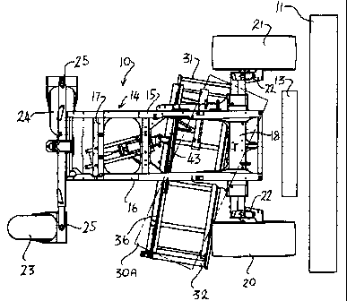
Figure 1 is a top plan view partly in phantom showing a self-propelled
windrower according to the present invention including a~ double windrow
attachment
in the form of a conveyor where the conveyor is shown in the lowered operating
position. A second lowered operating position is shown also in phantom.
Figure 2 is a top plan view of the same components as Figure 1
showing the conveyor in the raised retracted position.
Figure 3 is a side elevational view of some components of the
windrower of Figures 1 and 2 with other components removed for convenience of
illustration and showing the conveyor in the lowered operating position.
Figure 4 is a similar side elevational view to that of Figure 3 but
showing only the conveyor Itself in the. raised storage position.
Figure 5 is an isometric view of the conveyor of Figure 4 again showing
the conveyor in the lowered operating position.
Figure 6 is an isometric view showing the elements of Figure 5 but
shown in the raised retracted position.
Figure 7 is an isometric view showing the elements of Figure 5 but
shown from the opposite side.
In the drawings like characters of reference indicate corresponding
parts in the different figures.
DETAILED DESCRIPTIaN
In the Figures is shown a swather or windrower which comprises a
tractor 10, a header 11 and a crop conditioner 13. The header and crop
conditioner
CA 02521187 2005-09-23
11
are shown only schematically since these are well known to one skilled in the
art and
various differeryt arrangements, locations and type can be provided. In most
cases a
conditioner is used in arrangements where a double windrow attachment is
required
but the conditioner is not essential provided the crop is transferred by some
construction from the discharge to the belt described hereinafter.
The tractor 10 is also of a conventional nature and many different
arrangements are well known to one skilled in the art. Basically a tractor of
this type
includes a frame 94 defined by a pair of longitudinally extending parallel
rails 15 and
16 connected by suitable cross members 17 together with a front axle 18 and a
rear
axle 19. The front axle carries a pair of driven wheels 20 and 21 which are
generally
driven by hydraulic motors (not shown) supplied with hydraulic fluid under
pressure
from pumps (not shown) driven by a engine (also not shown) mounted on the
frame.
The rear axle carries a pair of castor wheels 23 2nd 24. Steering is effected
by
controlling the differential in speed between the wheels 2~ and 21 as driven
by the
i 5 motors. The Castor wheels are mounted on castor pins 25 carried on the
axle and
so the castor wheels can rotate fully around the castor pins and thus require
significant amount of space around the outer ends of the rear axle 19
including an
area underneath the frame.
The frame is supported at a height well above the ground so as to
provide crop clearance. The header 11 is mounted on front arms of the frame
which
are again not shown as these can vary in accordance well the requirements of
one
skilled in the art.
The header is of the type which cuts standing crop as the tractor
CA 02521187 2005-09-23
~2
moves across the field and converges the cut crop into a discharge opening
between the front wheels 20 and 21. If a conditioner is provided, the crop
material
from the discharge of the header passes through the conditioner and is
discharged
rearwardly from the conditioner between the front wheels sa that the crop
material
Can be deposited as a windrow underneath the tractor and between the wheels.
In some cases it is desirable to provide a crop conveyor which acts as
a double windrow attachment, Such devices are generally known and comprise a
conveyor in the form of a belt carried on end guide rollers so that the run of
the belt
is presented underneath the tractor to receive the crop material from the
conditioner.
The belt conveyor carries the crop material outwardly to one side beyond the
wheels
so that the crop material in the windrow can be deposited outside the width of
the
tractor along one side rather then between the wheels.
Thus in the present arrangement, the crop conveyor is generally
indicated at 30 which includes a first guide roller 32 on one side of the
frame and a
second guide roller 31 on the opposite side of the frame. The toiler 3~ is
driven by 2~
motor 33 so as to carry an endless belt which is wrapped around the rollers to
define
an upper run 34 of the belt which extends across the frame for transporting
the crop
material. The roller 31 is mounted just behind the discharge so as to collect
the crop
material at the side of the discharge and the roller 32 is located outwardly
beyond
the wheel 20. The rollers 31 and 32 are mounted on suitable support frames
including a front rail 35 and a rear rail 36 together with a series of cross
members
37. The rear rail 36 as best shown in figure ~ is in the form of a main
tubular beam
which extends across the rear and provides support for the remainder of the
CA 02521187 2005-09-23
conveyor which extends forwardly therefrom in cantilever manner so that the
cross
members 3T are r,,arried an the beam 36 which in turn supports the front rail
35 and
the guide rollers 31 and 32,
The crop conveyor is carried on a mounting assembly generally
indicated at 40 which is attached between a support member 41 of the frame and
the beam 3fi.
In general the mounting arrangement 40 is arranged to move the
conveyor from a raised retracted position as Shawn in Figures 2, 4 and fi and
a
lowered operating position as shown in Figures 1, 3, 5 and 7. By comparing the
positions shown in Figures 1 and 2, it will be noted that the raised retracted
position
supports the beam 36 so that is extends substantially horizontally across the
frame
at a rearward retracted position. The beam 36 as best shown in Figure 6 is
raised
up immediately under the frame support member 41 and the beam is twisted so as
to raise the conveyor and particularly the front edge of the conveyor and the
front
edge of the upper run of the belt to a position just underneath the frame.
Thus the
conveyor is raised to a position which is as high as possible under the frame
and is
clear of the normal path of the crop material which is discharged between the
wheels
and underneath the frame so that in the raised retracted position the aop
material
can continue on its normal path between the wheels under the frame to be laid
as a
windrow behind the tractor.
In the forward operating position shown in Figure 1, the beam 35 is
moved forwanily but at the same time the beam is twisted in two directions. In
the
first direotian, the beam is twisted about its axis so as to lower the front
edge of the
CA 02521187 2005-09-23
94
conveyor so that the conveyor is inclined upwardly and rearwardly as best
shown in
Figure 3, Thus in Figure 3 the front edge of the belt is indicated at 34A
which is
below the rear edge of the belt indicated at 348. The bait is thus inclined
upwardly
and reanrvardly so the crop material can be deposited ants the belt.
In addition the beam 36 is rotated about a vertical mounting pivot 43 so
that the second guide roller 31 and the associated end of the belt is moved
forwardly
relative to the first guide roller 32. Thus the conveyor twists so that the
end of the
belt at the second guide roller 31 is moved forwardly to move it to a position
between
the wheels and closer to the conditioner rolls.
Yet further the mounting 40 moves the whole of the beam 36 forwardly
so the both ends of the front edge of the belt are moved forwardly. This moves
the
first guide roller 32 to a position just behind the wheel 20, as close as
possible to the
wheel 20 without causing interference, At the same time the second guide
roller 31
and the associated end of the belt is moved further forward into a position
between
the wheels 20 and 21 that is inwardly of the wheel 21, In this way the front
edge of
the belt at the second guide roller 31 is located farwardly of the rear edge
of the
wheel 21 and into the area under the axle so as to better receive the crop
material
from the discharge at the conditioner 13.
Thus the crop is turned at an angle in the order of seventy degrees
across the tractor to the discharge at the side of the tractor, that is the
conveyor is
arranged at an angle of 20 degrees to a line transverse to the tractor. To
ensure
that crop does not fall over the rear edge of the conveyor belt, a back plate
42 is
provided fixed to the rear edge of the conveyor at the bes~m 3fi and then
standing
CA 02521187 2005-09-23
'~ rJ
upwardly therefrom. The plate is arranged so that it is directed behind the
discharge
so that crop material discharging at the upper extreme of the discharge
engages
onto the plate, drops onto the Conveyor and is conveyed at the diagonal angle
to the
discharge of the conveyor.
The mounting as described hereinafter also is arranged to provide two
set positions of the conveyor, The first position is shown in full line and
the second
position is shown in phantom as indicated at 30A. In this position, the angle
of twist
of the beam about a generally upright axis is increased so that the edge of
the
conveyor belt at the roller 31 is moved yet further forward and the edge of
the
conveyor at the roller 32 is moved rearwatdly. This yet further increases the
angle
of inclination of the conveyor across the tractor up to an angle of the order
of sixty
degrees, or thirty degrees to a transverse line. This moves the front edge of
the
conveyor at the end defined by the roller 31 yet further forward behind the
discharge
of the header and this position is particularly useful for different
arrangements of
'15 header where the discharge is moved forwardly to ensure that crop material
does
not fall between the discharge and the forward edge of the conveyor.
The mounting 4t7 as best shown in Figures 5 and 7 comprises a lift arm
45 mounted on a pivot 46 attached to the support bracket 41 carried on the
frame.
The support bracket is generally horizontal and defined by a channel member
with
the pin 4f extending across the channel member. The lift arm 45 is also
defined by
a channel member extending across the pin so that it pivots about the pin and
provides mechanical support. The lift arm is raised and lowered by a cylinder
47. In
an extended position of the cylinder, the lift arm 45 is moved downwardly so
that
CA 02521187 2005-09-23
lower end 48 of the lift arm is below the pivot pin 46. The lift arm carries a
support
arm 48 which projects forwardly from the lower end 48 and is carried on a
pivot pin
50. At the forward end of the support arm is provided a bracket 51 which
attaches to
the beam 38. The bracket 51 includes a first portion 52 atkached to the arm 49
and
the second pivot portion 53 which can pivot relative to the first portion
about a pivot
pin 54. This pivot pin allows the pivot portion 53 and the beam 3~ to which it
is
attached to pivot side to side about a generally upright axis 54A defined by
the pin
54.
A guide arm 55 extends from the fonnrard end of the support arm 48 up
to the bracket 46 and is attached thereto by a pin 56. The guide arm 55 thus
controls the angle of the support arm 49 relative to the horizontal as the
lift arm 45
pivots forwardly and rearwardly.
Thus, as can be seen by comparing Figures 4 and 5, when the lift arm
45 is pivoted, by the retraction of the cylinder 47 upwardly and rearwardly,
this acts
to raise the support arm 49 and also to pivot the support arm and the beam
carried
thereby in a counter clockwise direction. Thus in the extended position shown
in
Figure 5 the arm 49 extends forwar~dly and downwardly and the conveyor 30
extends
forwardly and downwardly from the forward end of the support arm 49 in the
required angle as previously described.
In the retracted position shown in Figure 4, the arm is pivoted in a
counter clockwise direction so that the conveyor 30 is also pivoted in the
counter
clockwise direction and raised up closely under the frame and under the
bracket 41.
A steering link 57 of fixed length is connected between the beams 36
CA 02521187 2005-09-23
at a clevis 58 and the lift arm 45 at a clevis 59 adjacent the lower end of
the lift arm.
This link is arranged so the geometry of the system causes the link to guide
pivotal
movement of the beam 3B around the pin 54 so as to pivot the end of the
conveyor
at the roller 31 forwardly to a greater extent than the opposite end of the
conveyor as
the whole of the conveyor is carried forwardly by the brackEt 51.
A second steering link fi0 is connected between the shield 42 and the
bracket 41. The steering link 60 acts to fold the shield downwardly and
forwardfy as
can be seen by comparing Figures 5 and 6.
The length andlor position of fhe steering links 57 and SIB can be
adjusted so as to change the movement of the conveyor between the two separate
positions shaven in Figure 1. The angle of the pin 54~ to a vertical plane
longitudinally
of the tractor and thus the angle of the pivot axis 54A to the vertical can be
adjusted,
as best shown in Figure 7, by releasing bolts 54B and twisting the second
pivot
portion 53 relative to the bracket portion 52 at the forward end of the arm
49. This
change in angle oaf the axis 54A changes the inclination of the conveyor belt
as it
extends across the tractor thus raising or lowering the outer end of the
conveyor at
the first guide roller 32,
It will be appreciated that the mounting arrangement is only one
example of a number of mounting arrangements which can provide the mechanical
2p movement described above and that other arrangements will be apparent to
one
skilled In the art from analysis of the movements required.
Since various modifications can be made in my invention as herein
above described, and many apparently widely different embodiments of same made
CA 02521187 2005-09-23
within the spirit and scope of the claims without department from such spirit
and
scope, it is intended that aH matter contained in the accompanying
specification shall
be interpreted as illustr2~tive only and not in a limiting sense.