Note: Descriptions are shown in the official language in which they were submitted.
CA 02521705 2005-10-06
WO 2004/090173 PCT/AU2004/000472
1
DIRECT SMELTING PLANT
TECHNICAL FIELD
The present invention relates to a direct
smelting plant for producing molten metal from a
metalliferous feed material such as ores, partly reduced
ores and metal-containing waste streams.
A known direct smelting process, which relies
principally on a molten bath as a reaction medium, and is
generally referred to as,the Hlsmelt process, is described
in International Application PCT/AU96/00197 (WO 96/31627)
in the name of the applicant.
The Hlsmelt process as described in the
International application in the context of producing
molten iron includes:
(a) forming a bath of molten iron and slag in a
vessel;
(b) injecting into the bath:
(i) a metalliferous feed material,
typically iron oxides; and
(ii) a solid carbonaceous material,
typically coal, which acts as a
reductant of the iron oxides and a
source of energy; and
(c) smelting metalliferous feed material to iron
in the metal layer.
The term "smelting" is herein understood to mean
thermal processing wherein chemical reactions that reduce
CA 02521705 2005-10-06
WO 2004/090173 PCT/AU2004/000472
2
metal oxides take place to produce molten metal.
The Hlsmelt process also includes post-combusting
reaction gases, such as CO and H2 released from the bath,
in the space above the bath with o2mygen-containing gas and
transferring the heat generated by the post-combustion to
the bath to contribute to the thermal energy required to
smelt the metalliferous feed materials.
The Hlsmelt process also includes forming a
transition zone above the nominal quiescent surface of the
bath in which there is a favourable mass of ascending and
thereafter descending droplets or splashes or streams of
molten metal and/or slag which provide an effective medium
to transfer to the bath the thermal energy generated by
post-combusting reaction gases above the bath.
In the Hlsmelt process the metalliferous feed
material and solid carbonaceous material is injected into
the molten bath through a number of lances/tuyeres which
are inclined to the vertical so as to extend downwardly and
inwardly through the side wall of the smelting vessel and
into a lower region of the vessel so as to deliver at least
part of the solids material into the metal layer in the
bottom of the vessel. To promote the post-combustion of
reaction gases in the upper part of the vessel, a blast of
hot air, which may be oxygen enriched, is injected into an
upper region of the vessel through a downwardly extending
hot air injection lance. Offgases resulting from the post-
combustion of reaction gases in the vessel are taken away
from the upper part of the vessel through an offgas duct.
The vessel includes refractory-lined water cooled panels in
the side wall and the roof of the vessel, and water is
circulated continuously through the panels in a continuous
circuit.
The Hlsmelt process enables large quantities of
CA 02521705 2005-10-06
WO 2004/090173 PCT/AU2004/000472
3
molten metal, such as molten iron, to be produced by direct
smelting in a single compact vessel. However, in order to
achieve this it is necessary to transport large quantities
of hot gases to and from the vessel, transport large
quantities of the metalliferous feed material, such as
iron-containing feed materials, to the vessel, transport
large quantities of the molten metal product and slag
produced in the process away from the vessel, and circulate
large quantities of water through the water cooled panels -
all within a relatively confined area. These functions
must continue throughout a smelting operation - which
extends over a long period. It is also necessary to
provide access and handling facilities to enable access to
the vessel and lifting of equipment between smelting
operations.
US patent 6,399,016 in the name of Burrow and
assigned to the applicant discloses a very effective
arrangement of a direct smelting plant that separates the
equipment required for the various functions into distinct
zones that are disposed about the vessel so as to minimise
the potential for interference between the various
functions and to maximise safety of the smelting
operations.
Specifically, the Burrow US patent discloses a
direct smelting plant that includes a fixed smelting
vessel, a solid feed means, an oxygen-containing gas
injection means, an oxygen-containing gas delivery duct
means, an offgas duct means, a metal tapping system, and a
slag tapping system. The plant is characterised by
locating:
(a) the oxygen-containing delivery duct means
and the offgas duct means in a first of
three discrete zones spaced
circumferentially about the vessel;
CA 02521705 2011-04-20
4
(b) the metal tapping system in a second of the three zones; and
(c) the slag tapping system in the third of the three zones.
The above discussion of the Burrow US patent is not to be taken as an
admission that the disclosure in the patent is part of the common general
knowledge.
The present invention further addresses the issue of providing a plant layout
that enables the required functions of supplying large quantities of feed
materials (solid and
gas) to a compact vessel, removing large quantities of products of the process
(metal, slag,
and offgas) from the vessel, circulating large quantities of water through the
water cooled
panels of the vessel, permitting access to the vessel for re-lining and other
maintenance
purposes, and permitting access to the vessel for lifting equipment.
The present invention provides a plurality of platforms around the vessel and
locates equipment for carrying out the various functions (such as metal
tapping systems, slag
tapping systems, access doors, etc) in relation to these platforms so that so
that the equipment
is accessible by plant operators on the platforms.
DISCLOSURE OF THE INVENTION
According to the present invention there is provided a direct smelting plant
for
producing molten metal from a metalliferous feed material including:
CA 02521705 2005-10-06
WO 2004/090173 PCT/AU2004/000472
(a) a fixed smelting vessel to hold a molten
bath of metal and slag and a gas space above the bath;
(b) a solids feed means to supply metalliferous
5 feed material and carbonaceous material into the vessel;
(c) a gas injection means extending downwardly
into the vessel to inject an oxygen-containing gas into the
gas space and/or the bath in the vessel;
(d) a gas delivery duct means extending from a
gas supply location away from the vessel to a delivery
location above the vessel for delivering the oxygen-
containing gas into the gas injection means;
(e) an offgas duct means for facilitating flow
of offgas from the vessel away from the vessel;
(f) a metal tapping means for tapping molten
metal from the bath during a smelting operation out of the
vessel and transporting the molten metal away from the
vessel;
(g) an end metal tapping means for tapping
molten metal from the bath at the end of the smelting
operation out of the vessel and transporting the molten
metal away from the vessel;
(h) a slag tapping means for tapping slag from
the bath during a smelting operation out of the vessel and
transporting the slag away from the vessel;
(i) an end slag tapping means for tapping molten
slag from the bath at the end of the smelting operation out
of the vessel and transporting the molten slag away from
the vessel;
CA 02521705 2005-10-06
WO 2004/090173 PCT/AU2004/000472
6
(j) at least two platforms for supporting plant
operators at different heights of the vessel; and
wherein the metal tapping means and the slag tapping means
are located so as to be accessible by plant operators on
one platform (hereinafter referred to as the "cast house
platform") and the end metal tapping means and the end slag
tapping means are located to be accessible by plant
operators on another platform (hereinafter referred to as
the "end tap platform") that is at a lower height than the
cast house platform.
Preferably the vessel includes a side wall and
the solids feed means includes a plurality of solids
injection lances that are arranged to extend downwardly and
inwardly through openings in the side wall and are
removable from the vessel.
Preferably the solids injection lances are
located so as to be accessible by workman on at least one
other platform (hereinafter referred to as the "lance
platform") that is above the cast house platform.
Preferably the solids feed means includes 4 or
more even numbers of solids injection lances arranged
around the vessel in pairs of diametrically opposed lances.
Preferably the solids feed means includes a main
supply line for each pair of solids injection lances and a
pair of branch lines that are connected at one end to the
main supply line and at the other end to respective lances.
Preferably the branch lines of each pair are
substantially the same length.
Preferably at least one pair of the solids
injection lances is provided for injecting metalliferous
CA 02521705 2005-10-06
WO 2004/090173 PCT/AU2004/000472
7
feed material and at least one of the other pairs of the
solids injection lances is provided for injecting
carbonaceous material and optionally fluxes.
Preferably the pairs of the solids injection
lances are arranged around the vessel so that adjacent
lances are lances that are provided to inject different
materials.
Preferably lance openings in the side wall of the
vessel are located at the same height of the vessel and are
spaced at equal distances around the circumference of the
vessel.
Preferably the solids feed means includes a hot
metalliferous feed material injection system for pre-
heating at least part of the metalliferous feed material
and supplying the hot metalliferous feed material to the
main supply line or lines for the metalliferous feed
material injection lances.
Preferably the end tap platform is above ground
level.
Preferably the vessel includes at least two doors
in the side wall of the vessel for allowing access to the
interior of the vessel for re-lining or other maintenance
work on the interior of the vessel.
Preferably the access doors include plates that
are welded to the side wall. With this arrangement, when
access to the interior of the vessel is required, the
plates can be cut away from the side wall and replacement
plates can be welded in position after the work in the
interior of the vessel is completed.
Preferably the doors are spaced apart at least
CA 02521705 2005-10-06
WO 2004/090173 PCT/AU2004/000472
8
900 around the circumference of the vessel. This spacing
makes it possible for refractory wall demolition equipment
to extend through the doors into the vessel and demolish a
substantial part of the refractories of a refractory-lined
side wall while the vessel is hot.
Preferably the access doors are at the same
height of the vessel.
Preferably the access doors are located so as to
be accessible by plant operators on the end tap platform.
Preferably the cast house platform extends above
the immediate vicinity of the access doors to provide
sheltered work areas in the immediate vicinity of the
access doors.
Preferably the plant includes at least one
overhead crane access zone that extends vertically from the
end tap platform for facilitating lifting materials and/or
equipment downwardly onto and upwardly from the end tap
platform by means of an overhead crane.
Preferably the cast house platform is formed to
define at least part of the boundary of the overhead crane
access zone.
The metal tapping means and the slag tapping
means may be the same unit.
The metal tapping means and the slag tapping
means may also be different units with a separate metal tap
hole and a separate slag tap hole located at different
heights of the vessel.
In situations in which the metal tapping means
and the slag tapping means are different units, preferably
CA 02521705 2005-10-06
WO 2004/090173 PCT/AU2004/000472
9
the metal tapping means includes a metal flow forehearth
projecting outwardly from the vessel for tapping molten
metal continuously from the vessel.
With this arrangement, preferably the metal
tapping means includes a metal tapping launder for
receiving molten metal from the forehearth.
in addition, with this arrangement, preferably
the slag tapping means includes a slag tapping launder for
receiving molten slag from the bath.
The end metal tapping means and the end slag
tapping means may be the same unit.
The end metal tapping means and the end slag
tapping means may also be different units with a separate
end metal tap hole and a separate end slag tap hole located
at different heights of the vessel.
In situations in which the metal tapping means is
a forehearth, preferably the end metal tapping means is
adapted to tap molten metal from the bath and the
forehearth at the end of the smelting operation.
Preferably the plant includes a metal holding
means, such as a ladle, disposed away from the vessel and
the metal tapping launder extends to a location above the
holding means for delivering molten metal into the holding
means.
Preferably (a).the oxygen-containing gas delivery
duct means, the offgas duct means, and the access doors are
located in a first of three zones spaced circumferentially
about the vessel and extending outwardly from the vessel;
(b) the metal tapping means is located in a second of the
three zones; and (c) the slag tapping means is located in
CA 02521705 2005-10-06
WO 2004/090173 PCT/AU2004/000472
the third of the three zones.
Preferably the vessel is disposed about a central
upright a::is and the sonas radiate outwardly of the central
5 axis outside the vessel.
Preferably the vessel is a vertical cylindrical
vessel and the plurality of solids injection lances are
spaced circumferentially around the vessel.
Preferably the side wall of the vessel includes
water-cooled panels.
Preferably the vessel includes a roof and the
roof includes water-cooled panels.
Preferably the plant includes a closed cooling
water circuit for supplying water to and removing heated
water from the water-cooled panels and thereafter
extracting heat from the heated water and thereafter
returning the water to the water-cooled panels.
Preferably the plant further includes a means for
receiving slag from the slag tapping means and the end slag
tapping means.
Preferably the slag receiving means includes at
least one slag containment pit.
Preferably the plant includes a means for
receiving metal from the-end metal tapping means.
Preferably the end metal receiving means includes
at least one metal containment pit for end tapping of
metal.
Preferably the metal containment pit is covered
CA 02521705 2005-10-06
WO 2004/090173 PCT/AU2004/000472
11
to prevent direct contact between hot metal and water.
Preferably the slag and metal containment pits
are at or below ground level.
Preferably the plant includes a gas heating means
at the gas supply location for supplying hot gas to the gas
delivery duct means for injection into the vessel.
The gas delivery duct means may include a single
gas duct extending from the gas supply location to the
delivery location.
Preferably the oxygen-containing gas is air or
oxygen-enriched air.
BRIEF DESCRIPTION OF THE DRAWINGS
The present invention is described in more detail
hereinafter with reference to the accompanying drawings, of
which:
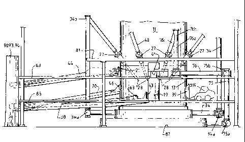
Figure 1 is a vertical cross-section through a
direct smelting vessel that forms part of one embodiment of
a direct smelting plant in accordance with the present
invention;
Figure 2 is a side elevation of the vessel and
the arrangement of platforms around the vessel and the
equipment on the platforms that form a major part of the
embodiment of the direct smelting plant;
Figure 2a is an enlarged side elevation of the
solids injection lance and hot ore supply lines indicated
by the arrow "A" in Figure 2;
Figure 3 is a side elevation of a lower part of
CA 02521705 2005-10-06
WO 2004/090173 PCT/AU2004/000472
12
the vessel and the arrangement of platforms around the
vessel and the equipment on the platforms that form a major
part of the embodiment of the direct smelting plant viewed
from a location that is 90 from the location from which
the vessel is viewed from in Figure 2;
Figure 4 illustrates the layout of the cast house
platform of the embodiment of the direct smelting plant;
Figure 5 illustrates the layout of the end tap
platform of the embodiment of the direct smelting plant;
Figure 6 is a computer-generated top plan view of
the embodiment of the direct smelting plant which
illustrates the cast house platform and equipment on that
platform and a section through the vessel at that height of
the vessel and equipment above that platform and with
equipment above that platform removed to clarify the view
of the plant; and
Figure 7 is a diagrammatic plan of the
arrangement of solids injection lances around the vessel
the supply lines for the lances.
DETAILED DESCRIPTION OF THE PREFERRED EMBODIMENT
The direct smelting plant shown in the Figures
includes a direct smelting vessel that is suitable
particularly for operation by the Hlsmelt process as
described in International patent application
PCT/AU96/00197. The following description is in the
context of smelting iron ore fines to produce molten iron
in accordance with the Hlsmelt process.
With reference initially to Figure 1, the
metallurgical vessel is denoted generally as 11 and has a
hearth that incudes a base 12 and sides 13 formed from
CA 02521705 2005-10-06
WO 2004/090173 PCT/AU2004/000472
13
refractory bricks, side walls 14 which form a generally
cylindrical barrel extending upwardly from the sides 13 of
the hearth and which include an upper barrel section and a
lower barrel section supporting water-cooled panels (not
shown), a roof 17 supporting water-cooled panels (not
shown), an outlet 18 for offgases, a forehearth 19 for
discharging molten metal continuously, and a tap-hole 21
for discharging molten slag during smelting.
In use of the vessel to smelt iron ore fines to
produce molten iron in accordance with the Hlsmelt process,
the vessel 11 contains amolten bath of iron and slag which
includes a layer 22 of molten metal and a layer 23 of
molten slag on the metal layer 22. The arrow marked by the
numeral 24 indicates the position of the nominal quiescent
surface of the metal layer 22 and the arrow marked by the
numeral 25 indicates the position of the nominal quiescent
surface of the slag layer 23. The term "quiescent surface"
is understood to mean the surface when there is no
injection of gas and solids into the vessel.
As can best be seen in Figures 2 and 3, the
vessel includes a series of platforms 79, 81, 83, 85 at
different heights of the vessel above ground level 87. The
platforms enable installation and operation of vessel and
other plant equipment described hereinafter around the
compact vessel 11 in a way which separates the various
operational functions of the equipment so as to minimise
interference between the various operations and,
accordingly, maximising operational safety. The heights of
the platforms 79, 81, 83, 85 are selected to enable workman
on the platforms to have convenient access to the plant
equipment. In addition, the "footprints" of the platforms
79, 81, 83, 85 are selected to permit overhead crane access
to selected areas of lower platforms and to provide
overhead protection for work areas of the lower platforms.
CA 02521705 2011-04-20
14
As is discussed in further detail hereinafter, the platforms 79, 81 are solids
injection lance platforms, the platform 83 is a cast house platform, and the
platform 85 is an
end tap platform.
As can best be seen in Figure 5, the vessel 11 includes 2 access doors 39 in
the
sides 13 of the hearth for allowing access to the interior of the vessel 11
for re-lining or other
maintenance work in the interior of the vessel. The access doors 39 are in the
form of steel
plates that are welded to the sides 13. When access to the interior of the
vessel is required, the
plates are cut away from the side walls and replacement plates are welded in
position after the
work in the vessel has been completed. As shown in Fig. 3 the access doors 39
are at the
same height as platform 85 at the lower end of the vessel 11. The access doors
39 are spaced
at least 90 apart around the circumference of the vessel. This spacing makes
it possible for
refractory wall demolition equipment to extend through the doors into the
vessel and
demolish a substantial part of the refractories of a refractory-lined side
wall while the vessel
is hot. The access doors 39 are sufficiently large to allow bob-cat 139 or
similar equipment
access to the interior of the vessel.
As can best be seen in Figure 1, the vessel 11 is fitted with a gas injection
lance 26 for delivering a hot air blast into an upper region of the vessel.
The lance 26 extends
downwardly through the roof 17 of the vessel 11 into the upper region of the
vessel. In use,
the lance 26 receives an oxygen-enriched hot air flow through a hot gas
delivery duct 31
(Figures 2 and 6) which extends from a hot gas supply station (not shown)
located some
distance away from the reduction vessel 11. The hot gas supply station
includes a series of hot
gas stoves (not shown) and an oxygen plant (not shown) to enable an oxygen
enriched air
stream to be passed through the hot gas stoves and into the hot gas delivery
duct 31 which
extends to a connection with
CA 02521705 2005-10-06
WO 2004/090173 PCT/AU2004/000472
the gas injection lance 26 at a location above the vessel
11. Alternatively oxygen may be added to the air stream
after the air stream has been heated by the stoves.
5 With reference to the Figures generally, the
vessel 11 is also fitted with 8 solids injection lances 27
extending downwardly and inwardly through openings (not
shown) in the side walls 14 of the vessel and into the slag
layer 23 for injecting iron ore fines, solid carbonaceous
10 material, and fluxes entrained in an oxygen-deficient
carrier gas into the metal layer 22.
The lance openings in the side walls 14 of the
vessel are located at the same height of the vessel 11 and
15 are spaced at equal distances around the circumference of
the vessel. The lances 27 are formed and are located in
the lance openings so that their outlet ends 28 are above
the surface of the metal layer 22 during operation of the
process. This position of the lances 27 reduces the risk
of damage through contact with molten metal and also makes
it possible to cool the lances by forced internal water
cooling without significant risk of water coming into
contact with the molten metal in the vessel.
The lances 27 are in 2 groups of 4 lances, with
the lances 27 in one group receiving hot iron ore fines
supplied via a hot ore injection system and the lances 27
in the other group receiving coal and flux via a
carbonaceous material/flux injection system during a
smelting operation. The lances 27 in the 2 groups are
arranged alternately around the circumference of the
vessel.
The hot ore injection system includes a pre-
heater (not shown) for heating the iron ore fines and a hot
ore transfer system that includes a series of supply lines
and a supply of carrier gas for transporting the hot ore
CA 02521705 2011-04-20
16
fines in the supply lines and injecting the hot ore fines at a temperature of
the order of 680 C
into the vessel. The general arrangement of the lances 27 and the supply lines
immediately
upstream of the lances 27 is shown diagrammatically in Figure 7.
With reference to the Figures generally, the hot ore injection system includes
a
main hot ore supply line 75 (Figures 2 to 5) and 2 branch lines 76 (Figures 2
to 4) that are
connected to diametrically opposed lances 27 and are arranged to supply hot
ore to these
lances 27 during a smelting operation. The hot ore injection system also
includes another
main hot ore supply line 33 (Figures 2 and 5) and 2 branch lines 34 (Figures 2
to 5) that are
connected to the other pair of diametrically opposed lances 27 and are
arranged to supply hot
ore to these lances 27.
As can be seen in Figures 2 to 5, the main supply line 75 runs on or close to
ground level from a remote location (not shown) away from the vessel and under
the end tap
platform 85 to a location 75a in Figures 2 and 3 and then vertically upwardly
from this
location through or adjacent the end tap platform 85 and the cast house
platform 83 to a
location 75b in Figures 2 to 4 above the cast house platform 83. The branch
lines 76 initially
extend horizontally in opposite directions from the main line 75 at the
location 75b and then
vertically upwardly at sections 76a (Figures 2 and 3) to locations 76b
(Figures 2 to 4) and
then inwardly and downwardly in short straight sections 76c to the inlets of
lances 27.
As can also be seen in Figures 2 and 3, the main supply line 33 runs on or
close to ground level from a remote location (not shown) away from the vessel
to a location
33a in Figure 5 and the line branches into the branch lines 34 at this
location. These branch
lines define a V-shape. The branch lines 34 extend on or close
CA 02521705 2005-10-06
WO 2004/090173 PCT/AU2004/000472
17
to ground level under the end tap platform 85 to locations
34a (Figures 2 and 3) and then vertically upwardly from
these locations through or adjacent the end tap platform 85
and the cast house platform 83 to the locations 34b (Figure
2) and then inwardly and downwardly in short straight
sections 34c (Figure 2, only one shown) to the inlets of
lances 27.
The above-described arrangement of the pairs of
main and branch lines avoids interference between the lines
in the confined space around the vessel.
The carbonaceous material/flux injection system
includes similar main supply lines 39, 91 and branch supply
lines 40, 92, respectively for diametrically opposed pairs
of the lances 27.
The lances 27 are arranged to be removable from
the vessel 11.
The offgas outlet 18 of the vessel 11 is
connected to an offgas duct 32 (shown in Figures 2, 6 and
7) which transports the offgas away from the vessel 11 to a
treatment station (not shown) where it is cleaned and
passed through heat exchangers for preheating the materials
fed to the vessel 11. The Hlsmelt process preferably
operates with air or oxygen-enriched air and therefore
generates substantial volumes of offgas and requires a
relatively large diameter offgas duct 32. As can best be
seen in Figure 2, the offgas duct includes a gently
inclined first section 32a extending from the offgas outlet
18 of the vessel 11 and a vertically extending second
section 32b that extends from the first section 32a.
The hot gas delivery duct 31 and the offgas duct
32 extend away from the upper part of the vessel 11 to
remote locations (not shown) and therefore occupy space in
CA 02521705 2005-10-06
WO 2004/090173 PCT/AU2004/000472
18
that region of the vessel and therefore have an impact on
the positioning of plant equipment such as overhead cranes
or other mobile handling equipment that is required for
maintenance of the vessel and a cooling water circuit for
the water-cooled panels in the side walls 14 and the roof
17 of the vessel 11.
As is indicated above, the side walls 14 and the
roof 17 of the vessel 11 support water-cooled panels (not
shown) and the plant includes a cooling water circuit. The
cooling water circuit supplies water to and removes heated
water from the water-cooled panels and thereafter extracts
heat from the heated water before returning the water to
the water-cooled panels.
In a smelting operation in accordance with the
Hlsmelt process, ore fines and a suitable carrier gas and
coal and a suitable carrier gas are injected into the
molten bath through the lances 27. The momentum of the
solid materials and the carrier gases causes the solid
materials to penetrate the metal layer 15. The coal is
devolatilised and thereby produces gas in the metal layer
15. Carbon partially dissolves in the metal and partially
remains as solid carbon. The ore fines are smelted to
metal and the smelting reaction generates carbon monoxide.
The gases transported into the metal layer and generated by
devolatilisation and smelting reactions produce significant
buoyancy uplift of molten metal, solid carbon and slag
(drawn into the metal layer as a consequence of
solid/gas/injection) from the metal layer 15 which
generates upward movement of splashes, droplets and streams
of molten metal and slag, and these splashes, droplets and
streams entrain slag as they move through the slag layer.
The buoyancy uplift of molten metal, solid carbon and slag
causes substantial agitation of the slag layer 16, with the
result that the slag layer expands in volume. In addition,
the upward movement of splashes, droplets and streams of
CA 02521705 2011-04-20
19
molten metal and slag - caused by buoyancy uplift of molten metal, solid
carbon and slag -
extend into the space above the molten bath and forms a transition zone.
Injection of the
oxygen-containing gas via the lance 26 post-combusts reaction gases, such as
carbon
monoxide and hydrogen, in the upper part of the vessel. Offgases resulting
from the post-
combustion of reaction gases in the vessel are taken away from the upper part
of the vessel
through the offgas duct 32.
Hot metal produced during a smelting operation is discharged from the vessel
11 through a metal tapping system that includes the forehearth 19 and a hot
metal launder 40
connected to the forehearth. The outlet end of the hot metal launder 41 is
positioned above a
hot metal ladle station (not shown) so as to supply molten metal downwardly to
ladles located
at the station.
The plant includes an end metal tapping system for tapping molten metal from
the vessel I1 at the end of a smelting operation out of the lower part of the
vessel and
transporting that molten metal away from the vessel 11. The end metal tapping
system
includes a metal end tap hole 63 in the vessel and a launder 38 for
transferring molten metal
discharged from the vessel 11 via the tap hole to a containment metal pit 90
at ground level.
Ideally this pit 90 is covered (not shown) from the elements to prevent direct
contact between
hot metal in the pit and water. The end metal tapping system also includes a
metal tap hole 43
in the forehearth 19 and a launder 40 for transferring molten metal discharged
from the
forehearth 19 via the tap hole to the main hot metal launder 38. An end tap
drill 59 is also
provided to open the tap holes 63, 43 to release metal from the vessel and the
forehearth.
The plant includes a slag tapping system for tapping molten slag from the
vessel 11 periodically from
CA 02521705 2011-04-20
the lower part of the vessel and transporting that slag away from the vessel
11 during a
smelting operation. The slag tapping system includes a slag notch 21 in the
vessel 11 and a
launder 44 with 2 end branches 80, 82 for transferring molten slag discharged
from the vessel
11 via the slag notch 21 downwardly from the height of the cast house platform
83 into
separate slag containment pits 93, 94 at ground level 87. Two pits are
provided so that one pit
can be out of service and allowed to cool down prior to the slag being removed
while the
other pit is in service and receiving molten slag. A slag notch plug and
pricker machine 61 is
provided to open and seal the slag notch 21 to release slag from the vessel
11.
The plant includes a slag tapping system for draining slag from the vessel 11
at
the end of a smelting operation. The slag end tapping system includes a slag
tap hole 46 in the
vessel 11 and a main launder 70 and a branch launder 72 for transferring
molten material
discharged from the vessel 11 via the slag tap hole 46 to the containment pit
93. A branch
launder 95 connects the slag launder 70 to the hot metal launder 38. The
branch launder 95 is
used to transfer molten metal that usually flows from the vessel when the tap
hole 46 is first
opened to the metal containment pit 90. Prior to an end tap, the branch
launder 72 is blocked
so that molten material can only flow to the metal containment pit 91 via the
branch launder
95. Towards the end of the metal flow, the branch launder 95 is blocked and
the branch
launder 72 is unblocked so that flow of molten material is diverted to the
slag pit 93. A slag
drain drill 68 is provided for opening the tap hole 46 to release slag from
the vessel. A mud
gun 66 is provided to close an open tap hole 46.
As is indicated above, the vessel includes a series of platforms 79, 81, 83,
85
at different heights of the vessel above ground level 87. The platforms enable
CA 02521705 2005-10-06
WO 2004/090173 PCT/AU2004/000472
21
installation and operation of vessel and other plant
equipment.
The lowest platform, the and tap platform 85, is
positioned in relation to the vessel 11 at a height that is
selected so that workman on the platform can have
convenient access to the and metal tapping system (metal
and tap hole 63, launder 38, metal tap hole 43, launder 40,
and end tap drill 59), the slag and tapping system (slag
tap hole 46, launder 70, branch launder 95, slag drain
drill 68, mud gun 66), and the access doors 39. Equipment
such as the metal end tap drill, slag drain drill 68, and
mud gun 66 are mounted directly on the platform. The
platform also includes 2 overhead crane access areas 55
that are essentially clear spaces on and from which
equipment and materials can be lifted, for example to
facilitate re-lining the interior of the vessel 11.
The next highest platform, the cast house
platform 83, is positioned in relation to the vessel 11 at
a height that is selected so that workman on the platform
can have convenient access to the metal tapping system
(forehearth 19 and hot metal launder 41) and the slag
tapping system (slag notch 21, launder 44, and slag notch
plug and pricker machine 61). The footprint of the
platform 83 is selectively formed so that the platform does
not extend into the space above the overhead access areas
55 of the end tap platform 85 so that there is clear
overhead crane access to these areas 55. The footprint of
the platform 83 is also selectively formed so that the
platform extends above the work areas in the immediate
vicinity of the end metal and slag tapping systems and the
access doors 39 on the end tap platform 85 to provide
overhead protection for workman in these areas.
The next highest platforms, the lance platforms
79, 81, are positioned in relation to the vessel 11 at
CA 02521705 2005-10-06
WO 2004/090173 PCT/AU2004/000472
22
heights that are selected so that workman on the platforms
can have convenient access to the lances 27.
The footprint of the platform 81 is shown in
Figure 3. The footprint of the platform 81 is selectively
formed so that the platform does not extend into the space
above the overhead access areas 55 of the end tap platform
85 so that there is clear overhead crane access to these
areas 55. The footprint is also selectively formed so that
the platform extends above the work areas in the immediate
vicinity of the metal and slag tapping systems to provide
overhead protection for workman working in these areas.
In addition to the above-described plant
equipment being arranged on a series of platforms 79, 81,
83, 85, the equipment is also arranged on the platforms
within a series of circumferentially and vertically
extending zones that further enable installation and
operation of all the above-described equipment around the
compact vessel 11 in a way which separates the various
operational functions of the equipment so as to minimise
interference between the various operations and,
accordingly, maximising operational safety.
Specifically, the layout of the installation is
divided into the following 3 functional zones that extend
vertically and are spaced circumferentially around the
vessel 11 and radiate outwardly of the central upright axis
of the vessel.
Zone 1: General Access and Services
This zone, which extends approximately 180 around the
circumference of the vessel 11 contains:-
The footprints of the overhead hot gas delivery
duct 31 and the offgas duct 32.
CA 02521705 2011-04-20
23
= The access doors 39 in the vessel 11.
Zone 2 : Metal Tapping
This zone contains:-
The metal tapping system (forehearth 19 and hot metal launder 40).
= The end metal tapping system (metal end tap hole 63, launder 38, metal
tap hole 43, launder 40, and end tap drill).
Zone 3: Slag Tapping
This zone contains:-
The slag tapping system (slag notch 21, launder 44, and slag notch plug
and pricker machine 61).
= The slag end tapping system (slag tap hole 46, launder 70, branch
launder 95, slag drain drill 68, and mud gun 66).
The plant also includes the zones, ie the space, above the above-described
overhead crane access areas 55 that enable materials and equipment to be
lifted onto and
removed from the end tap platform. The overhead access is particularly
important for efficient
lifting of materials and equipment required for re-lining or other maintenance
work on the
interior of the vessel.
Many modifications may be made to the embodiment of the present invention
described above without departing from the spirit and scope of the invention.