Note: Descriptions are shown in the official language in which they were submitted.
CA 02521796 2005-09-30
SYSTEM AND TRACKER FOR TRACKING AN OBJECT, AND RELATED METHODS
BACKGROUND OF THE INVENTION
1. Field Of The Invention
[0001] The present invention relates to tracking apparatus. More specifically,
the present
invention relates to a system, a tracker, and related methods for tracking
spatial position and
orientation of an object.
2. Descriution of the Related Art
[0002] It is often desired to track the position and orientation of an object.
For example, in
the electronics industry it is often necessary to match surfaces or insert
parts in predetermined
positions. This is especially significant where a robot or robotic arm is
used. In the medical
field, it is often necessary to track the position of a medical instrument in
order to determine the
location of an object within a body. For example, knowledge of the position of
a surgical tool
during neurosurgery or location of a target such as a tumor while radiation
therapy treatment is
occurring, have always been critical issues.
[0003] Also, in the medical field, recent diagnostic advances such as
computerized
tomographic (CT) scans, magnetic resonance imaging (MRI) scanning, and
positron emission
tomographic (PET) scanning have greatly facilitated preoperative diagnosis and
surgical or
radiation planning. Precision and accuracy of the scanning technologies,
however, have not been
fully developed in order to utilize such diagnostic advances during treatment
to their fullest
potential. For example, with respect to radiation therapy, it is assumed that
the patient's position
and the target's position within the patient will be grossly, or nominally,
the same at the time of
radiation treatment, as it was at the time the radiation treatment plan was
created. If the position
of the target is not the same as it was at the time the treatment plan was
determined, the dose of
radiation may not be delivered to the correct location within the patient's
body. Because patients
are not always positioned properly on the treatment table of the radiation
therapy device, which
may be a linear accelerator or a cobalt unit, and because organs of a patient
may move within the
patient from day to day, the target may not be positioned at the exact
location where the radiation
-2-
CA 02521796 2005-09-30
therapy plan has assumed it would be located. Various systems and tools have
been developed
to determine the target position and orientation.
[0004] The position of an object or tool is typically defined by three
translation parameters
(x, y, z) and three rotation parameters (pitch, roll, yaw ) corresponding to
six degrees of freedom.
The translation parameters (x, y, z) indicate three-dimensional position, e.g.
forward and back (y-
axis), left and right (x-axis), up and down (z-axis), and three rotation
parameters (pitch, roll,
yaw) indicate orientation of the tool or object, e.g. rotation about the x-
axis (pitch), rotation
about the y-axis (roll), and rotation about to the z-axis (yaw). Various
systems are available for
determining the spatial position and orientation of an object. One such system
includes use of a
mechanical arm to track the location of a medical tool or probe which can be
used to further
determine the location of a target. In order to locate the target, the tool or
probe can be affixed to
the mechanical arm having a known reference position. A computer system tracks
the tool or
probe while an operator repositions the tool or probe along with the
mechanical arm. The
geometry of the mechanical arm is known such that movement of the tool or
probe in
conjunction with the mechanical arm provides the computer system continuous
position
information regarding the tool or probe. In an invasive procedure, the tool or
probe can have a
fixed length. Thus, contacting the target with the end of the tool can provide
a position location
of the target. In a noninvasive procedure, a probe, such as an ultrasound
device, can be used to
locate both the position and the orientation of the target. Recognized,
however, is that the
mechanical arm can be cumbersome or difficult for the operator to work with.
Additionally, the
mechanical arm can be subject to inaccuracies caused by component
imperfections due to
manufacturing tolerances and mechanical wear and by the effects of gravity on
the arm, which to
varying degrees depending upon the arm orientation, can act to offset the arm
position from that
calculated.
[0005] Another such system can include either sonic, optical, radio frequency,
or even
magnetic detectors affixed to the tool or object and active radiating emitters
and a computer
system or unit. In order to determine the six degrees of freedom of the object
or tool, generally,
at least three points on the object must be detected. Recognized, however, is
that the circuitry
involved can be cumbersome or can require modification to the tool or object.
For example,
generally, wiring from the detectors used to transfer the received signal to a
decoder and to the
computer system or unit must be affixed on or adjacent to the tool or object.
Often, such wiring
-3-
CA 02521796 2005-09-30
provides an obstacle to the operator. Also, most detectors typically function
by detecting the
time, frequency, or amplitude differential between the various detectors in
receiving usually at
least a pair of external source signals from the emitters in order to
determine the spatial position
of the tool or object. Thus, the emitter or detector circuitry must, by its
nature, be complicated in
order to provide for the ability to separately activate each detector.
[0006] A similar system can instead include either sonic, optical, or radio
frequency emitters
affixed to the tool or object and receivers such as sonic, optical, or radio
frequency sensors, and a
computer system or unit. As described with respect to the use of detectors, in
order to determine
the six degrees of freedom of the object or tool, at least three points on the
object typically must
generally be detected. The emitters can be either active or passive. Active
emitters, however,
are subject to the same wiring interference as that of detectors. Wiring
generally supplies
encoded signals to each of the emitters which function as markers and which
are either activated
in sequence or provide sonic, optical, or radio frequency signals on different
frequencies. Thus,
the emitter or external detector circuitry must therefore, by their nature, be
complicated in order
to provide for the ability to separately activate each emitter. To reduce the
complication and the
emitter or external detector circuitry, the emitters can instead fiznction
simultaneously emitting
the same type of signal. Where the emitters produce such same type signal,
however, the
emitters are subject to co-emitter interference when the emitters overlap each
other with respect
to the field of view of the sensors.
(0007] Unlike active emitters, passive emitters are generally in the form of a
reflector and do
not necessarily suffer the same wiring limitations. Passive emitters are
becoming the preferred
type of emitter as they can be installed on virtually any type of object or
tool to provide a relative
location of the object or tool or a portion, thereof. Passive emitters supply
their signal via active
radiating external emitters positioned within view of the passive emitters.
The signal from the
active emitters is reflected by the passive emitters. The circuitry involved
with passive emitters
is generally less complicated as they tend to function simultaneously, each
emitting or reflecting
the same type of signal. Passive emitters, however, are correspondingly also
subject to co-
emitter interference when the emitters overlap each other with respect to the
field of view of the
sensors.
-4-
CA 02521796 2005-09-30
[0008] Both active and passive emission techniques operate by projecting a
geometric
representation or extension of the object or tool formed by the emitters onto
the field of view of a
pair of spaced sensors. Various implementations of sensors have been used, the
most popular
being the use of two cameras positioned spaced apart a known distance and
angled in the general
direction of the object or tool such that the three-dimensional position of
the object or tool can be
obtained by triangulation from the positions of the emitters. For example, a
camera or opti-
electrical motion measurement system, known as the Polaris~, by Northern
Digital Inc., Ontario
Canada, has been used for triangulating the position of optically trackable
tools.
[0009] Specifically, a computer system, using mathematical processing, can
determine the
three dimensional coordinates of each one of the emitters associated with the
object or tool. The
position of each of the emitters can be used to determine the position of the
object or tool relative
to a three dimensional coordinate system centered at a preselected point in
space, typically at a
point fixed relative to the sensors. The positional relationship to each other
of each of the
emitters associated with the object or tool can be utilized to fiuther
determine the orientation in
space of the object or tool. Generally, at least three of the emitters must be
detected and must be
unobscured by any adjacent emitters. Additionally, the sensors generally
require the emitters to
be a minimum distance, for example, 3-5 cm apart. Theoretically, such systems
should provide
three unobstructed emitters for most of a sphere created by the six degrees of
freedom. One of
the more modern types of passive emission system utilizes passive retro-
reflectors which can be
affixed to the object or tool and which reflect directly back to a pair of
active emitter arrays
adjacent a pair of optical sensors. This type of system allows the optical
sensors to be positioned
relatively close together.
[00010] Recognized by the Applicant is that the active systems using a single
frequency,
wavelength, and amplitude, and the passive systems which inherently do so, are
subject to
significant field of view limitations. For example, where the three or more
emitters are
positioned on the tool or object, the emitters will tend to line-up or occlude
each other for a large
segment of the sphere created by the six degrees of freedom. Where emitter
interference occurs,
all emitters involved are generally deemed by the computer to be unreliable or
unusable. If one
or more of those emitters are required by the computer to determine the
position of the tool, the
tracking of the tool will be lost until three unobstructed emitters are
reacquired in the field of
view of the sensors. Though in some instances, the prior art has tried to
"wallpaper" the tool or
-5-
CA 02521796 2005-09-30
an object with upwards of 24 emitters in order to have at least three
unobscured emitters, still
elusive has been a system, tracker, or related methods for providing at least
three unobscured
emitters throughout substantially the entire sphere created by the six degrees
of freedom.
[00011] Also recognized by the Applicant is that mounting the emitters
directly to a tool or
object frequently exacerbates any existing obstruction problems. For example,
if the emitters are
mounted directly on the handle of a tool, the operator will have to try to
work around the emitters
so as not to cover or otherwise obscure them. Additionally recognized by the
Applicant is that
the point of interest on a tool or object can be directly determined by the
orientation of the
emitters. Thus, any mount positioned on the tool or object to carry the
emitters must be precisely
positioned in the correct juxaposition in order to prevent calculation errors.
Such mount should
also be capable of being easily and quickly disconnected and accurately and
repeatably
reconnected. For a tool, such as an ultrasound device, which may be frequently
separated from
the mount in order to clean, service, or inspect the device, it may be
imperative to productivity to
have such a connection.
-6-
CA 02521796 2005-09-30
SUMMARY OF THE INVENTION
[00012] In view of the foregoing, embodiments of the present invention
advantageously
provide a system, tracker, and methods related to use of a tracker that
provides a user the ability
to track both the three-dimensional position and the orientation of a movable
object over
substantially all possible object orientations without significant occlusion.
Advantageously,
embodiments of the present invention also provide a tracker that is size
scalable in order to meet
requirements of the movable object and to control the accuracy of the tracking
solution.
Advantageously, embodiments of the present invention also provide a geometric
indicator or
emitter design which forms a plurality of preferably dissimilar geometric
figures composed of
three or more indicators or emitters preferably in the form of retro-
reflective spheres that are
readily distinguishable by an optical detector or camera system.
Advantageously, embodiments
of the present invention also provide flanges and other "obfuscating"
structures that occlude or
prevent coincident alignment of specific optical indicators from view by the
optical detector or
camera system. This prevents indicators which comprise one geometric figure
from becoming
juxtaposed or optically coincident with indicators which form another
geometric figure, which
would result in the indicators being unusable to the optical detector or
camera system, and thus
loss of a tracking solution. Advantageously, embodiments of the present
invention incorporate a
mechanical quick disconnect to allow ready removal from the movable object
being tracked
while still providing positioning functionality and which compels the tracker
into the correct
mounting position on the movable object, to prevent use of the tracker in an
incorrect state.
[00013] Embodiments of the present invention provide a system for tracking a
three-
dimensional position and an orientation of a movable object. The system
generally includes a
tracker having an optically trackable body adapted to connect to the movable
object. A plurality
of optical indicators are connected or mounted to the optically trackable body
to form a plurality
of preferably dissimilar geometric figures. Separating means, such as, for
example, a plurality of
obfuscating flanges is provided, to optically separate each of the plurality
of optical indicators
from each other to prevent each of the plurality of indicators from becoming
optically coincident
with another one of the plurality of indicators when viewed along a collinear
viewing path
extending directly through either pair of the plurality of indicators. The
system also includes an
apparatus to track a trackable body having an optical detector to
simultaneously detect the three-
dimensional position of at least three of the plurality of optical indicators,
and a determiner to
CA 02521796 2005-09-30
determine the three-dimensional position and orientation of the optically
trackable body from the
position of the optical indicators, and thus, the three-dimensional position
and orientation of the
movable object.
[00014] More specifically, in an embodiment of the present invention the
system includes a
tracker having a plurality of separate and spaced apart optical indicators,
advantageously in the
form of optical retro-reflective spheres mounted or connected to an optically
trackable body.
The plurality of indicators are adapted to be optically tracked over a subset
of possible movable
object orientations. The plurality of indicators have a preferably dissimilar
preselected segment
length between each pair combination, whereby a plurality of combinations of
at least three of
the plurality of indicators define a plurality of geometric figures. The three-
dimensional location
of the indicators and the orientation of the geometric figures provide three-
dimensional
positional data and orientation data of the movable object.
[00015] The optically trackable body having the plurality of indicators
mounted thereto
includes a proximal body end portion, a distal body end portion, a medial body
portion
connected to and extending between the proximal body end portion and the
distal body end
portion, and a longitudinal axis. The optically trackable body also includes
separating means for
optically separating each of the plurality of indicators from each other to
prevent each of the
plurality of indicators from becoming optically coincident with another one of
the plurality of
indicators when viewed along a plurality of preselected viewing paths
extending directly through
each pair combination of the plurality of indicators to thereby enhance
optical detection of the
plurality of indicators to thereby determine the positional location and
orientation of the
movable object.
[00016] In an embodiment of the present invention, the separating means
includes a plurality
of obfuscators provided, e.g., by a plurality of obfuscating flanges. The
plurality of obfuscating
flanges can include a plurality of longitudinal medial body portion
obfuscating flanges sized and
positioned substantially parallel to and spaced apart from the longitudinal
axis of the medial
body portion of the optically trackable body. The plurality of medial body
portion obfuscating
flanges optically separate each indicator of the plurality of indicators
mounted to the medial body
portion of the optically trackable body from each adjacent indicator of the
plurality of indicators
also mounted to the medial body portion of the optically trackable body. This
prevents or
_g_
CA 02521796 2005-09-30
significantly reduces a possibility of each indicator of the plurality of
indicators, mounted to the
medial body portion of the optically trackable body, becoming optically
coincident with each
respective adjacent indicator of the plurality of indicators, also mounted to
the medial body
portion of the optically trackable body, when viewed along either of the
plurality of preselected
viewing paths extending directly through each respective pair of the plurality
of indicators
mounted to the medial body portion of the optically trackable body.
[00017] The plurality of obfuscating flanges can also include a radial medial
body portion
obfuscating flange positioned substantially axially parallel with the
longitudinal axis of the
medial body portion of the optically trackable body. The radial medial body
portion obfuscating
flange is positioned and sized to optically separate each indicator of the
plurality of indicators
mounted to the distal body end portion of the optically trackable body from
each indicator of the
plurality of indicators connected or mounted to the medial body portion of the
optically trackable
body. This prevents, or significantly reduces a possibility, each indicator of
the plurality of
indicators connected or mounted to the distal body portion of the optically
trackable body from
becoming optically coincident with either indicator of the plurality of
indicators connected or
mounted to the medial body portion of the optically trackable body, when
viewed along either of
the plurality of preselected viewing paths extending directly through each
indicator of the
plurality of indicators connected or mounted to the distal body portion of the
optically trackable
body and either indicator of the plurality of indicators connected or mounted
to the medial body
portion of the optically trackable body.
[00018] The distal body end portion of the optically trackable body, for
example, can have a
pair of adjacent indicators connected or mounted thereto. In such
configuration, the plurality of
obfuscating flanges can include a distal body end portion obfuscating flange
positioned
substantially axially perpendicular to the longitudinal axis of the medial
body portion of the
optically trackable body. The distal body end portion obfuscating flange is
positioned and sized
to optically separate a first indicator of the pair of indicators connected or
mounted to the distal
body end portion of the optically trackable body from a second indicator of
the pair of indicators
connected or mounted to the distal body portion of the optically trackable
body. This can
prevent the first indicator of the pair of adjacent indicators connected or
mounted to the distal
body end portion of the optically trackable body from becoming optically
coincident with the
second indicator of the pair of indicators connected or mounted to the distal
body end portion of
-9-
CA 02521796 2005-09-30
the optically trackable body, when viewed along either of the plurality of
preselected viewing
paths extending directly through the first and second indicators of the pair
of adjacent indicators
connected or mounted to the distal body end portion of the optically trackable
body.
[00019] The optically trackable body can also include an interior mount recess
inwardly
extending from the proximal body end portion into the medial body portion. The
interior mount
recess is adapted to slidably receive at least portions of a mounting
connector adapted to connect
the optically trackable body to the movable object. The medial body portion of
the optically
trackable body can further include a mounting connector retention recess
extending between
outer surface portions of the medial body portion and inner surface portions
of the interior mount
recess and positioned substantially normal to the interior mount recess to
house at least portions
of a mounting connector retention member provided to fixedly retain the
mounting connector
within the interior mount recess, when so positioned. Advantageously, this can
form a quick
disconnect.
[00020] The proximal body end portion of the optically trackable body can
further include a
proximal body end mounting extension connected to and integral with the
proximal body end
portion of the body. The proximal body end mounting extension can extend
substantially
perpendicular to and outwardly from the longitudinal axis of the optically
trackable body. The
proximal body end mounting extension can have a substantially flat planer
proximal surface
adapted to interface with a corresponding planer surface of either the movable
object or a
movable object mounting interface of an intermediate mount. Advantageously,
this allows for
ease of positioning or mounting the optically trackable body to the movable
object.
[00021] The system also includes an apparatus to track a trackable body or
camera subsystem
including an optical detector and a determiner. The optical detector has an
optical detector body
positioned separate and spaced apart from the optically trackable body at a
predetermined three-
dimensional sensor reference location. The optical detector preferably
includes a pair of separate
and spaced apart optical receivers connected to the optical detector body,
each having a field of
view and being adapted to receive optical energy emitted or reflected by each
of the plurality of
optical indicators when positioned in the field of view. The optical receivers
can detect the
three-dimensional sphere position of each of the plurality of indicators when
positioned
simultaneously within the field of view of both of the optical receivers to
produce a plurality of
-10-
CA 02521796 2005-09-30
position signals representing such three-dimensional indicator positions. When
the plurality of
indicators are in the form of optical retro-reflective spheres, the optical
detector can include a
pair of infrared illuminators. A first illuminator is positioned adjacent to
one of the pair of
separate and spaced apart optical receivers and a second illuminator is
positioned adjacent to the
other of the pair of separate and spaced apart optical receivers to
selectively illuminate each of
the plurality of optical retro-reflective spheres when positioned in the field
of view of the
respective adjacent optical receiver. This provides the requisite optical
energy necessary to view
the optical retro-reflective spheres within the field of view of the
respective adjacent optical
receiver.
[00022] The determiner is in communication with the optical detector and is
responsive to the
plurality of position signals produced by the optical detector to determine
the three-dimensional
indicator position of each of the plurality of indicators when positioned
simultaneously within
the field of view of both of the optical receivers of the optical detector.
The determiner has a
memory associated therewith to store a table of definitions containing unique
segment lengths
between each pair of the plurality of optical indicators. Responsive to the
segment lengths, the
determiner can determine which of the plurality of geometric figures is in
view of the optical
receivers. Once the particular geometric figure is identified, by determining
the orientation of
the particular geometric figure, the determiner can then further determine the
three-dimensional
position and the orientation of the tracker, and thus, the movable object.
[00023] Advantageously, also provided are methods for tracking a position and
an orientation
of a movable object. For example, in an embodiment of the present invention, a
method for
tracking a position and an orientation of a movable object includes connecting
a plurality of
indicators to an optically trackable body to form a plurality of geometric
figures and connecting
the optically trackable body to the movable object. The optically trackable
body includes at least
one obfuscating flange sized and positioned to optically separate, at a
minimum, a first of the
plurality of indicators from a second of the plurality of indicators when
viewed along a
preselected viewing path. An optical detector can be used to view one of the
plurality of
geometric figures when positioned in its field of view. A determiner can then
be used to identify
which one of the plurality of geometric figures is positioned in a field of
view of the optical
detector. Analysis of the position and orientation of the identified geometric
figure in the field of
-11-
CA 02521796 2005-09-30
view of the optical detector can then be used to determine the position and
orientation of the
movable object.
[00024] By continuously analyzing the position and orientation of the
geometric figures, the
position and orientation of the movable object can be continuously re-
determined while the
geometric figures remains in the field of view of the optical detector. The
position and
orientation of the movable object can be continuously tracked through various
rotations of the
movable object by obfuscating a first of the plurality of indicators as it
leaves the field of view of
the optical detector to prevent the first of the plurality of indicators from
becoming optically
coincident with a second of the plurality of indicators. This allows the
optical detector to thereby
replace the one of the plurality of geometric figures positioned in the field
of view of the optical
detector with another one of the plurality of geometric figures positioned in
the field of view of
the optical detector. This second of the plurality of figures can then be
tracked until replaced
with a third of the plurality of figures.
[00025] Also for example, in an embodiment of the present invention, a method
for tracking a
position and an orientation of a movable object includes connecting an
optically trackable body
having a plurality of indicators to the movable object, the optically
trackable body having a first
obfuscating flange sized and positioned to optically separate a first of the
plurality of indicators
from a second of the plurality of indicators and a second obfuscating flange
sized and positioned
to optically separate the second of the plurality of indicators from a third
of the plurality of
indicators. During movement of the movable object, and thus the trackable
body, the first
obfuscating flange is positioned to obfuscate the first of the plurality of
indicators to prevent the
first of the plurality of indicators from becoming optically coincident with
the second of the
plurality of indicators. An optical detector which can simultaneously detect
the position of
multiple indicators is positioned to view a subset of the plurality of
indicators in a field of view
of the optical detector to identify which of the plurality of indicators are
positioned in a field of
view of the optical detector. Having detected and identified the plurality of
indicators, the
position of at least three of the plurality of indicators in the field of view
of the optical detector
can then be analyzed to determine the position and orientation of the movable
object, allowing
tracking of the move object.
-12-
CA 02521796 2005-09-30
[00026] Advantageously, also provided are methods for enhancing detection of a
trackable
body. For example, in an embodiment of the present invention, a method for
enhancing
detection of a trackable body includes positioning at least one obfuscating
flange on a trackable
body having a plurality of optical indicators to optically separate a first of
the plurality of optical
indicators from a second of the plurality of optical indicators. The
positioning of the at least one
obfuscating flange allows for inhibiting the first of the plurality of optical
indicators from
becoming optically coincident with the second of the plurality of optical
indicators when viewing
the trackable body along a preselected viewing path by obfuscating the first
of the plurality of
optical indicators from the second of the plurality of optical detectors with
the at least one
obfuscating flange.
[00027] Advantageously, embodiments of the present invention include a tracker
having a
compact lightweight design, that is easy to install to a movable object,
inexpensive to
manufacture, and is relatively simple to use. Advantageously, the tracker can
be easily removed
or interchanged with other movable objects enabling a variety of different
applications.
Advantageously, the tracker has an intelligent juxtaposition of optical
indicators and obfuscators
that allow optical tracking of the tracker, with few exceptions, at
substantially any given
orientation of the tracker. The optical detector or camera system is provided
enough optical
indicators to identify and locate the tracker without those indicators
interfering with each other.
Advantageously, the size, shape, and juxtaposition of the indicators and the
obfuscating flanges
of the tracker allow for utilization of nearly the full potential of various
optical detector or
cameras systems having a hemispherical or spherical field of view.
Advantageously, a single
tracker can be used with movable objects of various size and shape.
Advantageously, the tracker
is scalable in that the longitudinal length and/or lateral width of the
optically trackable body can
be increased thus, the size of the lengths between optical indicators can be
increased which
improves tracking solution accuracy. Advantageously a position determiner can
be provided a
trackable body tag, such as a serial number, preferably assigned to the
tracker at the time of
manufacture, to allow automated calibration of the tracker with a specifically
identified movable
object mount and/or the movable object. Advantageously, regarding medical
implementation of
the tracker, the optically trackable body includes such versatility such that
it can be connected to
a treatment table of a radiation therapy treatment machine to allow a user to
align a patient for
radiation delivery. Additionally, at the time of manufacture, the movable
object mount can be
-13-
CA 02521796 2005-09-30
fitted to the movable object, such as an ultrasound probe, and calibrated to
the movable object
mount to further maximize precision of the mounting.
-14-
CA 02521796 2005-09-30
BRIEF DESCRIPTION OF THE DRAWINGS
[00028] So that the manner in which the features and advantages of the
invention, as well as
others which will become apparent, may be understood in more detail, a more
particular
description of the invention briefly summarized above may be had by reference
to the
embodiments thereof which are illustrated in the appended drawings, which form
a part of this
specification. It is to be noted, however, that the drawings illustrate only
various embodiments
of the invention and are therefore not to be considered limiting of the
invention's scope as it may
include other ei~ective embodiments as well.
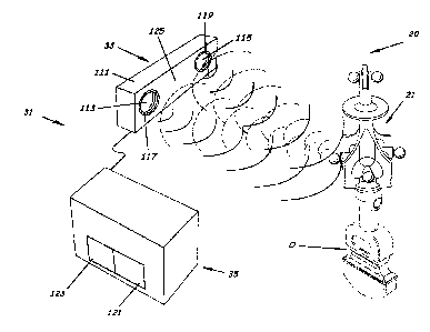
[00029] FIG. 1 is a system for tracking position and orientation of a movable
object,
according to an embodiment of the present invention;
[00030] FIG. 2 is an exploded perspective view of a portion of a system for
tracking position
and orientation of a movable object according to an embodiment of the present
invention;
[00031] FIG. 3 is an exploded perspective view of a portion of a system for
tracking position
and orientation of a movable object according to an embodiment of the present
invention;
(00032] FIG. 4 is perspective view of an optically trackable body for tracking
position and
orientation of a movable object according to an embodiment of the present
invention;
[00033] FIG. 5 is a perspective view of a portion of a system for tracking
position and
orientation of a movable object according to an embodiment of the present
invention;
[00034] FIG. 6 is a sectional view of a tracker for tracking position and
orientation of a
movable object taken along the 6-6 line of FIG. 5 according to an embodiment
of the present
invention;
[00035] FIG. 7 is a perspective view of an optically trackable body for
tracking position and
orientation of a movable object taken along the 7-7 line of FIG. 4 according
to an embodiment of
the present invention;
[00036] FIG. 8 is a perspective view of an optically trackable body for
tracking position and
orientation of the movable object taken along the 8-8 line of FIG. 4 according
to an embodiment
of the present invention;
-15-
CA 02521796 2005-09-30
[00037] FIG. 9 is a perspective view of an optically trackable body for
tracking position and
orientation of the movable object taken along the 9-9 line of FIG. 4 according
to an embodiment
of the present invention;
[00038] FIG. 10 is a perspective view of an optically trackable body for
tracking position and
orientation of the movable object taken along the 10-10 line of FIG. 9
according to an
embodiment of the present invention;
[00039] FIG. 11 is a perspective view of an optically trackable body for
tracking position and
orientation of the movable object taken along the 11-11 line of FIG. 10
according to an
embodiment of the present invention;
[00040] FIG. 12 is a perspective view of an optically trackable body for
tracking position and
orientation of the movable object taken along the 12-12 line of FIG. 11
according to an
embodiment of the present invention;
[00041] FIG. 13 is a fragmentary and exploded view of a tracker for tracking
position and
orientation of a movable object having portions thereof broken away for
clarity according to an
embodiment of the present invention; and
[00042] FIG. 14 is flowchart of a method for tracking position and orientation
of a movable
object according to an embodiment of the present invention.
-16-
CA 02521796 2005-09-30
DETAILED DESCRIPTION
[00043] The present invention will now be described more fully hereinafter
with reference to
the accompanying drawings, which illustrate embodiments of the invention. This
invention may,
however, be embodied in many dii~erent forms and should not be construed as
limited to the
illustrated embodiments set forth herein. Rather, these embodiments are
provided so that this
disclosure will be thorough and complete, and will fully convey the scope of
the invention to
those skilled in the art. Like numbers refer to like elements throughout.
Prime notation, if used,
indicates similar elements in alternative embodiments. Note, the term
"indicator" as used herein
refers to either active or passive emitters including but not limited to
optically retro-reflective
spheres.
[00044] As illustrated in FIGS. 1-14, embodiments of the present invention
advantageously
provide a system 20, tracker 21, and methods for tracking a three-dimensional
position and an
orientation of a movable object O. As perhaps best shown in FIGS. 1-3, the
system 20 includes a
tracker 21 having an optically trackable body 23 connected to the movable
object O, illustrated
as an ultrasound wand. A plurality of optical indicators, such as optically
retro-reflective spheres
25, are connected or mounted to the optically trackable body 23 to form a
plurality of preferably
dissimilar geometric figures F, such as, for example, that illustrated in FIG.
2. Separating means
such as, for example, a plurality of obfuscators provided by variously
positioned obfuscating
flanges 27 (FIG. 2), obfuscating projections, or other obfuscating obstacles,
known to those
skilled in the art, optically separate each of the plurality of optical retro-
reflective spheres 25
from each other to prevent each of the plurality of retro-reflective spheres
25 from becoming
optically coincident with another one of the plurality of retro-reflective
spheres when viewed
along a viewing path, such as, for example, viewing paths Pl-P3 (FIG. 5) which
extend through
adjacent spheres 25. The system 20 also includes an apparatus to track a
trackable body or
camera subsystem 3I including an optical detector 33 implemented to
simultaneously detect the
three-dimensional position of at least three of the plurality of optical retro-
reflective spheres 25,
and a determiner 35 implemented to determine the three-dimensional position
and orientation of
the optically trackable body 23 from the detected three-dimensional position
of the optical retro-
reflective spheres 25, and thus, the three-dimensional position and
orientation of the movable
object O.
-17-
CA 02521796 2005-09-30
[00045] More specifically, as shown in FIGS. 3-13, the system 20 includes a
tracker 21
having a plurality of separate and spaced apart optical indicators, preferably
in the form of
optical retro-reflective spheres 25 mounted or connected to an optically
trackable body 23. The
retro-reflective spheres 25 can be formed of retro-reflective prisms (not
shown), as understood
by those skilled in the art, that reflect light that strikes them in the exact
opposite direction. The
optically trackable body 23 correspondingly includes a plurality of separate
and spaced apart
indicator mounts 29 (FIG. 4) to connect or mount the optical retro-reflective
spheres 25 to the
optically trackable body 23. The plurality of optically retro-reflective
spheres 25 are adapted to
be optically tracked over a subset of possible orientations of the movable
object O. The plurality
of retro-reflective spheres 25 preferably have a dissimilar preselected
segment length S (FIG. 2)
between each pair combination. A plurality of combinations of typically at
least three of the
plurality of retro-reflective spheres 25 can define a plurality of geometric
figures F, such as, for
example, that geometric figure illustrated in FIG. 5. Further, each sphere 25
in the plurality of
the retro-reflective spheres 25 can be positioned to form at least two of the
plurality of geometric
figures F to reduce a selected number of spheres 25 required.
[00046] The three-dimensional location of the retro-reflective spheres 25 and
the orientation
of each of the geometric figures can provide three-dimensional positional
information and
orientation information of the optically trackable body 23, and thus, the
movable object O. In
the preferred implementation, the geometric figures F are readily (or
uniquely) distinguishable
by an apparatus to track a trackable body or camera subsystem 31 (described
later). The
plurality of retro-reflective spheres 25 can be positioned such that by the
time one of the
geometric figures F is no longer visible to the apparatus or camera subsystem
31, another of the
plurality of geometric figures F becomes visible to the optical tracking
system or camera
subsystem 31. The position and orientation of each identified geometric figure
F directly
translates to that of the optically trackable body 23, and thus, the movable
object O.
[00047] Note, although the plurality of indicators can take the form of other
locatable
indicators, optical retro-reflective spheres 25 are preferred as they
advantageously negate the
requirement for supplying the tracker 21 with electric power or illumination
such as that required
by indicators in the form of light emitting diodes or fiber optics.
Advantageously, this reduces
the weight and complication of the tracker 21 and helps prevent the tracker 21
from interfering
with an operator or medical patient during use, if so implemented. This also
improves ease of
-18-
CA 02521796 2005-09-30
manufacture with high tolerances, an important feature where the operator
requires the utmost
precision. Further, the optical retro-reflective spheres 25 are preferred due
to their wide field of
view which allows detection at a wide range of viewing angles, exceeding 180
degrees. This
allows for a smaller trackable body 23 with less required spheres 25.
[00048] As shown in FIGS. 4-6, the optically trackable body 23 includes a
proximal body end
portion 41, a distal body end portion 43, a medial body portion 45 connected
to and extending
between the proximal body end portion 41 and distal body end portion 43, and a
longitudinal
axis L (FIG. 5). As perhaps best shown in FIGS. 9-12, the plurality of
indicator mounts 29 on
the medial body portion 45 can be equally radially spaced apart but
longitudinally staggered in
unequal lengths to produce the preselected segment lengths S (FIG. S). Each of
the indicator
mounts 29 can include an optical indicator mounting recess 47 or other means
such as various
forms of fasteners or connectors, known to those skilled in the art, for
connecting each respective
one of the plurality of spheres 25 or other optical indicators to a
corresponding plurality of the
indicator mounts 29.
[00049] The optically trackable body 23 also includes separating means
(described below) for
optically separating each of the plurality of optical retro-reflective spheres
25 from each other to
prevent each of the plurality of retro-reflective spheres 25 from becoming
optically coincident
with another one of the plurality of retro-reflective spheres 25 when viewed
along a viewing path
extending directly through either adjacent pair combination of the plurality
of retro-reflective
spheres 25. This separating means can serve to enhance optical detection of
the plurality of
retro-reflective spheres 25 to thereby further enhance determination of the
positional location and
orientation of the optically trackable body 23, and thus, the movable object
O.
[00050] The separating means can include various forms known and understood by
those
skilled in the art, but are preferably in the form of a plurality of variously
shaped and positioned
obfuscators including various forms of flanges, projections, separators,
attachments, or other
types of obstacles positionable between a pair of retro-reflective spheres 25.
For example, as
perhaps best shown in FIGS. 4, 5 and 7, the optically trackable body 23 can
include a plurality of
longitudinal medial body portion obfuscating flanges 51 sized and positioned
substantially
parallel to and spaced apart from the longitudinal axis L of the medial body
portion 45 of the
optically trackable body 23. The plurality of medial body portion obfuscating
flanges 51 are of
-19-
CA 02521796 2005-09-30
sufficient longitudinal length and radial width to optically separate each
retro-reflective sphere
25 of the plurality of retro-reflective spheres 25 mounted to the medial body
portion 45 of the
optically trackable body 23 from each adjacent retro-reflective sphere 25 of
the plurality of retro-
reflective spheres 25 also mounted to the medial body portion of the optically
trackable body 23.
This prevents, or significantly reduces, possibilities or risks of either
retro-reflective sphere 25 of
the plurality of retro-reflective spheres 25 mounted to the medial body
portion 45 of the optically
trackable body 23 from becoming optically coincident with an adjacent retro-
reflective sphere 25
of the plurality of retro-reflective spheres 25 also mounted to the medial
body portion 45 of the
optically trackable body 23, when viewed along a preselected (collinear)
viewing path, such as,
for example, viewing path P1. Note, the medial body portion obfuscating
flanges 51 can be of
various geometric designs as long as they are radially short enough so that
when observed or
viewed such that a reference retro-reflective sphere 25 on the medial body
portion 45 of the
optically trackable body 23 is "pointing" directly at an observer (e.g. FIG.
S), the medial body
portion obfuscating flanges 51 on either side of the reference retro-
reflective sphere 25 do not
obscure adjacent retro-reflective spheres 25, but radially and longitudinally
long enough so that
when observed such that a reference medial body portion obfuscating flanges 51
is "pointing"
directly at the observer, the adjacent obfuscating flanges 51 obscure adjacent
retro-reflective
spheres 25 positioned "behind" the adjacent obfuscating flanges 51.
[00051] Because the adjacent spheres 25 are prevented from becoming visually
coincident
with each other of the spheres 25, and thus, prevented from visually
interacting with each other
with respect to an outside observer, the spheres 25 forming the various unique
or different
geometric figures are viewable by the apparatus or camera subsystem 31 such
that the apparatus
or camera subsystem 31 should generally not find any of the spheres 25
unusable due to
coincidence with any of the other spheres 25 in the determination of which of
the various
different geometric figures F is in the field of view of the optical tracking
system or camera
subsystem 31. Note, although more than one different geometric figure F can be
in the field of
view, normally only one would be selected.
[00052] As perhaps best shown in FIGS. 4, 5, and 8, the optically trackable
body 23 can also
include a preferably annular medial body portion obfuscating flange 55
positioned substantially
axially parallel with the longitudinal axis L of the medial body portion 45 of
the optically
trackable body 23. The radial medial body portion obfuscating flange 55 is
positioned and sized
-20-
CA 02521796 2005-09-30
to optically separate each retro-reflective sphere 25 of the plurality of
retro-reflective spheres 25
mounted to the distal body end portion of the optically trackable body 23 from
each adjacent
retro-reflective sphere 25 of the plurality of retro-reflective spheres 25
mounted to the medial
body portion of the optically trackable body 23. This prevents each retro-
reflective sphere 25 of
the plurality of retro-reflective spheres 25 mounted to the distal body
portion 43 of the optically
trackable body 23 from becoming optically coincident with each retro-
reflective sphere 25 of the
plurality of retro-reflective spheres 25 mounted to the medial body portion 45
of the optically
trackable body 23, when viewed along a preselected viewing path, such as, for
example, viewing
path P2 (FIG. S). Note, flange 55 need not be annular, but may instead be
other geometric
shapes.
[00053] As shown in FIG. 5, the distal body end portion 43 of the optically
trackable body 23
can have a pair of adjacent retro-reflective spheres 25 mounted thereto. In
such configuration, as
perhaps best shown in FIGS. 4, 5 and 8, the optically trackable body 23 can
include a distal body
end portion obfuscating flange 57 positioned substantially axially
perpendicular to the
longitudinal axis L of the medial body portion 45 of the optically trackable
body 23. The distal
body end portion obfuscating flange 57 is positioned and sized to optically
separate a first retro-
reflective sphere 25 of the pair of retro-reflective spheres 25 mounted to the
distal body end
portion of the optically trackable body 23 from a second retro-reflective
sphere 25 of the pair of
retro-reflective spheres 25 mounted to the distal body portion of the
optically trackable body 23.
This can prevent the first retro-reflective sphere 25 of the pair of adjacent
retro-reflective spheres
25 mounted to the distal body end portion 43 of the optically trackable body
23 from becoming
optically coincident with the second retro-reflective sphere 25 of the pair of
retro-reflective
spheres 25 mounted to the distal body end portion 43 of the optically
trackable body 23, when
viewed along a preselected viewing path, such as, for example, viewing path
P3. Note, flange 57
need not be annular, as illustrated, but may instead be other geometric
shapes.
[00054] Advantageously, the combination of the obfuscating flanges 51, 55, and
56, can also
serve to help prevent the plurality of retro-reflective spheres 25 from being
inadvertently
adulterated by the operator. Additionally, the combination of the positioning
of the plurality of
retro-reflective spheres 25 and size and position of obfuscating flanges 51,
55, and 56 can be
adjusted to be implemented with a larger or smaller optically trackable body
23. Thus, this
combination allows for manufacturing the tracker 21 to allow various degrees
of three-
-21-
CA 02521796 2005-09-30
dimensional position and orientation accuracy and various degees of ergonomic
design. For
example, increasing the size of the optically trackable body 23, thereby
extending the segment
lengths S, can result in improved accuracy. Also, for example, the medial body
portion
obfuscating flange 55 can be positioned either closer to the distal body end
portion 43 or the
proximal body end portion 41, and still maintain functionality. Maintaining
functionality of the
medial body portion obfuscating flange 55 merely requires adjusting the radial
length of at least
the portion of the obfuscating flange 55 that prevents coincidence of the
spheres 25 positioned on
the medial body end portion 45 and the spheres 25 positioned at or adjacent
the distal body end
portion 43. For example, for an optically trackable body 23 of a given length,
positioning the
medial body portion obfuscating flange 55 closer to the distal body end
portion 43 should
generally allow a rc~uction in the radial length of the medial body portion
obfuscating flange S5.
[00055] As perhaps best shown in FIGS. 6 and 13, the proximal body end portion
of the
optically trackable body 23 can further include a proximal body end mounting
extension 61
connected to and preferably integral with the proximal body end portion 41 of
the optically
trackable body 23~. The proximal body end mounting extension 61 can generally
extend
perpendicular to and outwardly from the longitudinal axis L (FIG. S) of the
optically trackable
body 23. The proximal body end mounting extension 61 can have a substantially
flat planer
proximal end surface 63 adapted to interface with a surface of the movable
object O or a surface
of a movable object mounting interface of an intermediate mount, such as
movable object mount
65 (FIG. 2) or movable object mount 67 (FIG. 3). The proximal body end
mounting extension
61, for example, advantageously, can include a proximal body end portion
support flange 69
positioned within and extending longitudinally from outer surface peripheries
of the proximal
end surface 63 of the proximal body end 41 of the optically trackable body 23.
The proximal
body end portion support flange 69, preferably integral with the proximal body
end 41 of the
optically trackable body 23, forms a proximal end surface recess 70 which can
slidably receive at
least portions of either of the movable object mounts 65, 67 (FIGS. 2-3).
[00056] As shown in FIGS. 6 and 13, the optically trackable body 23 can also
include an
interior mount recess 71 inwardly extending from the proximal body end portion
41 into the
medial body portion 45. The interior mount recess 71 can be used to connect
the optically
trackable body 23 to the movable object O (FIGS. 2-3). The interior mount
recess 71 is adapted
to slidably receive; at least portions of a mounting connector, such as, for
example, movable
-22-
CA 02521796 2005-09-30
object mounting connector 73 (FIG. 2) or movable object connector 75 of
movable object mount
67 (FIG. 3).
[00057] In order to ensure the mounting connector 73 or 75 is properly
inserted and radially
aligned with the interior mount recess 71 of the optically trackable body 23,
the optically
trackable body 23 can also include at least one mounting connector retention
member, preferably
in the form of a collapsible mounting connector retention lock member 81. At
least portions of
the collapsible mounting connector retention lock member 81 are housed in a
mounting
connector retention recess 83 which is positioned substantially normal to the
interior mount
recess 71 and provided to house the at least portions of the collapsible
mounting connector
retention lock member 81. The mounting connector retention recess 83 can be
formed in either
the medial body portion 45 of the optically trackable body 23 or a medial
portion of the proximal
body end mounting extension 61, depending upon the selected configuration. The
mounting
connector retention recess 83 can extend between outer surface portions of
either the medial
body portion 45 or the proximal body end mounting extension 61, respectively,
and inner surface
portions of the interior mount recess 71, to releasably fixedly retain the
mounting connector 73,
75 (FIGS. 2, 3), within the interior mount recess 71, when so positioned. If a
second mounting
connector retention lock member 81 (not shown) is used, it is preferably
positioned opposite the
first mounting connector retention lock member 81 in a corresponding recess.
Advantageously,
the various mounting connectors including mounting connectors 73, 75, allow
the optically
trackable body 23 to be easily removable and interchangeable with other
trackers 21, enabling a
variety of different applications. Additionally, advantageously mounting
connector 75 (FIG. 3)
can include an interior mounting connector recess 77 which can receive
mounting connector 75
(FIG. 2), such that the two mounting connectors 73, 75, can be synergistically
implemented
together (described later).
[00058] In an embodiment of the present invention, the collapsible mounting
connector
retention lock member 81 can include a preferably spring loaded plunger 85 and
a fastener in the
form of a set screw 87 used to adjust tension or bias on the spring loaded
plunger 85, defining a
quick release. The spring loaded plunger 85 and set screw 87 are adapted to
radially compel the
proximal body end mounting extension 61 of the optically trackable body 23 in
a predetermined
position with respect to the movable object O or the movable object mount 65,
67, to thereby
prevent the optically trackable body 23 from being mounted to either the
movable object O or the
-23-
CA 02521796 2005-09-30
movable object mount 65, 67, in an incorrect longitudinal orientation. Note,
movable object
mount 67 also can help prevent mounting the optically trackable body 23 in an
incorrect angular
orientation (described later). Note also, advantageously, the spring loaded
plunger 85 can negate
the requirement for the use of tools to accurately and repeatably position the
optically trackable
body 23 in the correct juxtaposition with the movable object O to be tracked,
and thus,
correspondingly can allow for the optically trackable body 23 to be easily and
durably
manufactured with high tolerances.
[00059] The plunger 85 of the collapsible mounting connector retention lock
member 81 is
adapted to extend through inner surface portions of the interior mount recess
71 when the
mounting connector 73, 75, is substantially extended inward within the
interior mount recess 71
defining at least a partially collapsed and inwardly biased lock position and
adapted to collapse
outward responsive to an outward pressure from the mounting connector 73, 75,
when the
mounting connector 73, 75, is partially retracted outward from within the
interior mount recess
71 defining a collapsed and unlocked position. The plunger 85 of the
collapsible mounting
connector retention lock member 81 is further adapted to extend inward through
the inner surface
portions of the interior mount recess 71 when the mounting connector 73, 75,
is substantially
retracted outward from within the interior mount recess 71 defining a non-
collapsed and
inwardly biased position. The set screw 87 should be set to provide sufficient
spring tension
such that, when used by an operator, the optically trackable body 23 is
maintained connected to
the movable object O, and such that application of an extraction force by the
operator will result
in compression of the spring loaded plunger 85 and release of the optically
trackable body 23
from the movable object O or movable object mount 65, 67.
[00060] As perhaps best shown in FIG. 2, the mounting connector 73 can include
a notch or
recess, such as either a radial recess (not shown) or an annular mounting
connector recess 91,
which can be adapted to receive the plunger 85 of the collapsible mounting
connector retention
lock member 81 to releasably fixedly retain the mounting connector 73 within
the interior mount
recess 71, when so positioned. When the recess is annular or otherwise not
radially restrictive to
the plunger 85, a radial mount alignment key 93, typically connected to the
movable object
mount 65, but alternatively connected to the movable object O, can be used to
prevent annular
rotation of the optically trackable body 23 with respect to the movable object
O. The mount
alignment key 93 is adapted to radially compel the proximal body end portion
41 (proximal body
-24-
CA 02521796 2005-09-30
end mount the extension 61 ) of the optically trackable body 23 in a
predetermined position with
respect to the movable object O and the movable object mount 65, 67, if so
implemented, to
thereby prevent the optically trackable body 23 from being mounted to the
movable object O via
the movable object mount 65, 67, in an incorrect angular orientation.
Correspondingly, the
proximal body end portion 41 of the optically trackable body 23 can also
include at least one
longitudinal body alignment recess 97 (FIG. 7). The longitudinal body
alignment recess 97 is
positioned parallel to and spaced radially apart from the longitudinal axis L
(FIG. S) of the
optically trackable body 23 to slidably receive at least portions of the mount
alignment key 93.
[00061] If the selected mounting configuration of the tracker 21 includes
implementation of
the mounting connector 73 within the interior mounting connector recess 77 in
the mounting
connector 75 of the movable object mount 67, a longitudinal mount alignment
key recess 101
(FIG. 3) can be positioned in a radial extension 103 extending radially and
outwardly from
proximal end portions of the mounting connector 75. Further, the mounting
connector 75 of the
movable object mount 67 can also include a notch or recess, such as radial
recess 105 positioned
in a medial body portion of the mounting connector 75. The recess 105 can be
adapted to
receive at least portions of the plunger 85 of the collapsible mounting
connector retention lock
member 81 to releasably fixedly retain the mounting connector 75 within the
interior mount
recess 71, when so positioned. The plunger 85 can be positioned with
sufficient spring tension
using set screw 87 to engage the annular recess 91 of the mounting connector
73 through a radial
recess 105 (FIG. 3). In this configuration, the longitudinal mount alignment
key recess 101 can
negate any requirement for longitudinal body alignment recess 97 (FIG. 7) in
the proximal body
end portion 41 of the optically trackable body 23.
[00062] As perhaps best shown in FIG. 3, the movable object mount 67 can be
used as a
stand-alone interface with the movable object O or an intermediate mount
positioned
therebetween (not shown). The radial extension 103 can include at least one
but preferably a
pair of longitudinal fastener apertures 107 positioned spaced apart on
opposite sides (radial
positions) of the mounting connector 75. The longitudinal fastener apertures
107 are adapted to
receive fasteners (not shown) known and understood by those skilled in the art
to fixedly connect
the movable object mount 67 to the movable object O or movable object mount
65.
Advantageously, in conjunction with plunger 85 and radial recess 105, such
implementation
-25-
CA 02521796 2005-09-30
allows the optically trackable body 23 to be quickly, and preferably without
tools, connected and
disconnected from the movable object O.
[00063] As perhaps best shown in FIG. 1 and as stated above, the system 20
also includes an
apparatus to track a trackable body or camera subsystem 31. Optical tracking
apparatus or
camera systems are well-known to those skilled in the art. For example, one
such system found
to be effective with use of the tracker 21 is a camera or opti-electrical
motion measurement
system, known as the Polaris~, by Northern Digital Inc., Ontario Canada. The
illustrated
apparatus to track a trackable body or camera subsystem 31 typically includes
an optical detector
33 and a determiner 35. The optical detector 33 has an optical detector body
111 positioned
separate and spaced apart from the optically trackable body 23 at a
predetermined three-
dimensional sensor reference location. The optical detector 33 preferably
includes a pair of
separate and spaced apart optical receivers 113, 115, connected to the optical
detector 33 body,
each having a field of view V and being adapted to receive optical energy
emitted or reflected by
each of the plurality of optical retro-reflective spheres 25 when positioned
in the field of view
typically (centered about the optical receiver pointing angle). The optical
receivers 113, 115,
detect the three-dimensional sphere 25 position of each of the plurality of
retro-reflective spheres
25 when positioned simultaneously within the field of view of both of the
optical receivers 113,
115 to produce a plurality of position signals representing the position of
such three-dimensional
retro-reflective spheres 25. Each of the optical receivers 113, 115, can
include a photo-sensitive
array (not shown) such as a two-dimensional array charge coupled device CCD
sensor or other
similar device, defining a photosensor, to detect optical energy radiated from
the retro-reflective
spheres 25 when positioned in the field of view of the optical receiver 113,
11 S. The
photosensor provides electrical signals representative of positional
information of the retro-
reflective spheres 25. Each of the optical receivers 113, 115, also generally
include a lens (not
shown) for focusing the optical energy from the retro-reflective spheres 25 on
the photosensor.
[00064] Where the plurality of indicators are in the form of optical retro-
reflective spheres 25,
the optical detector 33 can include a pair of infrared illuminators,
preferably in the form of a pair
of directional infrared illuminator (arrays) 117, 119. The first illuminator
117 is positioned in a
surrounding relationship adjacent optical receiver 113 and the second
illuminator 119 is
positioned adjacent the other optical receiver 115 to selectively illuminate
each of the plurality of
optical retro-reflective spheres 25 when positioned in the field of view of
the respective adjacent
-26-
CA 02521796 2005-09-30
optical receiver 113, 115. 'This provides the requisite optical energy
necessary to view the
optical retro-reflective spheres 25 within the field of view of the respective
adjacent optical
receiver 113, 115.
[00065] The determiner 35 is in communication with the optical detector 33 and
is responsive
to the plurality of position signals produced by the optical detector 33 to
determine the three-
dimensional retro-reflective sphere 25 position of each of the plurality of
retro-reflective spheres
25 when positioned simultaneously within the field of view of both of the
optical receivers (113,
115) of the optical detector 33. The determiner 35 can include a processor 121
to analyze the
two-dimensional position of each sphere 25 in the field of view of both
receivers 113, 115, with
respect to the position on the photosensor, to determine the three-dimensional
location of each
sphere 25 simultaneously in the field of view of the receivers 113, 115. The
determiner 35 can
also include a memory 123 accessible by the processor 121 to store a table of
definitions
containing the segment lengths S between each pair of the plurality of optical
retro-reflective
spheres 25. Note, although the illustrated embodiment shows the detector 33
and the determiner
35 as a separate unit, typically in a passive tracking system, such as that
described below, the
detector 33 and determiner 35 form a single unit. For simplicity, however,
they are illustrated as
separate units.
[00066] Responsive to the segment lengths S and the three-dimensional location
of at least
three retro-reflective spheres 25 simultaneously in the field of view of both
optical receivers 113,
115, the determiner 35 can determine which of the plurality of geometric
figures F (FIG. 2) is in
view of the optical receivers 113, 115. Once the particular geometric figure F
is identified, the
determiner 35, by determining the current orientation of the particular
geometric figure F, can
then further determine the three-dimensional position and the orientation of
the optically
trackable body 23 of tracker 21, and thus, the movable object O. In an
embodiment of the
present invention, the plurality of retro-reflective spheres 25 are assigned
three-dimensional
coordinate positions with respect to an origin (not shown) of a coordinate
system assigned to the
tracker 21 to provide a reference to the origin and a linear direction of each
axes (not shown) of
the assigned coordinate system of the tracker 21. The linear direction of each
axes of the
assigned coordinate system of the tracker coincide with an orientation of each
geometric figure
F, and thus, can define the orientation of the tracker 21. Note, although in
this preferred
embodiment of the present invention, the linear direction of the axes of the
coordinate system
-27-
CA 02521796 2005-09-30
assigned to the tracker 21 are utilized to define the orientation of the
tracker 21, other
methodologies of defining orientation, known by those skilled in the art, are
within the scope of
the present invention. For example, orientation could be defined as the
longitudinal, lateral, or
some other real or user-defined axes of the tracker 21.
[00067] As perhaps best shown in FIGS. 5, 7, and 8, advantageously, the
plurality of retro-
reflective spheres 25 and obfuscating flanges 51, 55, 57, of the tracker 21
are synergistically
positioned to enhance optical tracking of the tracker 21, and thus, the
movable object O, with
few exceptions, at substantially any given orientation of the tracker 21 when
viewed by the
apparatus or camera subsystem 31 (FIG. 1 ). The few exceptions that are
inherent in various
embodiments of the present invention are, generally, not problematic. For
example, in the
preferred embodiment of the present invention, the optical detector 33 of the
apparatus or camera
subsystem 31 typically will not maintain a tracking solution on the optically
trackable body 23 if
the longitudinal axis L is aligned with the optical detector 33 such that the
axis L extends
through the optical center of the optical detector 33, shown at 125 in FIG. 1
for illustrative
purposes only, a position approximately centered between the optical receivers
113, 11 S, of the
optical detector 33 in the illustrated embodiment of the present invention. As
perhaps best
conceptually shown in FIG. 8, if the distal body end portion 43 is "pointed"
towards the optical
detector 33, a small circular blind spot (not shown) may be created in which
the optical receivers
113, 115, of the optical detector 33 may not simultaneously view at least
three of the same
spheres 25 of the plurality of spheres 25, due to their offset viewing angles.
Also, as perhaps
best conceptually shown in FIGS. 7, if the proximal body end portion 41 is
"pointed" toward the
optical detector 33, a large circular blind spot (not shown) may be created in
which the optical
receivers 113, 115, of the optical detector 33 may not simultaneously view at
least three of the
same spheres 25 of the plurality of spheres 25 (along their active portions).
Additionally, the
movable object O would tend to block the view of the optical detector 33.
Though the large
blind spot may appear problematic at first blush, it is generally not
problematic as a movable
object O, such as the illustrated ultrasound wand, would be in an inoperative
state if pointed
directly at the optical detector 33. A tracking solution would be reacquired
once the ultrasound
wand is again positioned in an operative state.
[00068] Methods for tracking a position and an orientation of a movable object
O are also
advantageously provided. For example, as perhaps best shown in FIG. 14, in an
embodiment of
-28-
CA 02521796 2005-09-30
the present invention, a method for tracking a position and an orientation of
a movable object O
includes the steps of (block 201 ) connecting a plurality of retro-reflective
spheres 25 to an
optically trackable body 23 to form a plurality of preferably dissimilar
geometric figures F (FIG.
2). Though in the illustrated embodiment the obfuscating flanges 51, 55, 57
(FIG. 5) are unitary
with the optically trackable body 23, in an alternative embodiment, if not
already either part of
the optically trackable body 23 or pre-connected to said body, the obfuscating
flanges can be
connected. Regardless, the optically trackable body 23 is provided a plurality
of obfuscating
flanges 51, 55, 57 (FIG. 5), sized and positioned to obfuscate or optically
separate each of the
plurality of retro-reflective spheres 25 from each other (block 203) to
prevent each of the
plurality of retro-reflective spheres 25 from becoming optically coincident
with another one of
the plurality of retro-reflective spheres 25 when viewed by an observer such
as, for example,
either optical receiver 113, 115, along a preselected viewing path, such as,
for example, paths
P1-3 (FIG. 5).
[00069] The optically trackable body 23 can be connected (block 205) to a
movable object O,
illustrated, for example, as an ultrasound wand (FIGS. 1-2). A connection can
be provided by
means known to those skilled in the art to include various movable object
mounts, such as
movable object mount 65, 67. The ultrasound wand includes an ultrasonic sensor
(not shown)
adapted to locate a three-dimensional position of an area of interest of a
target or tumor (not
shown) with respect to a position of the ultrasound wand.
[00070] An optical detector 33 (FIG. 1 ) can be used to view the spheres 25
positioned in its
field of view, and thus, view (block 207) at least one of the plurality of
geometric figures F (FIG.
2). A determiner 35 can then be used to identify (block 209) which one of the
plurality of
geometric figures F is positioned in the field of view of the optical detector
33. A lookup table
containing various segment lengths between pair combinations of the retro-
reflective spheres 25,
or similar collection of data, can be used.
[00071] The determiner 35 can analyze (block 211) the position and orientation
of the
identified geometric figure F in the field of view of the optical detector 33
which can then be
used to determine the position and orientation of the ultrasound wand.
Specifically, responsive
to position signals produced by the optical detector 33 regarding the retro-
reflective spheres 25 in
the field of view of the optical detector 33 and segment lengths S previously
stored of a table of
-29-
CA 02521796 2005-09-30
definitions stored in a memory 123 of the determiner 35, the determiner 35 can
determine the
three-dimensional position and the orientation (viewing angle) of the
ultrasound wand.
[00072] By continuously analyzing the position and orientation of the
geometric figures F, the
position and orientation of the ultrasound wand can be continuously re-
determined while the
geometric figures F remains in the field of view of the optical detector 33.
The position and
orientation of the ultrasound wand can be continuously tracked through various
rotations of the
ultrasound wand by obfuscating a first of the plurality of retro-reflective
spheres 25 as it leaves
the field of view of the optical detector 33 to prevent the first of the
plurality of retro-reflective
spheres 25 from becoming optically coincident with a second of the plurality
of retro-reflective
spheres 25. This allows the determiner 35, upon determining one of the
plurality of geometric
figures F is exiting view (block 213), to thereby replace the one of the
plurality of geometric
figures F positioned in the field of view of the optical detector 33 with
another one of the
plurality of geometric figures F positioned in the field of view of the
optical detector 33. This
second of the plurality of figures F can then continuously be tracked (block
215) until replaced
with a third of the plurality of figures F to provide continuous tracking.
[00073] Advantageously, in this illustrative embodiment of the present
invention, because the
ultrasound wand can relate the position of the target or tumor to its own
position, the determiner
35 can thereby determine the three-dimensional position of various areas of
interest of the target
or tumor. Correspondingly, by manipulating and tracking the viewing angle of
the ultrasound
wand and examining the tumor through multiple viewing angles, an operator can
thereby further
ascertain the orientation of the target or tumor.
(00074] In the drawings and specification, there have been disclosed a typical
preferred
embodiment of the invention, and although specific terms are employed, the
terms are used in a
descriptive sense only and not for purposes of limitation. The invention has
been described in
considerable detail with specific reference to these illustrated embodiments.
It will be apparent,
however, that various modifications and changes can be made within the spirit
and scope of the
invention as described in the foregoing specification and as defined in the
appended claims. For
example, embodiments of the present invention were described particularly in
the context of an
ultrasound wand. Other suitable movable objects, such as for example robot
arms, and medical
tools, such as for example medical catheters, are contemplated. Additionally,
embodiments of
-30-
CA 02521796 2005-09-30
the present invention were particularly described with respect to retro-
reflective spheres,
however, other passive or active optical indicators are within the scope of
the present invention.
Further, embodiments of the present invention were described having
obfuscating flanges
positioned to separate each of the plurality of indicators or retro-reflective
spheres. Alternative
embodiments can include indicators or spheres where a portion of them are not
optically
separated by obfuscators. These unseparated indicators or spheres, however,
are more likely to
become optically coincident when being viewed. Embodiments of the present
invention were
described to incorporate the Polaris~ measurement system. Other systems or
apparatus for
tracking a trackable body are within the scope of the present invention.
-31-