Note: Descriptions are shown in the official language in which they were submitted.
CA 02521960 2005-10-07
WO 2004/095078 PCT/US2004/001691
PASSIVE CLEAR AIR TURBULENCE DETECTION AVIONICS SYSTEM AND
METHOD
BACKGROUND OF THE INVENTION
[0001] The present invention relates to clear air turbulence (CAT) detection
systems for
aircraft, in general, and more particularly, to a passive CAT detection
avionics system and
method which receives electromagnetic signals produced by the CAT and
processes such
received signals with known CAT waveform signatures to identify CAT activity
and
determine the position thereof with respect to the aircraft.
[0002] Air turbulence is caused by many different atmospheric conditions and
may at
times be dangerous to aircraft flight. Inclement weather in the form of
precipitation may
cause damaging air turbulence and thus, should be detected by an aircraft and
avoided. For
this reason, the Federal Aviation Agency (FAA) requires that weather radars be
installed on
all commercial aircraft. Airborne weather radars use an active radar element
usually mounted
in the nose of the aircraft to transmit a radar signal and receive reflections
from precipitation
within the range of the radar signal. The reflections are processed to detect
areas of
precipitation which are displayed on a display screen color coded for
intensity. Thus, a pilot
can view the screen, determine the severity of a storm in the flight path, and
make the
determination of whether or not to alter the flight path to avoid the storm.
[0003] Another dangerous form of air turbulence arises from the updrafts and
downdrafts
which create lightning conditions. These conditions generally arise ahead or
on the edge of
any associated precipitation. Accordingly, weather radar systems may not
detect this form of
air turbulence until it is too late to avoid it. However, lightning detection
instruments, such as
the Stormscope~ weather mapping system manufactured by Goodrich Avionic
Systems Inc.
under a number of different models, for example, can detect the
electromagnetic energy
produced by the lightning activity and map the location thereof on a display
viewable by the
pilot. Thus, a complementary avionics system combining both weather radar and
lightning
detection should provide a viable weather mapping of any precipitation or
storm related
activity.
[0004] Yet another dangerous form of air turbulence occurs under tranquil and
cloudless
conditions, but is capable of subjecting aircraft to strong updrafts and
downdrafts. This form
of air turbulence is known as clear air turbulence (CAT) and has heretofore
been difficult to
detect with commercially viable avionics. The real danger from CAT stems from
its
CA 02521960 2005-10-07
WO 2004/095078 PCT/US2004/001691
unexpected nature. Aircraft can fly into CAT without adequate warning to its
passengers. As
a result, passengers may be caught without safety belt protection, and if the
turbulence is
severe enough, it could cause personal injury to such passengers.
(0005] Experimental models of laser based CAT detectors have been found to
work with
adequate range capabilities, but are too expensive to produce as a
commercially viable
product. Radar based systems have not had as much success. Some have proposed
using
electromagnetic radiation lightning detectors as a CAT detector, but such
lightning detection
devices use analog filtering circuits and sophisticated signal processing to
accommodate the
unique characteristics of lightning and thunderstorms. While enhancing the
weather mapping
capabilities of the lightning detection systems, this filtering and processing
sophistication
diminishes the usefulness of such devices for CAT detection.
[0006] Accordingly, what is needed is a commercially viable CAT avionics
system which
can detect CAT at sufficient distances from the aircraft to permit the pilot
to alter course and
avoid the turbulence, or at least provide adequate warning for the passengers
to fasten their
safety belts as protection against personal injury. Such a system would result
in a substantial
improvement to flight safety.
SUMMARY OF THE INVENTION
[0007] In accordance with one aspect of the present invention, a passive clear
air
turbulence (CAT) detection system for use on-board an aircraft comprises: an
antenna for
receiving electromagnetic radiation and for generating electrical signals
representative
thereof; and a processor for processing the electrical signals with at least
one CAT
waveform signature to detect CAT activity in relation to the aircraft.
[000] In accordance with another aspect of the present invention, a method of
detecting
clear air turbulence (CAT) from an aircraft comprises the steps of receiving
electromagnetic
radiation and generating electrical signals representative thereof; and
processing the electrical
signals with at least one CAT wavefonn signature to detect CAT activity in
relation to the
aircraft.
[0009] In accordance with yet another aspect of the present invention, a
passive clear air
turbulence (CAT) detection system for use on-board an aircraft comprises: an
antenna for
receiving X and Y magnetic field components of electromagnetic radiation and
generating X
2
CA 02521960 2005-10-07
WO 2004/095078 PCT/US2004/001691
and Y electrical signals representative thereof, and for receiving an electric
field component
of electromagnetic radiation and for generating an E electrical signal
representative thereof; a
digitizer circuit for digitizing the E, X and Y electrical signals at a
predetermined rate to
produce E, X and Y digital data samples respectively representative thereof; a
buffer memory
for storing a predetermined number of each of the E, X and Y digital data
samples into
respective E, X and Y storage channels thereof; and a digital processor for:
accessing the E
digital data samples from the buffer memory and processing the accessed
digital data samples
with a convolution algorithm having embedded therein at least one CAT waveform
signature
for the E electrical signal to identify an E pulse which matches the at least
one CAT
waveforln signature for the E electrical signal based on a first predetermined
criteria;
accessing the X digital data samples from the buffer memory and processing the
accessed
digital data samples with a convolution algorithm having embedded therein at
least one CAT
waveform signature for the X electrical signal to identify an X pulse which
matches the at
least one CAT waveform signature for the X electrical signal based on a second
predetermined criteria; accessing the Y digital data samples from the buffer
memory and
processing the accessed digital data samples with a convolution algorithm
having embedded
therein at least one CAT waveform signature for the Y electrical signal to
identify an Y pulse
which matches the at least one CAT waveform signature for the Y electrical
signal based on a
third predetermined criteria; the processor operative to identify CAT activity
by time
correlating the identified E, X and Y pulses and to determine a position of
the CAT activity in
relation to the aircraft based on digital data samples of the corresponding E,
X and Y pulses.
BRIEF DESCRIPTION OF THE DRAWINGS
[0010] Figure 1 is a block diagram schematic of a CAT detection system
suitable for
embodying the broad principles of the present invention.
[0011] Figures 2A ad 2B depict an exemplary flowchart suitable for use in
programming
the CAT detection system embodiment of Figure 1 in accordance with the
principles of the
present invention.
DETAILED DESCRIPTION OF THE INVENTION
[0012] The inventors have recognized that while CAT occurs under tranquil and
cloudless conditions, the resulting strong updrafts, downdrafts and other
components of
turbulence produce electromagnetic energy in the form of radiation which may
be monitored.
CA 02521960 2005-10-07
WO 2004/095078 PCT/US2004/001691
Research has indicated that electromagnetic energy builds up and discharges
during CAT
activity, thus producing radiation pulses that may have cycles many minutes
long.
Accordingly, the discharges of the built up energy may be monitored from as
far away as 400
nautical miles (nmi), for example. The inventors have also recognized that the
pulsed
electromagnetic radiation resulting from known areas of CAT may be monitored
by a
conventional passive antenna on-board an aircraft to collect data on the
magnetic and electric
component waveforms produced thereby. From a collection of this data, the
inventors have
established certain magnetic and electric component waveform signatures of CAT
which are
used in an embodiment of the present invention for detecting CAT a substantial
distance from
the aircraft. Due to advances in digital signal processing, any CAT waveform
signature, no
matter how complex, may be used in the present embodiment.
[0013] Thus, the airspace ahead and surrounding an aircraft may be monitored
with a
conventional on-board cross-looped and sense antenna, like the antenna from
the
Stormscope~ avionics, model WX1000, for example, which receives
electromagnetic
radiation and converts it into electrical signals representative of the
magnetic and electric
components thereof. The converted electrical signals may be digitized, time-
tagged, and
stored. In the present embodiment, the stored data is analyzed by correlating
it with
predetermined CAT waveform signatures using digital signal processing
techniques. The
analysis may take into account the pulse shape, pulse polarity, and relative
timing of the
components of the monitored radiation for detection of CAT activity, and the
direction-of
arrival and energy levels for determining position in range and bearing, for
example, as will
become more evident from the description found herein below.
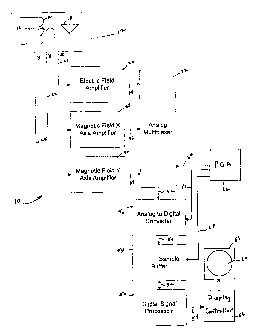
[0014] Figure 1 is a block diagram schematic of a CAT detection system 10
suitable for
embodying the broad principles of the present invention. Referring to Figure
l, a cross-
looped and sense antenna 12, which may be of the type used in the Stormscope~
avionics,
model WX-1000, for example, is mounted on-board an aircraft for use, during
flight, .in
monitoring the airspace ahead and surrounding the aircraft for electromagnetic
radiation.
More specifically, the antenna 12 comprises two antenna loops 14 and 16
arranged
perpendicular to one another with one aligned to receive magnetic radiation
along the
heading of the aircraft, referred to herein as the X magnetic field component,
and the other to
receive magnetic radiation transverse to the aircraft heading, referred to
herein as the Y
magnetic field component, for example. The antenna 12 further includes an
electric field
4
CA 02521960 2005-10-07
WO 2004/095078 PCT/US2004/001691
sense element 18 for receiving the electric field component of the
electromagnetic radiation,
referred to herein as the E field component.
[0015] The antenna 12 converts the received radiation components E, X, and Y
into
representative electrical analog signals which are output over respectively
corresponding
signal lines 20, 22, and 24 to amplifiers 26, 28 and 30, respectively. Each
amplifier 26, 28
and 30 may be a programmable gain amplifier to amplify its respective analog
signal by a
programmed gain in order to keep the amplified signal level within an
acceptable range for
analysis. In the present embodiment, each amplifier has gain settings of 1, 2,
5 and 10, but it
is understood by all those skilled in the pertinent art that other gain
settings are possible. The
gain setting for each amplifier may be either determined by experimentation
and preset
manually into the amplifier for operation, or determined from a monitoring of
the analysis
process during operation; in which case, the gain of an amplifier would be
automatically
adjusted to maintain the amplified level within an acceptable range for
analysis.
[0016] The amplified E, X and Y signals are coupled to inputs of an analog
multiplexer
circuit 32 over respective signal lines 34, 36 and 38. The multiplexer 32 may
be a
conventional four channel multiplexer with one unused chamlel, for example. A
selected
input signal of the multiplexer 32 is coupled over signal line 42 to an analog-
to-digital
converter circuit 40, which may be of the type manufactured by Analog Devices
under the
model no. AD625, for example. The converter 40 is operative to digitize the
signal over line
42 into a 16 bit word representative thereof, for example. Each digitized word
of the
converter 40 is supplied to a mass storage memory device 44, which may include
one or more
sample buffers, over signal lines 46. The memory 44 may be a conventional hard
disk drive
or a high density random access memory, for example, with the capacity to
store a
predetermined number of digitized samples of each of the signals E, X and Y.
The sample
data memory 44 may store the digitized samples of E, X and Y into respective
addressable
storage channels for convenient retrieval thereof for processing in a digital
signal processor
50, which may be of the type manufactured by Texas Instruments under the model
number
TMS 320CV31, for example. The processor 50 may address each sample buffer of
memory
44 to access the stored data samples over address, control and data lines 52.
[0017] In the present embodiment, two sample buffers are included in memory
44. One
may be used to store data samples as they are being digitized while the other
is accessed by
the processor for retrieval of stored data samples for the processing thereof
and vice versa.
CA 02521960 2005-10-07
WO 2004/095078 PCT/US2004/001691
Thus, the use of dual sample buffers in memory 44 permits continuous storage
and
processing of data samples by alternating between the two sample buffers. In
addition, the
multiplexes 32 and analog-to-digital converter 40 may be integrated on a
single "off the-
shel~' printed circuit card which may be of the type manufactured by
Measurement
Computing under the model or part no. PCI-DAS4020/12, for example.
[0018] As will become better understood from the more detailed description
below, the
digital signal processor 50 is programmed to analyze the data samples of the
three signal
components E, X and Y to detect CAT activity and determine the severity and
position
thereof, preferably in range and bearing in relation to the aircraft. In the
present embodiment,
when CAT radiation pulses are detected, their corresponding range and bearing
signals are
provided over signal lines 54 to a display controller 56 which drives a
display monitor 58 to
display the CAT activity and its position in relation to the aircraft on a
display screen 60
thereof, which is viewable by the pilot. The display controller 56 and display
monitor 58 may
be of the type used in the Stormscope avionics, model no. WX-1000, for
example. In the
alternative, information comprising the range and bearing to the CAT along
with an
indication of the severity thereof may be communicated across an avionics
network to a
weather radar display or a glass panel multi-functional avionics display, for
example, and
overlaid or superimposed onto an existing display image.
[0019] In addition, a programmed microcontroller or programmable gate array
(PGA) 62
may be programmed with the logic to coordinate in a time sequenced manner the
operations
of the multiplexes 32 over signal lines 64, the analog-to-digital converter 40
over signal lines
66 and the dual sample buffer memory 44 over signal lines 68, for example. The
PGA 62
may be of the field programmable type manufactured by Xilinx Inc. under model
number
XC95144XL, for example. In operation, the PGA 62 may control the multiplexes
32 via
signal lines 64 to pass each of its input signals E, X and Y sequentially to
the output line 42
periodically with a time period of approximately one microsecond, for example.
Thus, each
analog signal E, X, and Y is sampled by the multiplexes 32 at one microsecond
intervals or at
a sampling rate of one megahertz. Each signal over line 42 is given time to
stabilize by the
PGA 62, and then, the converter 40 is controlled via lines 66 to digitize the
selected analog
sample into a digital word which is presented over signal lines 46. Again, the
PGA 62 allows
for time for the digital word to stabilize on lines 46, then controls via
lines 68 the storage
thereof into the respective channel assigned to the selected sample.
6
CA 02521960 2005-10-07
WO 2004/095078 PCT/US2004/001691
[0020] In the present embodiment, each sample buffer of memory 44 is
configured to
store digital data sample words of each signal E, X and Y over a period of 20
milliseconds, or
20,000 data samples each. As one sample buffer fills with data samples, the
other sample
buffer previously filled over the preceding 20 milliseconds is accessed by the
processor 50
for processing the data samples thereof. The PGA 62 may control the storage of
data samples
into one of the sample buffers and determine when that buffer is filled, then
switch to the
other sample buffer and control the storage of data samples therein. Once the
other sample
buffer is filled, the process is repeated. Also, as each buffer is filled with
data samples, the
collection of data samples which may be 20,000 data samples for each signal E,
X and Y are
time tagged utilizing a real time clock which may be programmed into the PGA
62, for
example.
[0021] Figures 2A ad 2B depict an exemplary flowchart for use in programming
the
digital signal processor 50 to process the data samples stored in the sample
buffers of
memory 44. Referring to Figures 2A and 2B, the program starts execution at
block 70 which
instructs the processor 50 to access the data samples and corresponding time
tag of the filled
sample buffer of memory 44 in a sequential data stream starting with the first
data sample and
ending with the 20, 000th data sample. In block 72, a convolution algorithm
which includes
the characteristics of known CAT waveform signatures embedded therein is
called to process
the accessed data sample stream to identify a pulse or pulses of the data
stream which match
a CAT waveform signature to a predetermined degree. In the present embodiment,
the
convolution algorithm attaches a numerical value to each pulse of a data steam
processed
thereby. The numerical value is representative of a percentage of a match of a
pulse in the
data sample stream to a CAT waveform signature. For example, if the match is
perfect, the
algorithm may attach the number 1.0 (100% match); if the pulse is somewhat
matching, the
algorithm may attach the number 0.5 (50% match) to the pulse; and if there is
no match; the
algorithm may attach a 0 to the pulse. Those pulses of the data sample stream
which have a
match above a certain numerical value are identified as candidate pulses of
CAT activity and
time tagged.
[0022] In the present embodiment, the samples of the data stream of the E
signal may be
accessed first and processed sequentially by the convolution algorithm for
each E signal CAT
waveform signature. This may result in repeated convolutions for each possible
waveform
signature. Each pulse of the E signal data stream that meets the match
criteria as described
herein above is time tagged and stored. The width, polarity and amplitude of
each identified
7
CA 02521960 2005-10-07
WO 2004/095078 PCT/US2004/001691
pulse is determined and stored along with the time tag thereof. Then, the
samples of the data
stream of the X signal are accessed and processed by the convolution algorithm
in the same
manner as the E signal data stream. Those X signal pulses that meet the match
criteria are
identified and time tagged along with the width and amplitude thereof.
Finally, the samples of
the data stream of the Y signal are accessed and processed by the convolution
algorithm in
the same manner and the identified pulses are time tagged along with the width
and
amplitudes thereof. It is understood that the order in which the E, X and Y
data streams are
processed by the convolution algorithm may be changed to that described above
without
deviating from the broad principles of the present invention.
[0023] Once the data streams of the signals E, X and Y have been processed and
pulses
identified and time tagged, then the identified pulses are correlated based on
the time tags
thereof to ensure a pulse match of all three signals. That is, if one of the
signals E, X and Y
does not have a pulse match at a time substantially close to or within a
predetermined time
window of a pulse match of the other signals, then the identified pulse may
not be considered
coming from CAT activity. Each pulse that meets the match criteria and time
criteria across
all of the signals E, X and Y is flagged as a candidate pulse of CAT activity.
In the next block
74, the pulse width and amplitude of each candidate pulse identified from
block 72 are
compared with predetermined criteria to confirm that such pulses are CAT
pulses. Thereafter,
in decisional block 76, it is determined if there are any confirmed CAT pulses
resulting from
block 74. If so, then the bearing of each confirmed pulse is determined in
relation to the
heading of the aircraft in block 78 as a function of the amplitudes of the X
and Y component
pulses thereof. For example, the arctangent of the ratio of the Y pulse
amplitude to the X
pulse amplitude results in a bearing angle in relation to the heading of the
aircraft. Any
ambiguity in bearing may be resolved by the polarity of the associated E
component pulse or
by a relationship of the polarities of the correlated X, Y and E pulses of the
CAT activity.
Each CAT bearing measurement is stored in a memory location correlated to the
time tag of
its corresponding X, Y and E pulses.
[0024] Next, in block 80, a select number of data samples of the E signal
component and
either the X or Y signal component are taken about each confirmed pulse using
the time tag
thereof as a reference. It is known that CAT pulses may range from 100 to 400
microseconds
in width and that each data sample represents a time interval of one
microsecond. So, to
ensure that the whole pulse is included, the selected number of samples may
comprise around
one thousand samples, for example. In block 82, a Fast Fourier Transformation
(FFT) may be
8
CA 02521960 2005-10-07
WO 2004/095078 PCT/US2004/001691
performed on the selected number of time data samples about each confirmed
pulse. The FFT
results in 1000 frequency bins for each of the E signal component and the X or
Y signal
component. From an energy standpoint, 500 of the frequency bins are redundant
for each
component. Moreover, only frequencies on the order of 100 KHz, ~ 50 KHz (40-50
frequency bins) are characteristic of a CAT pulse and therefore, of concern
for the
determination of range for each confirmed pulse.
[0025] In block ~4, the composite energy of these 40-50 frequency bins is
determined for
use in calculating range from the aircraft to the confirmed CAT pulse. Range
is determined
based on the presumption that the further the CAT activity is from the
aircraft, the further the
radiation produced thereby has to travel, thus the weaker the energy of the
signal. From this
presumption, range for each conftrmed pulse may be deternzined as an inverse
function of the
composite energy calculated therefor. Also, if the calculated energy for a
confirmed pulse is
below a predetermined level, the associated pulse may be ignored. Once the
range is
determined for each confirmed pulse, it is time tagged in block ~6 based on
the corresponding
pulse and stored accordingly. Then, in block ~~, the range and bearing
measurements of each
confirmed pulse are correlated based on the time tags thereof. These range and
bearing
measurements locate the position of the associated CAT activity in relation to
the aircraft.
[0026] In the range calculation, it is possible that less severe close in CAT
may present
itself as distant CAT and vice versa when calculating range from the composite
energy of one
or more isolated pulses. Using the composite energies from both the E and X or
Y pulses
provides a form of discrimination for any ambiguities in range calculation
from the
composite energy of an isolated pulse. In addition, since CAT comprises
multiple radiation
discharges or pulses, as the aircraft approaches the CAT, a gradual increase
in composite
energy from known bands or bins of frequencies of the CAT pulses may be
detected as
described herein above. Thus, observing the trend in the composite energy from
the E
component and X or Y component pulses as the aircraft approaches the CAT helps
to resolve
any position ambiguity which may result from the composite energy of isolated
groups of
pulses.
[0027] Thereafter, in block 90, each range and bearing pair of measurements
are supplied
to the display controller 50 so that symbols corresponding to the associated
CAT activity may
be displayed on the screen 60 of the monitor 5~ at locations in range and
bearing in relation
to the aircraft or communicated across the avionics network as noted above. An
aircraft
9
CA 02521960 2005-10-07
WO 2004/095078 PCT/US2004/001691
symbol may appear on the screen 60 so that the pilot may view a map of the CAT
activity in
relation to the aircraft. The program execution may then return to block 70 to
repeat the
processing for the data samples of the other sample buffer of memory 44.
Program execution
will also be deviated back to block 70 if no turbulence is detected by the
decisional block 76.
It is understood that, by design, the processing of the data samples of one of
the sample
buffers will occur in the digital signal processor at a faster rate than the
rate of filling the
other sample buffer with data samples. Thus, a wait loop may be designed in
the program of
the digital signal processor 50 to permit it to wait until the other sample
buffer is filled before
accessing data samples therefrom. In any event, the processor 50 may process
the data
samples of one sample buffer and then the other alternately in accordance with
the foregoing
described processing steps.
[0028] It is understood that the embodiment presented above merely describes
the
invention by way of example and that additions, deletions and modifications
may be made
thereto without deviating with the broad principles of the present invention.
Accordingly, the
present invention should not be limited to any single embodiment, but rather
construed in
breadth and broad scope in accordance with the recitation of the appended
claims.